

EAW DX1208 Instruction Manual

INSTRUCTION MANUAL
8
S/PDIF
9/10
11/12
7 6 5
LOGIC
3OUT
GND GND
GND
2OUT 1OUT 6IN 5IN 4IN 3IN 2IN 1IN ININININ
ININININ
4 3 2 1
8 7 6 5
GNDGNDGNDGNDGNDGNDGNDGND
DX 1208
GND
GND
GND
GND
GND
GND
ININININ
RLRLR
L
IN
IN
ADDRESS
ETHERNET
RS232
ANALOG
OUTPUT
GNDGNDGNDGNDGNDGNDGNDGND
D C B AH G F E
DX LINK RX
DX LINK TX
REMOTES
ON
COMM
DX LINK ACTIVE
DX 1208
MATRIX MIXER
1 2 3 4 5 6 7 8
INPUT
A B C D E H
CLIP
-40
9/10 11/12
OUTPUT
CLIP
-40
ON
F G
DX1208
12x8 Digital Matrix Mixer and Signal Processor
1. IMPORTANT SAFETY INSTRUCTIONS
CAUTION AVIS
RISK OF ELECTRIC SHOCK • DO NOT OPEN
RISQUE DE CHOC ELECTRIQUE
NE PAS OUVRIR
CAUTION: TO REDUCE THE RISK OF ELECTRIC SHOCK
DO NOT REMOVE COVER (OR BACK)
NO USER-SERVICEABLE PARTS INSIDE
REFER SERVICING TO QUALIFIED PERSONNEL
ATTENTION: POUR EVITER LES RISQUES DE CHOC
ELECTRIQUE, NE PAS ENLEVER LE COUVERCLE. AUCUN
ENTRETIEN DE PIECES INTERIEURES PAR L'USAGER. CONFIER
L'ENTRETIEN AU PERSONNEL QUALIFIE.
AVIS: POUR EVITER LES RISQUES D'INCENDIE OU
D'ELECTROCUTION, N'EXPOSEZ PAS CET ARTICLE
A LA PLUIE OU A L'HUMIDITE
The lightning flash with arrowhead symbol within an equilateral triangle is
intended to alert the user to the presence of uninsulated "dangerous voltage"
within the product's enclosure, that may be of sufficient magnitude to constitute
a risk of electric shock to persons.
Le symbole éclair avec point de èche à l'intérieur d'un triangle équilatéral est
utilisé pour alerter l'utilisateur de la présence à l'intérieur du coret de "voltage
dangereux" non isolé d'ampleur susante pour constituer un risque d'éléctrocution.
The exclamation point within an equilateral triangle is intended to alert the user
of the presence of important operating and maintenance (servicing) instructions
in the literature accompanying the appliance.
Le point d'exclamation à l'intérieur d'un triangle équilatéral est employé pour
alerter les utilisateurs de la présence d'instructions importantes pour le fonctionnement et l'entretien (service) dans le livret d'instruction accompagnant l'appareil.
PORTABLE CART
WARNING
1. Read these instructions.
2. Keep these instructions.
3. Heed all warnings.
4. Follow all instructions.
5. Do not use this apparatus near water.
6. Clean only with dry cloth.
7. Do not block any ventilation openings. Install in accordance with the
manufacturer's instructions.
8. Do not install near any heat sources such as radiators, heat registers,
stoves, or other apparatus (including amplifiers) that produce heat.
9.
Do not defeat the safety purpose of the polarized or grounding-type
plug. A
polarized plug has two blades with one wider than the other. A
grounding type plug has two blades and a third grounding prong. The wide
blade or the third prong are provided for your safety. If the provided plug
does not fit into your outlet, consult an electrician for replacement of the
obsolete outlet.
10. Protect the power cord from being walked on or pinched particularly at
plugs, convenience receptacles, and the point where they exit from the
apparatus.
11. Only use attachments/accessories specified by the manufacturer.
12. Use only with the cart, stand, tripod, bracket,
or table specified by the manufacturer, or
sold with the apparatus. When a cart is used,
use caution when moving the cart/apparatus
combination to avoid injury from tip-over.
13. Unplug this apparatus during lightning storms
or when unused for long periods of time.
14. Refer all servicing to qualified service
personnel. Servicing is required when the
apparatus has been damaged in any way, such as power-supply cord or
plug is damaged, liquid has been spilled or objects have fallen into the
apparatus, the apparatus has been exposed to rain or moisture, does not
operate normally, or has been dropped.
15. Do not overload wall outlets and extension cords as this can result in a risk
of fire or electric shock.
16. This apparatus has been designed with Class-I construction and must be
connected to a mains socket outlet with a protective earthing connection
(the third grounding prong).
17. This apparatus has been equipped with a rocker-style AC mains power
switch. This switch is located on the rear panel and should remain readily
accessible to the user.
18. The mains plug or an appliance coupler is used as the disconnect device,
so the disconnect device shall remain readily operable.
19. NOTE: This equipment has been tested and found to comply with the limits
for a Class A, digital device, pursuant to Part 15 of the FCC Rules, and
the rules for Canada under ICES-003 - Feb 04. These limits are designed
to provide reasonable protection against harmful interference when the
equipment is operated in a commercial environment. This equipment
generates, uses, and can radiate radio frequency energy and, if not
installed and used in accordance with the instruction manual, may cause
harmful interference to radio communications. Operation of this equipment
in a residential area is likely to cause harmful interference in which
case the user will be required to correct the interference at his/her own
expense.
CAUTION: Changes or modifications to this device not expressly approved
by LOUD Technologies Inc. could void the user’s authority to operate the
equipment under FCC rules.
WARNING! This equipment has been designed to be installed
by qualified professionals only! There are many factors to be
considered when installing professional sound reinforcement
systems, including mechanical and electrical considerations, as well
as acoustic coverage and performance. EAW Commercial strongly
recommends that this equipment be installed only by a professional
sound installer or contractor.
2 – DX1208
Correct disposal of this product. This symbol indicates that this product should not be disposed of with your household waste, according to the WEEE Directive (2002/96/EC) and your national law. This product
should be handed over to an authorized collection site for recycling waste electrical and electronic equipment (EEE). Improper handling of this type of waste could have a possible negative impact on the environment
and human health due to potentially hazardous substances that are generally associated with EEE. At the same time, your cooperation in the correct disposal of this product will contribute to the effective usage of
natural resources. For more information about where you can drop off your waste equipment for recycling, please contact your local city office, waste authority, or your household waste disposal service.
WARNING — To reduce the risk of fire or
electric shock, do not expose this appliance to
rain or moisture.
CAUTION — Internal lithium battery. Danger
of explosion if battery is incorrectly replaced.
Replace only with the same or equivalent type.

Table of Contents
1. IMPORTANT SAFETY INSTRUCTIONS ........................................ 2
2. INTRODUCTION............................................................................... 4
Key Features.................................................................................. 4
Unpacking...................................................................................... 4
Front Panel Features ..................................................................... 5
Rear Panel Features ...................................................................... 5
3. HARDWARE INSTALLATION ......................................................... 6
Connections................................................................................... 6
AC Power Considerations ........................................................... 10
4. SOFTWARE INSTALLATION ........................................................ 10
Computer Requirements ............................................................. 10
Installing the Drivers and DX Navigator ..................................... 10
Establishing Communication Over USB ...................................... 14
Communicating Over Ethernet .................................................... 14
Communicating Over RS232 ....................................................... 15
Upgrading the Firmware ............................................................. 15
5. TYPICAL HOOKUP DIAGRAM ..................................................... 15
6. SPECIFICATIONS........................................................................... 16
DX1208 Specifications ................................................................ 16
Disclaimer ................................................................................... 17
Block Diagram ............................................................................. 18
7. SERVICE INFORMATION .............................................................. 19
Part No. 0028766-00 Rev. B 06/09
© 2009 LOUD Technologies Inc. All Rights Reserved.
DX1208 – 3
2. INTRODUCTION
KEY FEATURES
The DX1208 is a 12-input, 8-output DSP matrix mixer
designed for use in a variety of commercial and installed
sound applications such as churches, courtrooms, convention
centers, and hotels. Eight inputs are mic/line capable, with
selectable 48-volt phantom power provided for each input.
These 8 inputs and the 8 outputs are accessed using Euroblock
detachable connectors. Four additional inputs on unbalanced
RCA connectors allow the user to “stack” inputs (inputs 5-8),
increasing the number of audio sources that can be connected.
An additional four digital inputs are available on S/PDIF
connectors with sample rate conversion to 48 kHz. All 12
inputs are included in the audio matrix and can be assigned
DSP functions prior to distributing signal at line level.
The DX1208 can also receive up to 6 logic inputs and
send up to 3 logic outputs, programmable via the included DX
Navigator control software. Control of the DX1208 via third
party systems (i.e., AMX and Crestron) is easily attained with
an RS-232C serial connection (DB9) on the rear panel. Two
RJ-45 connections are provided as well for linking multiple (up
to eight) DX Link enabled products together in a ring network
topology.
A remote control port (RJ-25 connector) is included on the
rear panel, facilitating the connection of two different types of
remotes (UR-1 and UR-2), all mounted on wall panels. Up to 10
remotes can be attached to the DX1208 (more when external
power is supplied), and each is individually addressable and
configurable.
The DX1208 is supplied with DX Navigator control
software that allows access to all of the system’s settings and
configurations using a personal computer (PC). The expected
rangeofuser-adjustableprocessing,suchasEQlters,gates,
compressors,limiters,AGC,duckingandpriorityassignment,
delay, gain, and crossovers are included. The Automix feature
employs a gain sharing automixer, to keep the overall system
gain constant. In addition, up to 24 programmable presets are
available per DX1208, which can be used to store and recall
frequently used settings. The programming interface is flexible,
with connection via the USB port on the front panel, or the
Ethernet jack or DB9 connector on the rear panel.
The DX1208 is UL and CE approved. It is designed for
continuous use in professional fixed installation systems and
employsauniversalpowersupply(100-240VAC,50/60Hz).
• 32-bitDSPand24-bitAnalog/DigitalConversion
• 8balancedMic/LineinputsonEuroblockconnectors
• Individuallyselectable48VphantompoweronMic/Line
inputs 1-8
• 4additionalunbalancedlineinputsstackedtoinputs5-8on
RCA connectors
• Inputs9/10and11/12onS/PDIFconnectorsfordigital
inputs
• Gate,compressor/AGC,andsixbandEQoneachinput
• Muteandsolobuttononeachinput
• 8balancedline-leveloutputsonEuroblockconnectors
• Limiter,eightbandEQplustwocrossoverlters,anddelay
on each output
• 6logicinputsand3logicoutputs
• DXLinkenablessmallinstallationnetworks,providingan
additional 16 inputs (IDX) and 16 outputs (ODX)
• Automixfeaturemaximizesacousticgainwithoutfeedback
• Adjustableduckingwith5prioritylevelsassignabletoeach
input (inputs 1-12 and IDX inputs 1-16)
• 1remotecontrolportforconnectionandcontrolofupto10
remotes
• 1USBportonthefrontpanelforcontrolandprogramming
with a PC
• RearpanelDB9connectorforRS-232Ccommunications
with third party devices (AMX, Crestron)
• RearpanelEthernetconnectioncanalsobeusedforcontrol
and programming
• ComprehensivegraphicaluserinterfaceusingDXNavigator
software
UNPACKING
Contents
Qty Item
1 DetachableLineCord115VAC
1 DetachableLineCord230VAC
16 3-position Euroblock connectors for audio I/O
9 2-position Euroblock connectors for logic I/O
2 Rack Ears (installed on product)
1 CD-ROM containing DX Navigator installer
(Windows)
1 Instruction Manual (this document)
4 – DX1208
COMM
DX LINK ACTIVE
DX 1208
MATRIX MIXER
1 2 3 4 5 6 7 8
INPUT
A B C D E H
CLIP
-4 0
9/10 11/ 12
OUTPUT
CLIP
-4 0
ON
F G
FRONT PANEL FEATURES
8
S/PDI F
9/1 0
11/ 12
7 6 5
LOGIC
3OUT
GND GND
GND
2OUT 1OUT 6I N 5IN 4I N 3IN 2IN 1IN INI NININ
ININININ
4 3 2 1
8 7 6 5
GNDGNDGNDGNDGNDGNDGNDGND
DX 1208
GND
GND
GND
GND
GND
GND
ININI NI N
RLRLR
L
IN
IN
ADDRESS
ETHERNET
RS232
ANALOG
OUTPUT
GNDGNDGNDGNDGNDGNDGNDGND
D C B AH G F E
DX LINK RX
DX LINK TX
REMOTES
ON
COMM
DX LINK ACTIVE
DX 1208
MATRIX MIXER
1 2 3 4 5 6 7 8
INPUT
A B C D E H
CLIP
-4 0
9/10 11/ 12
OUTPUT
CLIP
-4 0
ON
F G
REAR PANEL FEATURES
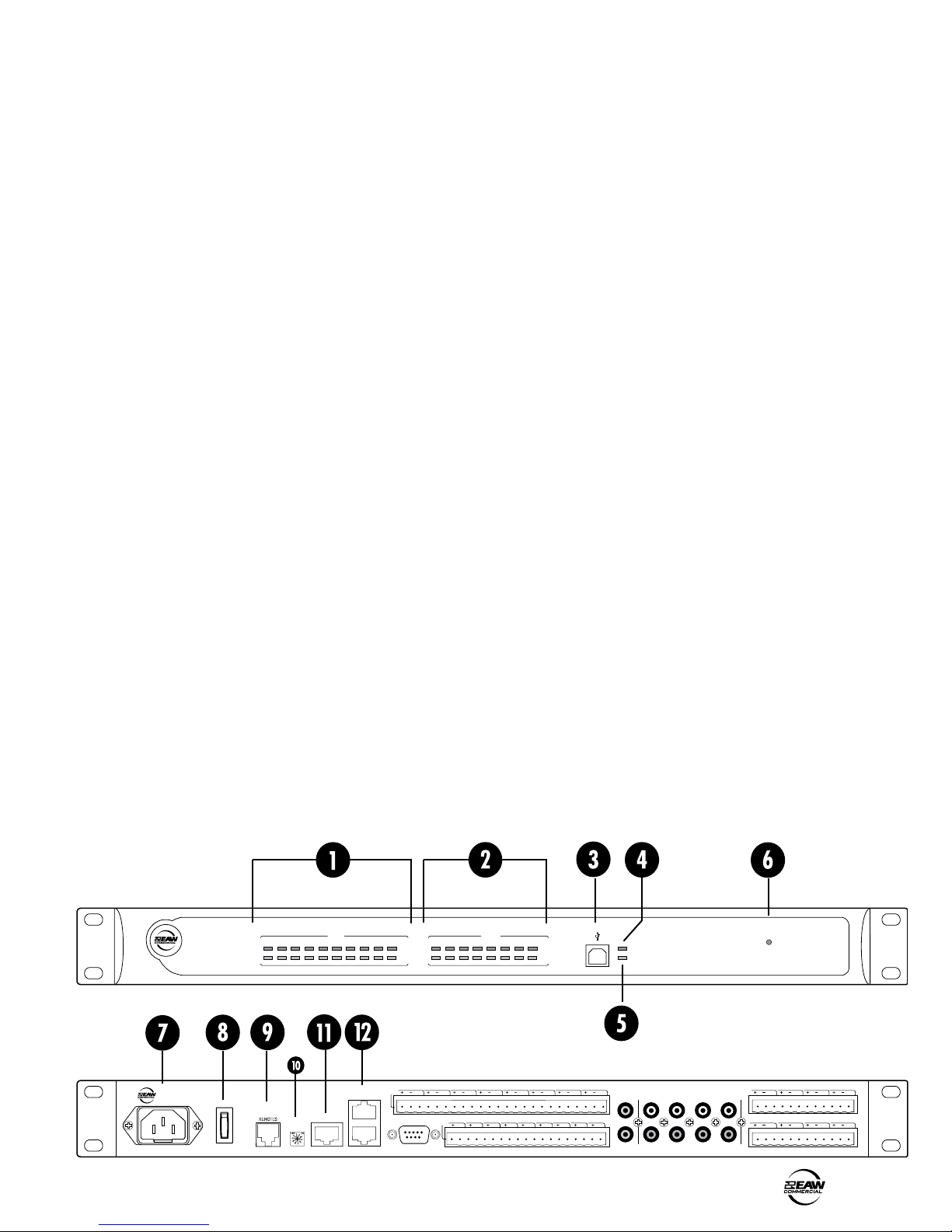
The front panel consists mostly of indicators showing the
status of the DX1208, with the exception of the USB connector
for easy programming access with a PC.
1. INPUT LEVEL INDICATORS
Each input channel has a pair of level indicators. The green
LED indicates the presence of a signal above –40 dBFS.
The red LED indicates when the signal is above –2 dBFS
and is close to clipping.
2. OUTPUT LEVEL INDICATORS
Each output channel has a pair of level indicators. The green
LED indicates the presence of a signal above –40 dBFS.
The red LED indicates when the signal is above –2 dBFS
and is close to clipping.
3. USB CONNECTOR
Use this standard USB connector to connect the DX1208 to
a PC with DX Navigator installed.
4. DX LINK ACTIVE
This red LED lights continuously to indicate when a DX Link
enabled device is connected to the DX LINK RX connector
on the rear panel and is communicating correctly.
7. IEC AC SOCKET
The DX1208 has a universal power supply, allowing it to
operatefromanyACmainssupplyfrom100to240VAC,
50-60 Hz. The DX1208 comes with two IEC power cables,
onefor120Voperationandonefor220Voperation.Select
the power cable appropriate for your local AC power and
connect it to the IEC AC socket.
8. ON SWITCH
Use the ON switch to turn the DX1208 on and off.
9. REMOTES
This RJ-25 connector is used to connect to one or more
optional remote controls. Up to 10 UR-family remotes may
be connected in a daisy-chain to this remote control port
(more when external power is supplied). See “Connecting
the REMOTES” on page 9 for more information on using the
remote controls.
10.
ADDRESS
Currently disabled, this multi-position rotary switch will be
implemented in future software updates.
11.
ETHERNET
5. COMM
This green LED lights to indicate communication activity
via the USB, RS-232, Ethernet, Remotes, or Logic Input
connections.
6. ON
This green LED lights when the power switch is turned
on and the DX1208 is connected to an AC mains with
sufficient voltage for operation.
This RJ-45 connector allows the DX1208 to be controlled
and programmed by a PC with a 10/100 Base-T Ethernet
connection.
12.
DX LINK RX/TX
These RJ-45 connectors are used to connect multiple DX
Link enabled devices together. The DX LINK RX connector
receives audio from devices that are located upstream in
the audio path, and the DX LINK TX connector transmits
audio to devices that are located downstream in the audio
path. See “Connecting the DX LINK RX/TX” on page 9 for
more information on using the DX Link connections.
DX1208 – 5
13.
8
S/PDI F
9/1 0
11/ 12
7 6 5
LOGIC
3OUT
GND GND
GND
2OUT 1OUT 6I N 5IN 4I N 3IN 2IN 1IN INI NININ
ININININ
4 3 2 1
8 7 6 5
GNDGNDGNDGNDGNDGNDGNDGND
DX 1208
GND
GND
GND
GND
GND
GND
ININI NI N
RLRLR
L
IN
IN
ADDRESS
ETHERNET
RS232
ANALOG
OUTPUT
GNDGNDGNDGNDGNDGNDGNDGND
D C B AH G F E
DX LINK RX
DX LINK TX
REMOTES
ON
COMM
DX LINK ACTIVE
DX 1208
MATRIX MIXER
1 2 3 4 5 6 7 8
INPUT
A B C D E H
CLIP
-4 0
9/10 11/ 12
OUTPUT
CLIP
-4 0
ON
F G
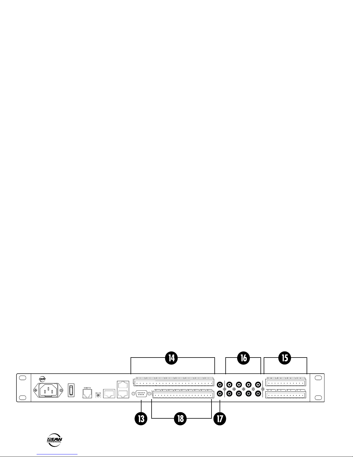
RS232
18.
LOGIC I/O
This is an RS-232C port on a 9-pin (DB9) connector. It
connects to a personal computer or other compatible
control system for external control of the DX1208 settings.
This may be used instead of the USB port or the Ethernet
connection for programming the DX1208.
14.
ANALOG OUTPUTS A-H
Eight balanced line-level outputs are provided on these
Euroblock connectors, labeled A-H.
15.
ANALOG INPUTS 1-8
Connect eight balanced mic or line-level inputs to these
Euroblock connectors. The input gain is adjusted in the DX
Navigator software application to accommodate a mic or
line-levelsignal.48Vphantompowercanalsobeapplied
to a microphone input by activating it in the DX Navigator
DX1208 user-interface.
16.
ANALOG INPUTS 5-8
These RCA connectors accept unbalanced line-level
inputs(–10dBV)toaccommodateconsumersourcessuch
as CD or MP3 players. The left and right inputs for each
channel are summed to mono internally. It is possible to
have a signal connected to both balanced (Euroblock) and
unbalanced (RCA) connectors for inputs 5-8. The signals are
summed together in the analog domain, just prior to A/D
conversion.
17.
S/PDIF IN 9/10 and 11/12
These RCA connectors are used to connect S/PDIF digital
inputs to the DX1208. The sample rate is automatically
detected and converted to 48 kHz for internal processing.
The DX1208 provides six logic inputs and three logic
outputs on Euroblock connectors. The inputs can be used
to control a variety of DX1208 functions via external
switching, such as preset recall or channel muting. The
outputs can be used to provide logic for external indicators
and switches to indicate a range of internal settings and
conditions.
Each logic input and output is comprised of two pins, the
active pin and ground. See “Connecting the Logic I/O”
on page 8 for suggested logic input and output wiring
examples.
3. HARDWARE INSTALLATION
The DX1208 ships with rack ears installed, which allows
the unit to be mounted in a standard 19" rack, requiring one
rack unit (1.75"). When mounting in a rack, use plastic washers
to protect the rack ears from the mounting screws.
Note: Since the DX1208 is convection cooled with
ventilation slots on the sides and top, please allow one rack
space above the DX1208 to allow proper ventilation.
If you do not rack mount the DX1208, you may remove the
rack ears if desired.
CONNECTIONS
Connecting Balanced Sources
Use high-quality three-conductor cable for balanced input
connections. The better the shield, the better the audio signal
is protected from induced EMI and RFI.
Note: With screw-down Euroblock connectors, it’s best
to use stranded wire that is not tinned. Solder can “flow”
under the pressure of the screw-down terminal and cause the
connection to become loose.
6 – DX1208
 Loading...