

Page 1
DSA250 & DSA230 LOUDSPEAKER
OWNER’S MANUAL
Page 2

DSA Owner’s Manual
TABLE OF CONTENTS
Introduction
Chapter 1 Safety
1.1 Safety Precautions . . . . . . . . . . . . . . . . . . . . . . . . . . . . . . . . . . . . . . . . . . . . . . . . . . . . . . . . . . 5
1.2 Safety Instructions . . . . . . . . . . . . . . . . . . . . . . . . . . . . . . . . . . . . . . . . . . . . . . . . . . . . . . . . . . 5
1.2.1 General Precautions . . . . . . . . . . . . . . . . . . . . . . . . . . . . . . . . . . . . . . . . . . . . . . . . . . . . . . . . 6
Chapter 2 Unpacking
2.1 Contents. . . . . . . . . . . . . . . . . . . . . . . . . . . . . . . . . . . . . . . . . . . . . . . . . . . . . . . . . . . . . . . . . . . 7
2.2 Shipping Damage . . . . . . . . . . . . . . . . . . . . . . . . . . . . . . . . . . . . . . . . . . . . . . . . . . . . . . . . . . 7
2.3 Returning Products to EAW. . . . . . . . . . . . . . . . . . . . . . . . . . . . . . . . . . . . . . . . . . . . . . . . . . 7
Chapter 3 Quick Start
3.1 Description . . . . . . . . . . . . . . . . . . . . . . . . . . . . . . . . . . . . . . . . . . . . . . . . . . . . . . . . . . . . . . . . 8
3.2 Audio Signal Connection. . . . . . . . . . . . . . . . . . . . . . . . . . . . . . . . . . . . . . . . . . . . . . . . . . . . 8
3.3 Computer Control Connection. . . . . . . . . . . . . . . . . . . . . . . . . . . . . . . . . . . . . . . . . . . . . . . 8
3.4 Daisy Chaining Audio and Computer Signal Between Loudspeakers. . . . . . . . . . . . 8
3.5 AC Mains Installation. . . . . . . . . . . . . . . . . . . . . . . . . . . . . . . . . . . . . . . . . . . . . . . . . . . . . . . . 9
3.5.1 AC Mains Supply . . . . . . . . . . . . . . . . . . . . . . . . . . . . . . . . . . . . . . . . . . . . . . . . . . . . . . . . . . . 9
3.5.2 AC Mains Cable. . . . . . . . . . . . . . . . . . . . . . . . . . . . . . . . . . . . . . . . . . . . . . . . . . . . . . . . . . . . . 9
3.6 Physical Installation. . . . . . . . . . . . . . . . . . . . . . . . . . . . . . . . . . . . . . . . . . . . . . . . . . . . . . . . . 9
3.6.1 Orientation . . . . . . . . . . . . . . . . . . . . . . . . . . . . . . . . . . . . . . . . . . . . . . . . . . . . . . . . . . . . . . . . 9
3.6.2 Mounting . . . . . . . . . . . . . . . . . . . . . . . . . . . . . . . . . . . . . . . . . . . . . . . . . . . . . . . . . . . . . . . . . . 9
3.7 Signal Processing. . . . . . . . . . . . . . . . . . . . . . . . . . . . . . . . . . . . . . . . . . . . . . . . . . . . . . . . . . . 10
Chapter 4 Description
4.1 System Overview . . . . . . . . . . . . . . . . . . . . . . . . . . . . . . . . . . . . . . . . . . . . . . . . . . . . . . . . . . . 11
4.1.1 DSA Series Models. . . . . . . . . . . . . . . . . . . . . . . . . . . . . . . . . . . . . . . . . . . . . . . . . . . . . . . . . . 11
4.1.2 Acoustical Benefits. . . . . . . . . . . . . . . . . . . . . . . . . . . . . . . . . . . . . . . . . . . . . . . . . . . . . . . . . . 11
4.1.3 Physical Benefits. . . . . . . . . . . . . . . . . . . . . . . . . . . . . . . . . . . . . . . . . . . . . . . . . . . . . . . . . . . . 11
4.1.4 Electrical Benefits. . . . . . . . . . . . . . . . . . . . . . . . . . . . . . . . . . . . . . . . . . . . . . . . . . . . . . . . . . . 12
4.2 Features . . . . . . . . . . . . . . . . . . . . . . . . . . . . . . . . . . . . . . . . . . . . . . . . . . . . . . . . . . . . . . . . . . . 12
4.2.1 Acoustical. . . . . . . . . . . . . . . . . . . . . . . . . . . . . . . . . . . . . . . . . . . . . . . . . . . . . . . . . . . . . . . . . . 12
4.2.2 Electronic . . . . . . . . . . . . . . . . . . . . . . . . . . . . . . . . . . . . . . . . . . . . . . . . . . . . . . . . . . . . . . . . . . 12
4.2.3 Computer Control . . . . . . . . . . . . . . . . . . . . . . . . . . . . . . . . . . . . . . . . . . . . . . . . . . . . . . . . . . 12
4.2.4 Networking . . . . . . . . . . . . . . . . . . . . . . . . . . . . . . . . . . . . . . . . . . . . . . . . . . . . . . . . . . . . . . . . 12
4.2.5 Physical. . . . . . . . . . . . . . . . . . . . . . . . . . . . . . . . . . . . . . . . . . . . . . . . . . . . . . . . . . . . . . . . . . . . 13
4.3 Applications. . . . . . . . . . . . . . . . . . . . . . . . . . . . . . . . . . . . . . . . . . . . . . . . . . . . . . . . . . . . . . . . 13
4.4 Engineering Design. . . . . . . . . . . . . . . . . . . . . . . . . . . . . . . . . . . . . . . . . . . . . . . . . . . . . . . . . 14
4.5 DSAPilot . . . . . . . . . . . . . . . . . . . . . . . . . . . . . . . . . . . . . . . . . . . . . . . . . . . . . . . . . . . . . . . . . . . 15
4.6 Low Frequency Performance . . . . . . . . . . . . . . . . . . . . . . . . . . . . . . . . . . . . . . . . . . . . . . . . 15
4.7 Comparison To Traditional Products. . . . . . . . . . . . . . . . . . . . . . . . . . . . . . . . . . . . . . . . . . 15
4.8 Designing DSA Systems . . . . . . . . . . . . . . . . . . . . . . . . . . . . . . . . . . . . . . . . . . . . . . . . . . . . . 16
Chapter 5 Installation
5.1 Electrical Installation . . . . . . . . . . . . . . . . . . . . . . . . . . . . . . . . . . . . . . . . . . . . . . . . . . . . . . . . 16
5.1.1 Cable Routing Considerations . . . . . . . . . . . . . . . . . . . . . . . . . . . . . . . . . . . . . . . . . . . . . . . 16
5.1.2 Audio Signal Connection. . . . . . . . . . . . . . . . . . . . . . . . . . . . . . . . . . . . . . . . . . . . . . . . . . . . 17
5.1.3 Computer Control Connection. . . . . . . . . . . . . . . . . . . . . . . . . . . . . . . . . . . . . . . . . . . . . . . 17
5.1.4 Daisy Chaining Computer and Audio Signals Within Clusters with Multiple Loudspeakers. . . 1 7
5.1.5 Daisy Chaining Computer and Audio Signals Between Clusters. . . . . . . . . . . . . . . . . 18
5.1.6 EIA-485 Terminate Switch . . . . . . . . . . . . . . . . . . . . . . . . . . . . . . . . . . . . . . . . . . . . . . . . . . . 18
5.2 CobraNet™ Network Connections . . . . . . . . . . . . . . . . . . . . . . . . . . . . . . . . . . . . . . . . . . . 18
5.2.1 Description . . . . . . . . . . . . . . . . . . . . . . . . . . . . . . . . . . . . . . . . . . . . . . . . . . . . . . . . . . . . . . . . 18
5.2.2 CobraNet™ is Usually Desirable To Use When . . . . . . . . . . . . . . . . . . . . . . . . . . . . . . . . . 18
5.2.3 Additional Equipment You Must Supply For CobraNet™:. . . . . . . . . . . . . . . . . . . . . . . 19
5.2.4 Cabling . . . . . . . . . . . . . . . . . . . . . . . . . . . . . . . . . . . . . . . . . . . . . . . . . . . . . . . . . . . . . . . . . . . . 19
5.2.5 Audio/Computer Interface . . . . . . . . . . . . . . . . . . . . . . . . . . . . . . . . . . . . . . . . . . . . . . . . . . 19
5.2.6 Loudspeaker Interface . . . . . . . . . . . . . . . . . . . . . . . . . . . . . . . . . . . . . . . . . . . . . . . . . . . . . . 19
5.2.7 Multiple Loudspeakers . . . . . . . . . . . . . . . . . . . . . . . . . . . . . . . . . . . . . . . . . . . . . . . . . . . . . . 19
5.2.8 Support For CobraNet™/Ethernet. . . . . . . . . . . . . . . . . . . . . . . . . . . . . . . . . . . . . . . . . . . . 19
2
Page 3

5.3 AC Mains Power Connection. . . . . . . . . . . . . . . . . . . . . . . . . . . . . . . . . . . . . . . . . . . . . . . . . 20
5.3.1 AC Mains Supply . . . . . . . . . . . . . . . . . . . . . . . . . . . . . . . . . . . . . . . . . . . . . . . . . . . . . . . . . . . 20
5.3.2 AC Mains Cable. . . . . . . . . . . . . . . . . . . . . . . . . . . . . . . . . . . . . . . . . . . . . . . . . . . . . . . . . . . . . 20
5.3.3 Power On / Off . . . . . . . . . . . . . . . . . . . . . . . . . . . . . . . . . . . . . . . . . . . . . . . . . . . . . . . . . . . . . 20
5.3.4 AC Mains Fuse. . . . . . . . . . . . . . . . . . . . . . . . . . . . . . . . . . . . . . . . . . . . . . . . . . . . . . . . . . . . . . 21
5.4 Grounding . . . . . . . . . . . . . . . . . . . . . . . . . . . . . . . . . . . . . . . . . . . . . . . . . . . . . . . . . . . . . . . . . 21
5.4.1 Electrical Ground . . . . . . . . . . . . . . . . . . . . . . . . . . . . . . . . . . . . . . . . . . . . . . . . . . . . . . . . . . . 21
5.4.2 Audio Ground . . . . . . . . . . . . . . . . . . . . . . . . . . . . . . . . . . . . . . . . . . . . . . . . . . . . . . . . . . . . . . 21
5.5 Physical Installation. . . . . . . . . . . . . . . . . . . . . . . . . . . . . . . . . . . . . . . . . . . . . . . . . . . . . . . . . 22
5.5.1 Installation Warnings. . . . . . . . . . . . . . . . . . . . . . . . . . . . . . . . . . . . . . . . . . . . . . . . . . . . . . . . 22
5.5.2 Physical Orientation - Signal End / Power End. . . . . . . . . . . . . . . . . . . . . . . . . . . . . . . . . 22
5.5.3 Multiple Loudspeakers and Cluster Configurations . . . . . . . . . . . . . . . . . . . . . . . . . . . 23
5.5.4 Installation Options. . . . . . . . . . . . . . . . . . . . . . . . . . . . . . . . . . . . . . . . . . . . . . . . . . . . . . . . . 24
5.5.5 Angling Enclosures . . . . . . . . . . . . . . . . . . . . . . . . . . . . . . . . . . . . . . . . . . . . . . . . . . . . . . . . . 24
5.5.6 Mounting Height . . . . . . . . . . . . . . . . . . . . . . . . . . . . . . . . . . . . . . . . . . . . . . . . . . . . . . . . . . . 25
5.5.7 Wall Bracket Installation. . . . . . . . . . . . . . . . . . . . . . . . . . . . . . . . . . . . . . . . . . . . . . . . . . . . . 25
5.5.8 Enclosure Bracket Installation. . . . . . . . . . . . . . . . . . . . . . . . . . . . . . . . . . . . . . . . . . . . . . . . 27
5.5.9 Enclosure Installation . . . . . . . . . . . . . . . . . . . . . . . . . . . . . . . . . . . . . . . . . . . . . . . . . . . . . . . 27
5.6 Initial Set-Up . . . . . . . . . . . . . . . . . . . . . . . . . . . . . . . . . . . . . . . . . . . . . . . . . . . . . . . . . . . . . . . 29
5.6.1 Verify Loudspeaker Orientation and Position. . . . . . . . . . . . . . . . . . . . . . . . . . . . . . . . . . 29
5.7 Acoustical Installation. . . . . . . . . . . . . . . . . . . . . . . . . . . . . . . . . . . . . . . . . . . . . . . . . . . . . . . 29
Chapter 6 Operation
6.1 Operational Functions . . . . . . . . . . . . . . . . . . . . . . . . . . . . . . . . . . . . . . . . . . . . . . . . . . . . . . 30
6.1.1 Power Management . . . . . . . . . . . . . . . . . . . . . . . . . . . . . . . . . . . . . . . . . . . . . . . . . . . . . . . . 30
6.1.2 LED Indicator. . . . . . . . . . . . . . . . . . . . . . . . . . . . . . . . . . . . . . . . . . . . . . . . . . . . . . . . . . . . . . . 30
6.1.3 Signal Monitoring . . . . . . . . . . . . . . . . . . . . . . . . . . . . . . . . . . . . . . . . . . . . . . . . . . . . . . . . . . 31
6.2 Operational Check List . . . . . . . . . . . . . . . . . . . . . . . . . . . . . . . . . . . . . . . . . . . . . . . . . . . . . . 32
6.3 Normal Operation . . . . . . . . . . . . . . . . . . . . . . . . . . . . . . . . . . . . . . . . . . . . . . . . . . . . . . . . . . 32
6.3.1 Powering Up . . . . . . . . . . . . . . . . . . . . . . . . . . . . . . . . . . . . . . . . . . . . . . . . . . . . . . . . . . . . . . . 32
6.3.2 Signal Processing Settings. . . . . . . . . . . . . . . . . . . . . . . . . . . . . . . . . . . . . . . . . . . . . . . . . . . 32
6.3.3 Operation. . . . . . . . . . . . . . . . . . . . . . . . . . . . . . . . . . . . . . . . . . . . . . . . . . . . . . . . . . . . . . . . . . 33
6.4 Operational `DOS’and `DONTS’ . . . . . . . . . . . . . . . . . . . . . . . . . . . . . . . . . . . . . . . . . . . . . . 33
6.4.1 Equalization. . . . . . . . . . . . . . . . . . . . . . . . . . . . . . . . . . . . . . . . . . . . . . . . . . . . . . . . . . . . . . . . 33
6.4.2 Maximum Output . . . . . . . . . . . . . . . . . . . . . . . . . . . . . . . . . . . . . . . . . . . . . . . . . . . . . . . . . . 33
6.4.3 Low Frequency Content. . . . . . . . . . . . . . . . . . . . . . . . . . . . . . . . . . . . . . . . . . . . . . . . . . . . . 33
6.4.4 Input Limiting . . . . . . . . . . . . . . . . . . . . . . . . . . . . . . . . . . . . . . . . . . . . . . . . . . . . . . . . . . . . . . 33
6.4.5 DSAPilot Adjustments. . . . . . . . . . . . . . . . . . . . . . . . . . . . . . . . . . . . . . . . . . . . . . . . . . . . . . . 33
Chapter 7 Maintenance and Service
7.1 Warranty. . . . . . . . . . . . . . . . . . . . . . . . . . . . . . . . . . . . . . . . . . . . . . . . . . . . . . . . . . . . . . . . . . . 34
7.2 Service Items . . . . . . . . . . . . . . . . . . . . . . . . . . . . . . . . . . . . . . . . . . . . . . . . . . . . . . . . . . . . . . . 34
7.3 How to Contact EAW. . . . . . . . . . . . . . . . . . . . . . . . . . . . . . . . . . . . . . . . . . . . . . . . . . . . . . . . 34
7.3.1 Operating Questions. . . . . . . . . . . . . . . . . . . . . . . . . . . . . . . . . . . . . . . . . . . . . . . . . . . . . . . . 34
7.3.2 Service Information . . . . . . . . . . . . . . . . . . . . . . . . . . . . . . . . . . . . . . . . . . . . . . . . . . . . . . . . . 34
7.3.3 Literature and Specifications . . . . . . . . . . . . . . . . . . . . . . . . . . . . . . . . . . . . . . . . . . . . . . . . 34
7.3.4 General . . . . . . . . . . . . . . . . . . . . . . . . . . . . . . . . . . . . . . . . . . . . . . . . . . . . . . . . . . . . . . . . . . . . 34
Chapter 8 Appendices
8.1 Inspections And Maintenance . . . . . . . . . . . . . . . . . . . . . . . . . . . . . . . . . . . . . . . . . . . . . . . 35
8.1.1 Periodic Physical Inspections . . . . . . . . . . . . . . . . . . . . . . . . . . . . . . . . . . . . . . . . . . . . . . . . 35
8.1.2 Performance Testing . . . . . . . . . . . . . . . . . . . . . . . . . . . . . . . . . . . . . . . . . . . . . . . . . . . . . . . . 35
8.1.3 Cleaning . . . . . . . . . . . . . . . . . . . . . . . . . . . . . . . . . . . . . . . . . . . . . . . . . . . . . . . . . . . . . . . . . . . 35
8.2 Troubleshooting. . . . . . . . . . . . . . . . . . . . . . . . . . . . . . . . . . . . . . . . . . . . . . . . . . . . . . . . . . . . 36
8.3 EIA-485 Network . . . . . . . . . . . . . . . . . . . . . . . . . . . . . . . . . . . . . . . . . . . . . . . . . . . . . . . . . . . 38
8.3.1 Cabling Notes . . . . . . . . . . . . . . . . . . . . . . . . . . . . . . . . . . . . . . . . . . . . . . . . . . . . . . . . . . . . . . 38
8.3.2 Termination Notes . . . . . . . . . . . . . . . . . . . . . . . . . . . . . . . . . . . . . . . . . . . . . . . . . . . . . . . . . . 39
8.4 Support For Ethernet . . . . . . . . . . . . . . . . . . . . . . . . . . . . . . . . . . . . . . . . . . . . . . . . . . . . . . . 39
8.5 Support For CobraNet™. . . . . . . . . . . . . . . . . . . . . . . . . . . . . . . . . . . . . . . . . . . . . . . . . . . . . 39
Chapter 9 Mechanical Drawings
9.1 DSA230 . . . . . . . . . . . . . . . . . . . . . . . . . . . . . . . . . . . . . . . . . . . . . . . . . . . . . . . . . . . . . . . . . . . . 40
9.2 DSA250 . . . . . . . . . . . . . . . . . . . . . . . . . . . . . . . . . . . . . . . . . . . . . . . . . . . . . . . . . . . . . . . . . . . . 41
9.3 WALL BRACKET . . . . . . . . . . . . . . . . . . . . . . . . . . . . . . . . . . . . . . . . . . . . . . . . . . . . . . . . . . . . . 42
3
Page 4

Introduction
The Digitally Steerable DSA Series Arrays represents EAW’s latest innovation in
advanced, acoustic modeling and applied technology in designing loudspeakers.
The DSA250 full-range and DSA230 voice-only or low frequency system are small
format, column-type loudspeaker systems with a user-variable vertical beamwidth.
The easy-to-use DSAPilot software allows accurate adjustment of the loudspeaker’s
coverage area from a fixed, vertical mounting location. In addition to excellent
vocal performance, the DSA Series is fully capable of full-range music applications.
With integral signal processing and amplification, DSA loudspeakers are
economical and simple to use.
This manual provides information about the design, configuration, and operation
of DSA Series loudspeakers. It is intended to be used in conjunction with the
DSAPilot Windows®-based software.
Please thoroughly familiarize yourself with this manual. The more you learn and
understand about the DSA Series the easier you will find it to use. This is not so
much because of any inherent complexities, but because it is actually easier to use
than most. As such, it can take some experience with the system to establish
comfort with and appreciation of both its versatility and inherent simplicity.
***
4
Page 5
Chapter 1 Safety
1.1 Safety Precautions
The terms “Caution,” “Warning,” and “Danger” are used throughout this manual to
alert the reader to important safety precautions. If you have any questions about
any aspects of these precautions, contact your local dealer, distributor, or EAW. The
following are the descriptions of the safety precautions.
CAUTION: describes an operating condition or user action that may expose the
equipment or user to potential damage or danger.
WARNING: describes an operating condition or user action that will cause damage
to the equipment or injure the user.
DANGER: describes an operating condition or user action that will immediately
damage the equipment or be extremely dangerous or life threatening to the user.
1.2 Safety Instructions
CAUTION: To reduce the risk of electric shock, do not remove cover (or back). No
user-serviceable parts inside. Refer servicing to qualified personnel.
WARNING: To reduce risk of fire or electric shock do not expose this appliance to
rain or moisture.
The lightning flash with arrowhead symbol within an equilateral triangle is
intended to alert the user to the presence of uninsulated “dangerous voltage” within
the product’s enclosure that may be of sufficient magnitude to constitute a risk of
electric shock to persons.
The exclamation point within an equilateral triangle is intended to alert the user of
the presence of important operating and maintenance (servicing) instructions in
the literature accompanying the appliance.
This apparatus does not exceed the Class A/Class B (whichever is applicable) limits
for radio noise emissions from digital apparatus as set out in the radio interference
regulations of the Canadian Department of Communications.
WARNING: Some aspects of installation, rigging, electrical power, and other fields
related to using equipment, which EAW manufactures, sells, or distributes, are
potentially hazardous. Any person using this equipment is personally responsible
for his or her own safety. EAW transactions are made with the assumption that the
purchaser is a qualified individual or will have only qualified individuals perform
work with the equipment. EAW will not be liable for any damages arising from the
use of equipment sold to purchaser.
DANGER: Only persons with the knowledge of proper hardware and installation
techniques required should attempt to install DSA Series loudspeaker systems
overhead. Failure to follow this precaution may result in damage to the equipment,
injury, or death.
5
Page 6

1.2.1 GENERAL PRECAUTIONS
1. Read and Follow Instructions — Before installing and operating this loudspeaker,
read and follow all instructions and safety precautions in this manual and on
the loudspeaker. Retain them for future reference.
2. Ventilation — The sides and rear of the enclosure form the heat sink for the
internal amplifiers and may reach high temperatures during use. As such,
adequate ventilation is required to ensure proper operation. Allow a minimum
of 2 inches of clearance between the enclosure and adjacent surfaces so as not
to impede the flow of air past the sides and rear surfaces. Also, locate the
loudspeaker away from heat sources such as radiators or other devices that
produce heat. If the enclosure is in a grille-covered recess, forced air ventilation
may be required.
3. AC Mains — Connect this loudspeaker only to a nominal 115 V or 230 V AC
Mains supply as described in this manual. Before applying AC power, ensure
the AC Mains voltage rating on the loudspeaker matches the nominal AC Mains
voltage being supplied: 115 V or 230 V, 50 Hz or 60 Hz.
DANGER: DO NOT APPLY 230 V MAINS POWER IF THE VOLTAGE RATING
ON THE LOUDSPEAKER IS 115 V. IMMEDIATE AND CATASTROPHIC
DAMAGE TO THE LOUDSPEAKER WILL RESULT AND MAY CAUSE A FIRE
HAZARD, SERIOUS PERSONAL INJURY, OR DEATH.
4. Object and Liquid Entry — Take care that objects do not fall into and liquids
are not spilled into the loudspeaker.
5. Servicing — Do not attempt to service this loudspeaker. All service or repair
should be referred to the EAW Service Department or your EAW Distributor.
6. Damage Requiring Service — Only qualified service personnel should service
this loudspeaker if one or more of these conditions occur:
A. The power-supply cord or the plug has been damaged.
B. Objects have fallen, or liquid has spilled into the loudspeaker.
C. The loudspeaker has been exposed to rain.
D. The loudspeaker does not appear to operate normally or exhibits a marked
change in performance.
E. The loudspeaker has been dropped, or its chassis damaged.
7. Grounding or Polarization — Do not defeat the electrical grounding means
provided for this loudspeaker.
6
Page 7

Chapter 2 Unpacking
2.1 Contents
QTY PART # DESCRIPTION
(1) 0005483 DSA230 or
0005480 DSA250 loudspeaker
(1) 0005901 Instruction Manual
(1) 0005854 1 ft Cat-5 Signal Link Cable RJ-45 to RJ-45 (wired as a crossover cable)
(1) 005085 Neutrik® PowerCon™ NAC3FA in-line plug
(3) 0005850 Phoenix Contact MSTB 2,5/3-STZ-5,08 3-pin in-line plug
(2) 0006118 Enclosure Bracket
(2) 102195 3/8-16 x 2 in Enclosure Bracket Bolt
(2) 102035 1/4-20 x 3 in Retainer Bolt
(2) 105011 3/8 in Lockwasher
(2) 105004 1/4 in Lockwasher
(2) 0006119 Wall Bracket
(1) 0006103 DSA CD-ROM containing DSAPilot and other documentation
(1) RD0084 DSA230 or
RD0085 DSA250 Wall Bracket Mounting Template (Printed on
Shipping-Carton)
2.2 Shipping Damage
After unpacking, if the loudspeaker is found to have shipping damage, save the
packing materials for the carrier’s inspection, notify the carrier immediately, and file
a shipping damage claim.
Although EAW will help in any way possible, it is always the responsibility of the
receiving party to file any shipping damage claim. The carrier will help prepare and
file this claim.
2.3 Returning Products to EAW
If the loudspeaker must be returned to EAW, contact the EAW Service Department
for a Return Authorization (See Chapter 7). Use the original shipping carton and
packing materials. If the shipping carton is lost or damaged, contact EAW for a new
carton, for which there will be a small charge. EAW will not be responsible for
damage caused by inadequate packing when returning the loudspeaker for service.
All units returned must have a factory return authorization number. Any units
received without an Return Authorization Number assigned and written
prominently on the outside of the carton will be refused.
7
Page 8
Chapter 3 Quick Start
This section provides basic installation requirements. Refer to Chapter 5 for
detailed instructions.
Loudspeaker refers to either a DSA230 or DSA250.
Cluster refers to any of the permissible arrangements of single or multiple
DSA230s or DSA250s as defined in DSAPilot. Whether they consist of a single
or multiple loudspeakers, all DSA clusters function as a single loudspeaker.
3.1 Description
The EAW DSA Series loudspeakers are variable directivity, self-powered line
arrays. EAW’s easy-to-use DSAPilot provides computer control for the
loudspeaker’s vertical beamwidth pattern. This allows customizing the
coverage on-site to fit the application. Loudspeakers are controlled via
standard EIA-485* or optional CobraNet™/Ethernet networking.
*Also known as RS-485 (Recommended Standard 485)
Model DSA250 is a full range loudspeaker. Model DSA230 can be
employed as a voice-only loudspeaker or as low frequency loudspeaker to
supplement a DSA250’s low frequency output and pattern control.
3.2 Audio Signal Connection
NOTE: Using the DSAPilot, the two input channels may be summed to mono,
used separately, or set up for a priority override function: Audio B overrides
Audio A. Equalization, compression, and level are separately adjustable for
each input. Overall signal delay for each loudspeaker cluster is also provided.
Audio A and B (each): 2-conductor shielded audio cable/supplied
Phoenix Contact terminal block plug
3.3 Computer Control Connection
NOTE: Set the EIA-485 Terminate Switch to “ON”. For multiple
loudspeakers, see Chapter 5.
EIA-485: 2-conductor shielded audio cable/supplied
Phoenix Contact terminal block plug
3.4 Daisy Chaining Audio and Computer Signal
Between Loudspeakers
Distances up to 2 ft / 0.6 m are for connecting multiple loudspeakers in a
single cluster while distances over 2 ft / 0.6 m are for connecting physically
distributed clusters.
Up to 1 ft / 0.3 m: Supplied Cat-5 Signal Link Cable
Connect between Signal Link jacks (Neutrik® EtherCon®) on vertically
adjacent loudspeakers within a multi-loudspeaker cluster.
Up to 2 ft / 0.6 m: User-supplied, Cat-5 Ethernet crossover cable
Connect between Signal Link jacks (Neutrik® EtherCon®) on horizontally
adjacent loudspeakers within a multi-loudspeaker cluster.
8
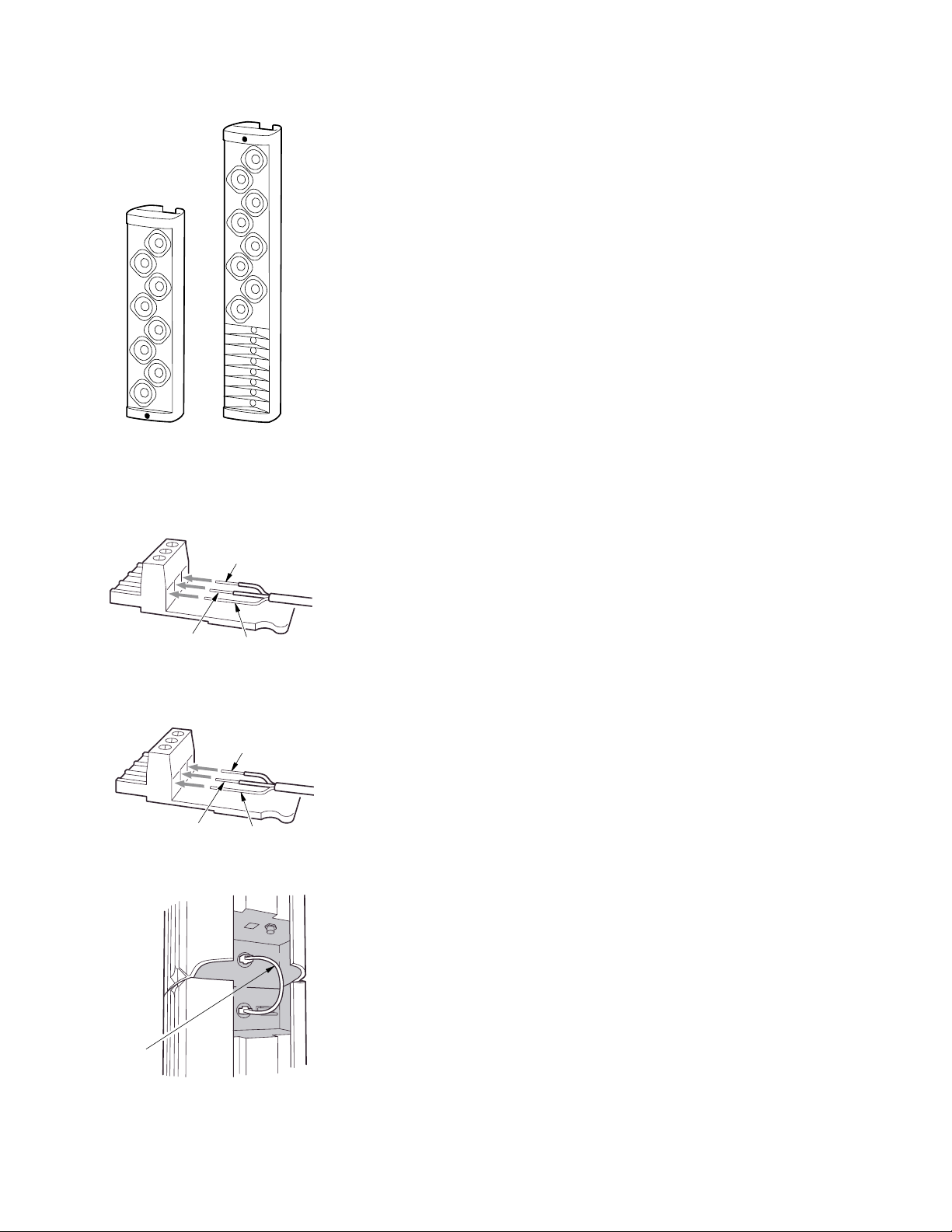
Figure 3.2 Audio Connector
Figure 3.1 DSA230 & DSA250
Figure 3.3 EIA-485 Connector
Figure 3.4a Signal Links < 1 ft / 0.3
AUDIO –
AUDIO +
SIGNAL +
LINK
CABLE
P/N
0005854
SHIELD
SIGNAL–
SHIELD
Page 9
Over 2 ft / 0.6 m: 2-conductor shielded audio cable / supplied Phoenix
Contact terminal block plugs
Connect Audio A, Audio B (if used), and EIA-485 in parallel daisy-chain
fashion between clusters.
3.5 AC Mains Installation
3.5.1 AC MAINS SUPPLY
Provide the loudspeaker with a 50 Hz or 60 Hz AC Mains circuit
capable of:
100 V to 120 V 220 V to 240 V
DSA230 4 A 2 A
DSA250 8 A 4 A
Before applying power, ensure that the AC Mains voltage matches the
voltage rating on the loudspeaker.
DANGER: DO NOT APPLY 230 V MAINS POWER IF THE VOLTAGE
RATING ON THE LOUDSPEAKER IS 115 V. IMMEDIATE AND CATASTROPHIC DAMAGE TO THE LOUDSPEAKER WILL RESULT AND
MAY CAUSE A FIRE HAZARD, SERIOUS PERSONAL INJURY, OR DEATH.
3.5.2 AC MAINS CABLE
Supply and connect #14 AWG / 2.5 mm power cable and appropriate
AC Mains plug to the supplied Neutrik/PowerCon® connector.
3.6 Physical Installation
3.6.1 ORIENTATION
1. When installing the enclosure, there is a
correct “top” and “bottom”. This cannot
be assumed from the physical appearance.
Instead, orientation depends on application
and desired acoustical performance
determined using the DSAPilot.
2. Ensure the enclosure is oriented correctly by
verifying which ends are supposed to be the
top and bottom for the intended application.
The Signal End is the end with the
identification LED, visible on one end
of the front of the enclosure. The Power
End has the AC Mains connector.
Note: The desired coverage cannot be gained
if the enclosure is incorrectly oriented.
3.6.2 MOUNTING
WARNING: Comply with all installation warnings in Section 5.5.1.
The DSA Series loudspeakers are normally intended to be flushmounted against a vertical surface capable of supporting their weight.
1. Using the template printed on the shipping box, locate and
position the supplied Wall Brackets to structure.
9
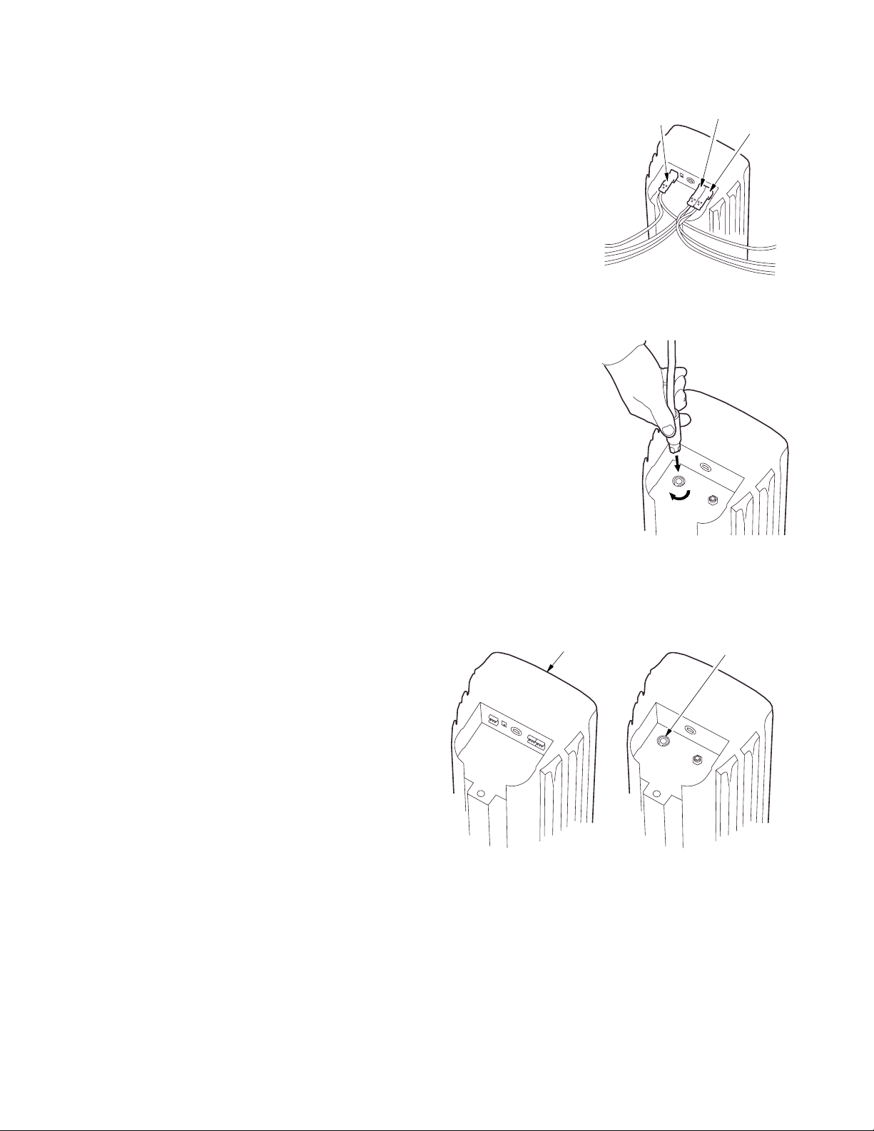
Figure 3.4b Signal Links >2 ft / 0.6 m
Figure 3.5 Connecting AC Mains
LED INDICATOR
ON FRONT SURFACE
POWER END
SIGNAL END
AC MAINS CONNECTOR
Figure 3.6 Signal End / Power End
EIA-485
AUDIO A
AUDIO B
Page 10
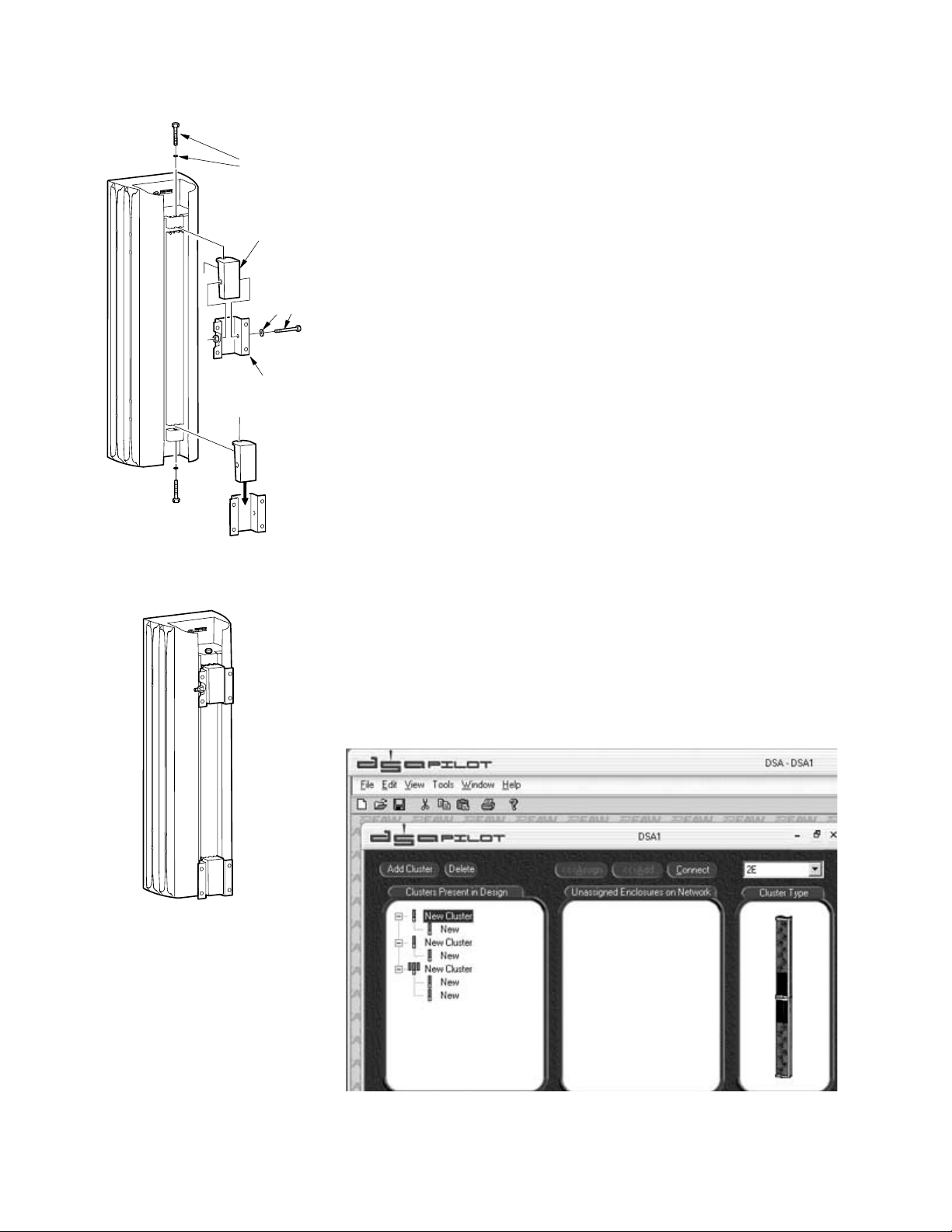
2. Attach the Wall Brackets to structure. You must provide attachment
hardware and ensure the attachment method and structure are
capable of supporting the intended load. Position the Wall Bracket
weld nuts left or right to allow clearance for later insertion of the
Retainer Bolt.
3. Ensuring they are oriented properly, install the two Enclosure
Brackets on the loudspeaker. Insert and hand-tighten the supplied 3/8-16
Enclosure Bracket Bolt and Lock Washer for each Enclosure Bracket.
4. Lift the enclosure onto the installed Wall Brackets.
WARNING: Use at least two people for lifting enclosure onto the
brackets.
5. Insert and snugly tighten at least one of the supplied 1/4-20 Retainer
Bolt and Lock Washer through the side of either of the Wall and
Enclosure Brackets. This prevents the enclosure from being lifted off
the Wall Brackets.
6. Securely tighten each 3/8-16 Enclosure Bracket Bolt to lock the
enclosure at the desired horizontal angle.
3.7 Signal Processing
The vertical coverage is determined by programming the loudspeaker’s
digital signal processing.
Use the DSAPilot to determine the desired coverage. The DSAPilot calculates
and optimizes the signal processing required to achieve the desired results.
High pass/low pass filters, parametric EQ, delay, and gain are user adjustable
for each of the two inputs.
10
2X 3/8-16 X 2 LG
Figure 3.6.2a Bracket Installation
Figure 3.6.2b Installed Bracket
Figure 3.7 DSAPilot Main Screen
BLACK HEX HEAD
ENCLOSURE BRACKET
BOLT & LOCK WASHER
2X ENCLOSURE
BRACKET P/N 0006118
1/4-20 X 3 LG
HEX HEAD
RETAINER BOLT
& LOCK WASHER
2X WALL BRACKET
P/N 0006119
Page 11
Chapter 4 Description
4.1 System Overview
DSA Series loudspeakers are variable directivity, self-powered line arrays. Each
loudspeaker’s vertical beamwidth is determined by the settings of an internal
DSP (digital signal processor) and power amplifier for each transducer. This
provides complete, on-site control over the range of possible vertical
beamwidth patterns.
EAW’s Windows-based DSAPilot is used to set the coverage required for each
loudspeaker or loudspeaker cluster. The user-friendly DSAPilot optimizes the
required signal processing for the design. This data is then uploaded to the DSA
Series loudspeakers in the system. The DSAPilot normally communicates with the
loudspeakers using EIA-485*. An optional CobraNet™ network interface is available.
*Formerly known as RS-485 (Recommended Standard 485)
4.1.1 DSA SERIES MODELS
DSA250: Full range, 2-way, loudspeaker system
DSA230: Low frequency and voice-only loudspeaker system
4.1.2 ACOUSTICAL BENEFITS
Each loudspeaker can be electronically adjusted on-site to direct sound
primarily where needed. Unwanted sound reflections from room
surfaces can be reduced, improving the direct to reverberant sound
ratio. This, in turn, can significantly increase speech intelligibility.
Asymmetrical pattern control can provide consistent SPL in situations
with HIGH near-to-far listener distance ratios. User adjustable level
control, equalization, and compression, are provided on each of the
two audio inputs. For situations with multiple locations, overall signal
delay for each loudspeaker cluster is also provided.
4.1.3 PHYSICAL BENEFITS
The DSA Series loudspeakers are physically narrow and quite shallow,
providing a low profile to reduce their impact on architecture. Their
normal mounting position is specifically designed to be flat against a
vertical surface. This considerably reduces installation complexity. The
DSA Series design permits several loudspeakers to be easily arrayed in
one location as a cluster. This affords additional capabilities including
higher output and extremely narrow vertical coverage, as well as extended
pattern control, and output at lower frequencies.
DSA Series enclosures are constructed of a powder-coated, extruded
aluminum body (also used as the amplifier heat sink), high-impact
polystyrene end caps, a thick PVC baffle, and a finely perforated
steel grille. This construction is designed for years of trouble-free
use. The appearance is designed to blend attractively with a variety
of architecture. The enclosure finish is a neutral white. The grille is
powder-coated steel, with a perforation style that appears similar to a
cloth grille at typical in-use distances. Installation hardware is included to
facilitate installation in most applications.
11
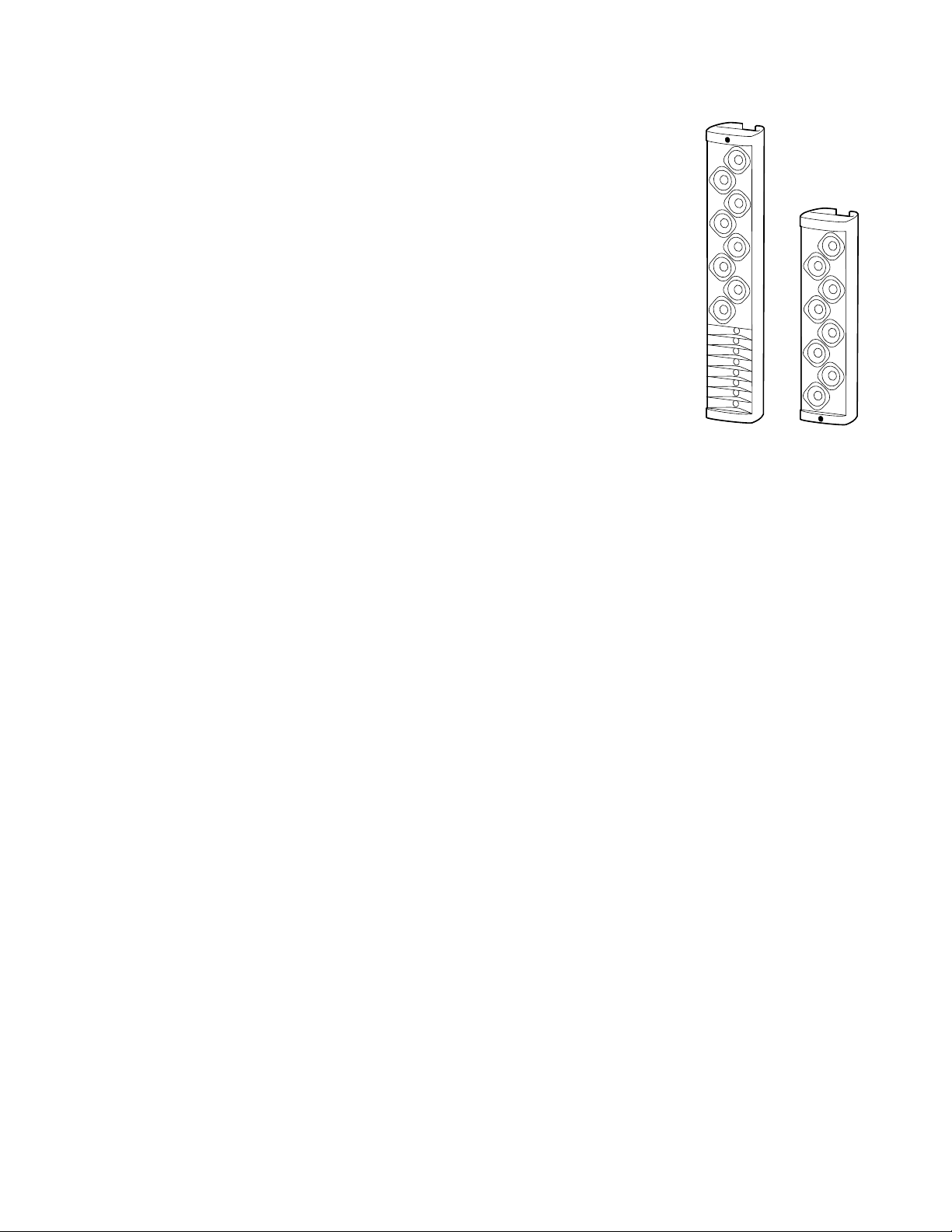
Figure 4.1.1 DSA250 & DSA230
Page 12
4.1.4 ELECTRICAL BENEFITS
Built in digital signal processing, power amplification, and protective
limiting significantly reduces equipment costs, space, installation,
and set-up adjustments. Cabling is limited to providing AC mains, line
level audio, and computer control signals. EIA-485 or optional
CobraNet™/Ethernet networking technology allows all loudspeakers in a
project to be adjusted and controlled from one computer. EIA-485
network topology was chosen as the supplied default because it is easy
to implement. It is also unique in allowing multiple network nodes to
communicate bi-directionally over a single pair of twisted wires. No
other network standard combines this capability with equivalent noise
rejection, data rate, cable length, and general robustness.
4.2 Features
4.2.1 ACOUSTICAL
·Vertical beamwidth is software controlled on-site to fit the application
·Wide 120 degree fixed horizontal beamwidth
·Pre-determined templates for loudspeaker clusters provide a wide
range of capabilities
·DSA250 full-range loudspeaker has eight 4 in LF drivers, eight 1 in
horn-loaded HF drivers
·DSA230 low frequency or voice-only loudspeaker has eight 4 in LF drivers
·Full frequency response and high output for music applications
·Extended pattern control and higher outputs at lower frequencies
using additional DSA230’s
·Exceptional intelligibility for reverberant rooms
4.2.2 ELECTRONIC
· Self-powered requiring wiring for AC power, line level audio, and
computer control
· No amplifier or processing racks needed, reducing space and cost
· Individual amplifier and DSP for each transducer
· Convection cooled electronics eliminates noisy cooling fans
· Built-in driver protection provides high reliability
· Two audio inputs allow summed stereo or priority announcement
override capability
· Electronically balanced inputs maximize the signal to noise ratio
4.2.3 COMPUTER CONTROL
· User-friendly DSAPilot software easily creates desired vertical
coverage patterns
· DSP adjusted and optimized by DSAPilot for plug and play setup
· User adjustable input EQ, signal delay, level, HPF/LPF, and
compression for each loudspeaker cluster
· Computer can be disconnected for no-tamper operation
· Computer can be left connected for monitoring purposes
4.2.4 NETWORKING
· EIA-485 network for remote PC operation and computer control
· Analog audio and control signals can be daisy-chained to multiple
loudspeakers
12
EIA-485
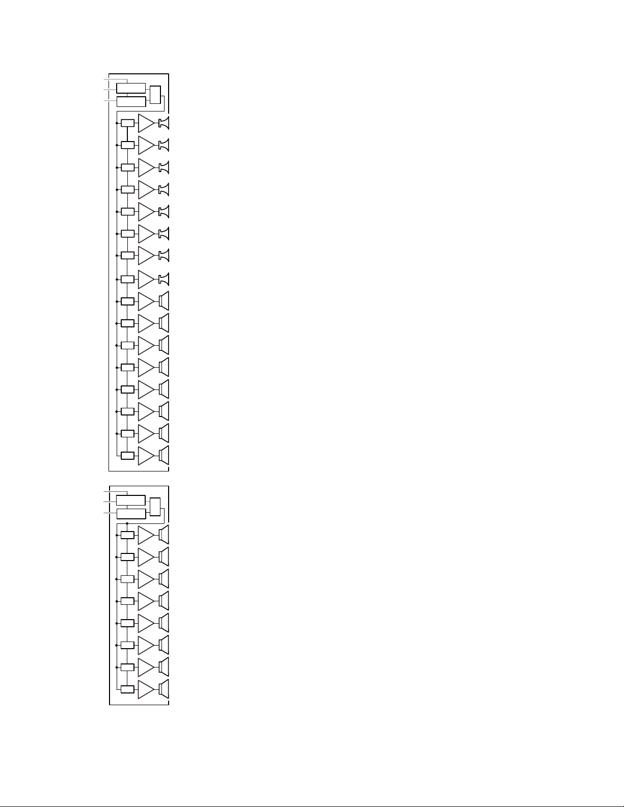
Figure 4.1.4 DSA Block Diagrams
AUDIO A
AUDIO B
INPUT DSP
INPUT DSP
DSP
DSP
DSP
DSP
DSP
DSP
AMP
AMP
AMP
AMP
AMP
AMP
DSA250
∑
EIA-485
AUDIO A
AUDIO B
DSP
DSP
DSP
DSP
DSP
DSP
DSP
DSP
DSP
DSP
INPUT DSP
INPUT DSP
DSP
DSP
AMP
AMP
AMP
AMP
AMP
AMP
AMP
AMP
AMP
AMP
DSA230
AMP
AMP
∑
DSP
AMP
DSP
AMP
DSP
AMP
DSP
AMP
DSP
AMP
DSP
AMP
Page 13

·Cat-5 Link Cable links adjacent loudspeakers.
·Optional CobraNet™ interface for digital distribution of audio and
computer control via Ethernet
·Provision for back up audio/computer communications using a
redundant Ethernet network, when using CobraNet™.
4.2.5 PHYSICAL
· Phoenix Contact and Neutrik EtherCon and PowerCon connectors
for reliable connections
· Low weight (<100 lb / 45 kg) reduces structural mounting requirements
· Mount vertically while providing asymmetrical down-angle coverage
· Brackets supplied for mounting to vertical surfaces
· Mounting allows +/-15 degree horizontal rotation of the enclosure.
· Optional hardware for suspending enclosures
· Elegant enclosure design and neutral color blends with a variety of
architecture
· Rear enclosure extrusion channels can be used to route cabling
4.3 Applications
The DSA Series provides a significant advance for cost-effective
implementation of line array technology in a variety of applications. As is
typical for line arrays, the DSA Series is an excellent choice for voice-only
applications. However, unlike typical voice-only line arrays, the DSA Series
can also provide the wide frequency range, fidelity, and output levels
needed for excellent music reproduction. This significantly extends its
range of applications to a wide range of venue types including theaters,
theme parks, retail spaces, and government facilities. Its unique
capabilities, however, make it particularly well suited to applications that
present a challenging acoustical, physical, or aesthetic environment.
The DSA Series is ideal for a variety of venues where achieving good vocal
intelligibility is critical. These include theatres, auditoria, houses of
worship, theme parks, retail spaces, government facilities, lecture halls,
large conference rooms, museums, and shopping malls. It can solve
acoustically difficult challenges in reverberant environments such as
cathedrals, concert halls, ballrooms, rail/air/sea terminals, large lobbies,
and athletic buildings. Its low profile further enhances its applicability in
aesthetically sensitive environments.
Designers can use DSA loudspeakers in a variety of factory-supported DSA
cluster configurations to meet specific output or directivity needs. For
voice-only applications, single DSA250 loudspeakers can be placed to
provide adequate output and horizontal coverage. In these cases, designers
enjoy control of the vertical pattern throughout the vocal range. For
broadband music reproduction, the addition of a DSA230 to each DSA250
will extend pattern control well into the LF range and provide additional
LF output.
Although the DSA Series is not specifically outfitted for outdoor
installations, its exterior components are inherently weather-resistant. If
suitably protected from direct exposure to weather, permanent outdoor
installation is possible, though is not recommended.
13
Page 14
4.4 Engineering Design
The core acoustical design of the DSA Series dates back to the late 1930s in
Harry Olson’s book, “Acoustical Engineering”. He showed that, by using
different signal delays on the input to each transducer in a simple line array,
the array’s main output lobe could be effectively “steered”. While this
concept has certainly been used before, the design of the DSA Series goes far
beyond this simple concept.
The engineering design for the DSA Series is certainly capable of “steering”
the main output lobe, as per Olson. However, the shape of the lobe in the
vertical plane is also variable. This allows changing the depth of the
coverage to precisely fit the listening area thereby reducing troublesome
near-to-far SPL differences.
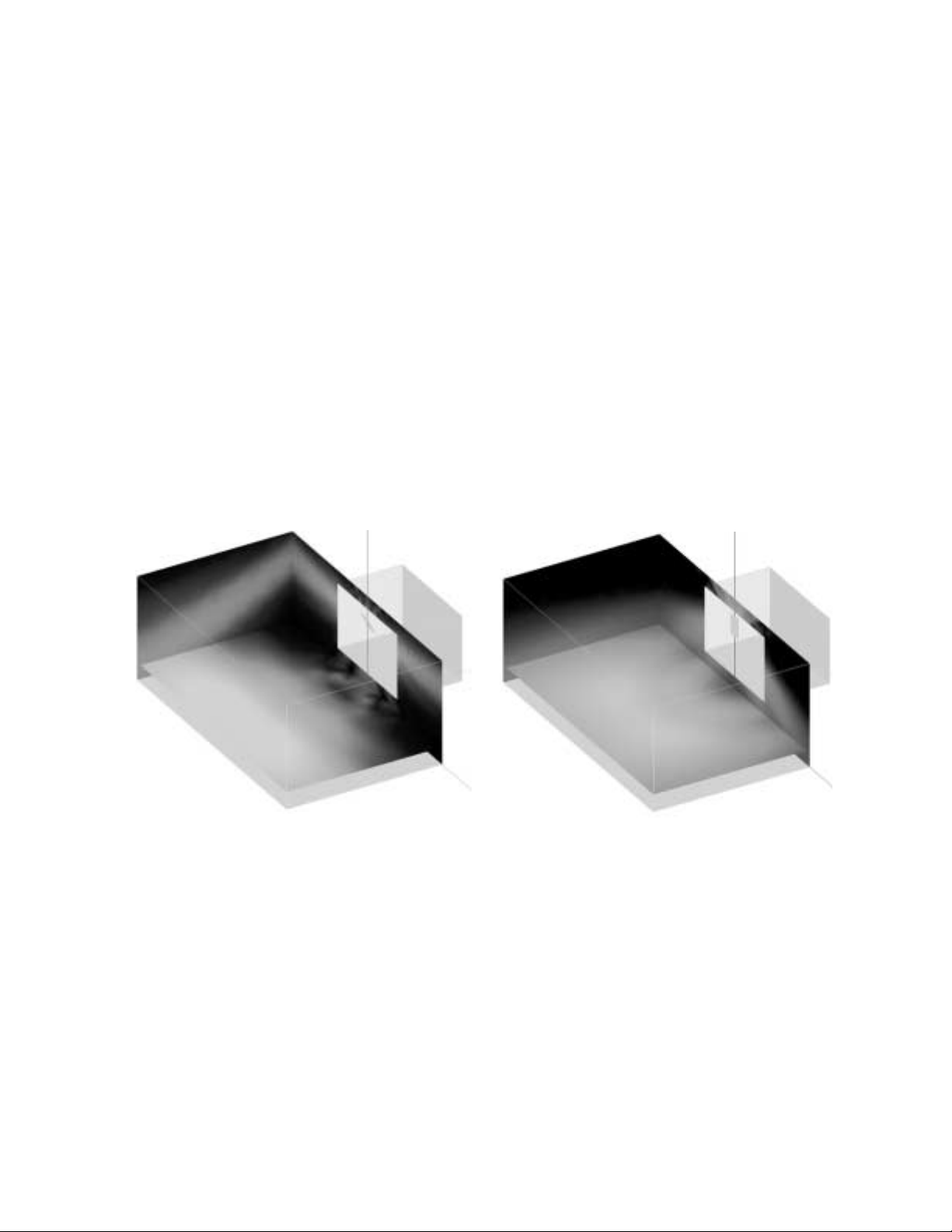
A major advantage of DSA is the character of its radiation pattern. Contrary to
what might be intuitively assumed, the DSA’s radiation pattern is not the same
as simply down-tilting a loudspeaker that has the same horizontal and vertical
beamwidths. The example EASE plots illustrate this difference.
The radiation pattern of the conventionally, down-tilted loudspeaker has at
least two problems. The geometry of the pattern results in inadequate
coverage across the front area of the room. It also focuses a distinct line of
energy along the side wall. This energy is nearly at the same loudness as the
floor seating area. The sound reflections off the upper part of the wall will
arrive at many listeners late enough to impair intelligibility. These
reflections add to the direct sound and cause the higher intensity sound
seen at the rear , even though these areas are further from the loudspeaker.
By contrast, the radiation pattern of the DSA loudspeaker is far more consistent
across the entire floor area. The energy it directs to the sidewalls is not only
lower in level, but creates a very different reflection pattern. The sound reflected
off the wall will be largely directed down into the floor or nearby listeners along
the sides, arriving early enough to actually enhance intelligibility.
14
Ver: 30° Hor: 120°
Lspk: S1
Project: DSAMultipurpose-Tilt
Map: Direct SPL
Freq: 5000 Hz
[Third Octave Average]
Shadow Cast: No
Resolution = 1.0 m
Ver: 30° Hor: 120°
Lspk: S1
Project: DSAMultipurpose-Steer
Map: Direct SPL
Freq: 5000 Hz
[Third Octave Average]
Shadow Cast: No
Resolution = 1.0 m
Figure 4.4a Angled Radiation Pattern
Figure 4.4b DSA Steered Radiation Pattern
Page 15

The required signal processing, accomplished by DSP (digital signal
processing), involves parametric equalization, signal delay, frequency
filtering, gain, and limiting. These parameters are individually adjusted by
the DSAPilot for each transducer in each loudspeaker. The available DSP
resources provide a broad range of possible coverage patterns and SPL
control over distance as well as the “voicing” required for exceptional
music reproduction.
The DSA allows multiple loudspeakers to be arrayed as a cluster at a single
location. This allows a greater range of beamwidths, SPL, pattern control,
and low frequency output than a single DSA loudspeaker can provide. The
DSAPilot treats the cluster as if it were a single loudspeaker, precluding the
complexities normally associated with designing clusters.
4.5 DSAPilot
The DSAPilot, used to set the loudspeaker signal processing parameters, is
based on software originally developed by EAW engineers for the KF750,
KF760, and, in particular, the KF900 Series products. These products
require precise but variable pattern control and a high degree of fidelity for
speech and music in projects that range from small houses of worship to
the newest super-stadiums. Sophisticated mathematical algorithms were
developed to determine the necessary adjustments to achieve these results
for both multiple transducers and multiple loudspeaker clusters. This math
was incorporated into highly user-friendly software. Thoroughly tested and
refined in successful, real-world applications, these techniques have been
applied to the DSA Series to achieve the same high degree of pattern
control, musicality, and ease of setup.
Though highly complex, the DSAPilot’s mathematics work behind the
scenes. Because of this, the DSAPilot makes adjusting the signal processing
deceptively simple. In fact, no acoustical knowledge is required to set up
and adjust one or multiple DSA Series loudspeakers. The only information
needed for the DSAPilot to perform its magic is the physical layout of the
listening area, loudspeaker mounting location, and desired coverage area.
4.6 Low Frequency Performance
While the DSA250 is designed as a full-range loudspeaker, addition of the
companion DSA230 increases directionality, and output at lower frequencies.
DSA230s extend directional control to lower frequencies using classical line
array theory by extending the length of the overall array. This is done by
mounting the DSA230 directly below or above a DSA250 to form a longer line
of low frequency transducers. In addition, the increased number of low
frequency transducers couple to increase the low frequency output capability.
4.7 Comparison to Traditional Products
A major benefit of the DSA Series is achieving desired down angle coverage
from a line source that is mounted flat to a vertical surface. The inclusion
of power amplifiers and dedicated signal processing to each transducer
provide the DSA Series with performance and capabilities well beyond
those of typical multi-way loudspeakers and traditional, voice-range line
arrays. The DSA Series can provide much better directional control, higher
output, and wider frequency response at less cost. Significantly smaller
sizes and weights, plus straightforward mounting and wiring options pay
15
Page 16

additional benefits in reduced installation costs and operation. The
flexibility of the DSAPilot to automatically optimize the acoustical
performance for multiple DSA Series loudspeakers in a single larger space
further enhances their advantage over traditional solutions.
4.8 Designing DSA Systems
DSA loudspeakers can be used individually, in multiples, or in various
cluster configurations to satisfy a wide range of design requirements. By
using different configurations, DSA performance can be varied according to
the type of audio program, the frequency range for the vertical control
desired, the maximum output levels, the audience location relative to the
loudspeaker, and for meeting the requirements for special applications.
Chapter 5 Installation
This chapter details the requirements for installing the loudspeaker.
Specific details may require some variation depending on the particular
situation. However, the basic requirements are the same in all cases.
Loudspeaker refers to either a DSA230 or DSA250.
Cluster refers to any of the permissible arrangements of single or multiple
DSA230s or DSA250s as defined in DSAPilot. Whether they consist of a single
or multiple loudspeakers, all DSA clusters function as a single loudspeaker.
5.1 Electrical Installation
This section details the electrical requirements for installing
the loudspeaker. Specific cabling details may require some
variation depending on the particular situation. However, the
basic requirements are the same in all cases.
Basic electrical installation tasks include:
Audio signal connection
Computer control connection
AC mains connection
5.1.1 CABLE ROUTING CONSIDERATIONS
The configuration and orientation of the loudspeakers will determine
where signal, computer, and AC mains cabling must be connected to
the loudspeakers. For certain cluster configurations it may be necessary
to route cabling from one end of a loudspeaker to another.
The main cable routing method is to use the channels in the heat sink
extrusion that forms the rear of the DSA250 and DSA230 enclosures.
These channels are intended to be used to route and conceal cabling
the length of the enclosure as required. In this way, single wall outlet
locations for audio, computer, and AC mains can easily service a single
loudspeaker or loudspeaker cluster.
To facilitate cable routing, clusters have been arranged, where possible,
so the Power Ends of the enclosures are adjacent. This minimizes the
routing of AC mains cables, which are heavier and more difficult to
thread into the extrusion than signal cables.
16
O
A
S
N
A
S
Figure 5.1 Electrical Block Diagram
Figure 5.1.1 Cable Channels
LINE LEVEL
AUDIO
SOURCE(S)*
PC*
*SUPPLIED BY THE USER
AC MAINS*
(115V OR 230V)
AUDIO A CABLE*
AUDIO B CABLE (IF USED)*
RS-232
TO EIA-485
CONVERTER*
EIA-485*
CABLE
CABLE CHANNELS
SIGNAL LINK CABLE T
ADJACENT DS
LOUDSPEAKER
DAISY-CHAI
CABLE TO DS
LOUDSPEAKER
DSA
SIGNAL LINK
CABLE TO
ADJACENT DSA
LOUDSPEAKERS
Page 17

5.1.2 AUDIO SIGNAL CONNECTION
CobraNet™: Skip to Section 5.2 if using CobraNet™ for distribution of
the audio and control signals.
Audio A
or
Audio B: 2-conductor twisted pair, shielded, audio cable connected
to supplied 3-pin Phoenix Contact Terminal Plug and to
the line level audio signal source.
Nominal level: 0 dBu / 0.775 V rms.
Recommended Conductor Gauge:
24 AWG to 18 AWG / 0.2 mm to 1 mm
Audio A
and
Audio B: As above but 4-conductor twisted pairs
5.1.3 COMPUTER CONTROL CONNECTION
CobraNet™: Skip to Section 5.2 if using CobraNet™ for distribution
of the audio and control signals.
EIA-485
(formerly
RS-485): 2-conductor twisted pair, shielded, cable connected to supplied
3-pin Phoenix Contact Terminal Plug and to EIA-485 port
for the computer.
Recommended Conductor Gauge:
24 AWG to 18 AWG / 0.2 mm to 1 mm
NOTES:
1. Do not combine EIA-485 and audio signals in the same cable.
2. An EIA-485 converter is required to convert a PC’s RS-232 or USB
port to a 2-wire EIA-485 port. While there are many converter
products available, contact EAW’s Application Support Group (See
Section 7.3) for recommendations about suitable models.
3. EIA-485 cabling has special requirements and limitations. See
Appendix 8.3 for details.
5.1.4 DAISY CHAINING COMPUTER AND AUDIO SIGNALS WITHIN CLUSTERS
WITH MULTIPLE LOUDSPEAKERS
NOTE: The Signal Link jacks carry both computer and audio
signals. The cable between the Signal Link jacks must be
wired as a standard Ethernet crossover cable. A cable wired as
a standard Ethernet straight through cable will not work.
1. Up to 1 ft / 0.3 m between adjacent over/under loudspeakers in a cluster:
Supplied Cat-5 Signal Link Cable
Connect between unused Signal Link jacks (Neutrik EtherCon) on
vertically adjacent ends of the loudspeakers.
2. Up to 2 ft / 0.6 m between adjacent side-by-side loudspeakers in a cluster:
User-supplied Cat-5 crossover cable.
Connect between unused Signal Link jacks (Neutrik EtherCon)
on horizontally adjacent ends of the loudspeakers.
17
LINK CABLE
P/N 0005854
Figure 5.1.4 Linking < 1 ft / 0.3 m
Figure 5.1.2 Audio A & Audio B
Figure 5.1.3 EIA-485 Connector
AUDIO –
AUDIO +
SHIELD
EIA-485
SIGNAL+
SHIELD
Crossover Cable Wiring
STANDARD END PINS 1 2 3 4 5 6 7 8
CROSSOVER END PINS 3 6 1 4 5 2 7 8
Page 18

5.1.5 DAISY CHAINING COMPUTER AND AUDIO SIGNALS BETWEEN CLUSTERS
Any distance (within EIA-485 limitations) between clusters:
2-conductor shielded cable
Audio A, Audio B, and EIA-485
Connect in parallel to the incoming signal cables on one loudspeaker
in the first cluster and connect to the same signal ports on one
loudspeaker in the next cluster. Use the supplied 3-pin Phoenix
Contact terminal plugs.
Recommended Conductor Gauge:
24 AWG to 18 AWG / 0.2 mm to 1 mm
5.1.6 EIA-485 TERMINATE SWITCH
EIA-485 termination has special requirements and limitations. See
Appendix 8.3 for details.
Single Cluster:
Set the EIA-485 Terminate Switch on the loudspeaker
(connected via the Phoenix connector) to “ON”.
Multiple Clusters:
Set the EIA-485 Terminate Switch to “ON” ONLY on the
loudspeaker (connected via the Phoenix connector) at the end of the
EIA-485 cable run furthest from the computer. Set all other Terminate
Switches to “OFF”.
CAUTION: Engaging the EIA-485 Terminate Switch on more than
one loudspeaker on the EIA-485 cable run can cause intermittent
or non-existent communications.
5.2 CobraNet™ Network Connections
This section provides details about using the optional CobraNet™
technology for distribution of audio and computer control signals.
5.2.1 DESCRIPTION
CobraNet™ is a combination software, hardware, and network protocol
that replaces the audio and computer connections described in Section
5.1. Digitized audio and computer control is distributed by a CAT-5
(or better) cable to each loudspeaker. The network infrastructure must
be designed using standard IEEE 802.3u 100BASE-T Fast Ethernet
hardware. The network will not function properly using 10BASE-T
technology.
5.2.2 COBRANET™ IS USUALLY DESIRABLE TO USE WHEN:
· A star cable configuration is easier to implement for multiple loudspeakers
· A high degree of noise immunity is needed for the audio
· Future system expansion is likely
· Long cable runs that permit fiber optic cabling
· Other CobraNet™-capable products are used in the same installation
· The number of loudspeakers and clusters exceeds 32
· The audio source(s) have digital outputs
18
EIA-485
Figure 5.1.5 Linking > 2 ft / 0.6 m
Figure 5.1.6b EIA-485 Network Diagram
Figure 5.1.6a EIA-485 Terminate Switch
AUDIO A
AUDIO B
EIA-485 TERMINATE SWITCH
ON
EIA-485
TERMIN
A
AUDIO
GROUND
LIFT
OFF
TE
LIFT
DSA
CLUSTERS
PC
RS-232
OR USB
TO EIA-485
CONVERTER
TERMINATE
SWITCH "OFF"
TERMINATE
SWITCH "OFF"
TERMINATE
SWITCH "ON"
Page 19

5.2.3 ADDITIONAL EQUIPMENT YOU MUST SUPPLY FOR COBRANET™ :
· Loudspeaker interface:
EAW CM-1 CobraNet™ Interface Card (P/N 0005987)
for each DSA Series loudspeaker
· Audio/Computer interface:
Converts signals to CobraNet™ protocol
· Ethernet switch or hub:
For networking multiple loudspeakers over Ethernet
5.2.4 CABLING:
A CAT-5 or better cable with RJ-45-compatible connectors is required
for each loudspeaker.
NOTE: Ethernet cable length is limited by specification to 328 ft / 100 m.
Longer runs are possible using network hubs or switches as repeaters or
by conversion to fiber optic cable.
5.2.5 AUDIO/COMPUTER INTERFACE:
Audio and RS-232 (for the DSAPilot control signals) must be converted to
the CobraNet™ protocol and connected to the network via an RJ-45 Ethernet
port. Products that do this are available from several manufacturers. Your
choice will depend, in part, on how many and what form of audio signals
(digital or analog) you need to distribute.
Manufacturers of converters include:
Peavey, QSC, Rane, Symetrix, Whirlwind, and Yamaha.
5.2.6 LOUDSPEAKER INTERFACE:
An optional EAW CM-1 CobraNet™ Interface Card must be installed in
the slot provided in loudspeaker. To do this, see installation instructions that accompany the CM-1.
Connect the PRIMARY RJ-45 Ethernet connector to the Ethernet cable.
The SECONDARY RJ-45 Ethernet connector on the CM-1 is for connecting to a second, redundant Ethernet network. This would be designed
as a back-up network that automatically takes over in the event of
failure in the primary network.
The digital audio received by the CM-1 connects directly to the loudspeaker’s digital signal processing. It is converted back to analog at the
inputs to the internal power amplifiers.
5.2.7 MULTIPLE LOUDSPEAKERS:
To connect multiple loudspeakers to the network, the Ethernet output
on the audio/computer interface must connect to a network switch or
hub. A network switch is normally recommended. The switch must
have an Ethernet port for each loudspeaker.
A CAT-5 cable is required from the Ethernet port on the CM-1 Interface
Card in each loudspeaker to its port on the network switch. For networks requiring cable runs longer than 328 ft / 100 m, a repeater
network or fiber optic cabling is recommended. Do NOT mix hubs and
switches on a repeater network. Network switches and hubs are available through most computer retailers.
5.2.8 SUPPORT FOR COBRANET™ / ETHERNET
See Sections 8.4 and 8.5 for support information for Ethernet and CobraNet™.
19
Figure 5.2.6 CM-1 Interface Card
(See Installation Instructions with Card)
CAT-5
CABLES
MAX 328
ft/100 m
100BASE-T
NETWORK
SWITCH
DSA
LOUDSPEAKERS
WITH
OPTIONAL
CM-1 CARD
AUDIO/COMPUTER
INTERFACE
PC
LINE LEVEL
AUDIO
SOURCE(S)
Figure 5.2.3 Basic CobraNet™ Diagram
4X FLAT
HEAD
SCREWS
CM-1 INTERFACE CARD
Page 20

5.3 AC Mains Power Connection
This section details the requirements for the AC mains which is the AC
power connection required by each DSA loudspeaker.
5.3.1 AC MAINS SUPPLY
CAUTION: Read all cautionary notes concerning electrical power in
Chapter 1.
Each DSA Series loudspeaker is rated for a particular nominal AC Mains
voltage: 115 V or 230 V. Provide the loudspeaker with 50 Hz or 60
Hz AC Mains circuit capable of:
100 V to 120 V 220 V to 240 V
DSA230 4 A 2 A
DSA250 8 A 4 A
Before applying power, ensure that the AC Mains voltage matches the
voltage rating on the loudspeaker.
DANGER: DO NOT APPLY 230 V MAINS POWER IF THE VOLTAGE
RATING ON THE LOUDSPEAKER IS 115 V. IMMEDIATE AND CATASTROPHIC DAMAGE TO THE LOUDSPEAKER WILL RESULT AND MAY
CAUSE A FIRE HAZARD, SERIOUS PERSONAL INJURY, OR DEATH.
5.3.2 AC MAINS CABLE
The supplied Neutrik PowerCon NAC3FCA plug mates with the Neutrik
PowerCon NAC3MPA AC MAINS jack on the loudspeaker. Because of
both varying installation and electrical code requirements, neither an
AC Mains cable nor AC mains supply connection are supplied.
1. Supply and connect a 3-conductor power cable to the supplied
PowerCon plug, ensuring a proper ground connection.
2. Supply and attach an appropriate connector for the AC Mains
connection at the other end.
Recommended Power Cable
Conductor Gauge: 14 AWG / 2.5 mm (limited by PowerCon design)
Cable O.D.: 5 mm to 15 mm (limited by PowerCon design)
Recommended
length: Maximum 25 ft / 8 m (for <2% voltage drop at
peak input power)
NOTE: If the power cable is longer than 25 ft / 8 m the voltage drop
will increase.
5.3.3 POWER ON / OFF
There is NO power on/off switch on DSA Series loudspeakers. The
loudspeaker will be powered on (energized) when connected to an AC
mains supply. The LED on the “Signal End” will flash rapidly for about
3 seconds when first powered on. This is normal and indicates the
electronics are being initialized.
20
Figure 5.3.2 PowerCon Plug
GROUND
L
N
NEUTRIK
POWERCON
PLUG NAC3FA
Page 21

The LED should then go off. See Section 6.1.2 for other LED indications.
If it is desired to completely power off (de-energize) the loudspeaker,
a conveniently located AC mains disconnect must be supplied or
the power cable must be unplugged from the loudspeaker or the AC
mains supply.
The PowerCon connector is a locking connecter. To lock, twist 1/4 turn
clockwise after fully inserting into the jack. It is recommended the
connection be made at the loudspeaker before connection to the AC
mains supply.
5.3.4 AC MAIN FUSE:
If excessive AC mains input current is detected, the replaceable fuse will
blow. This can occur for a variety of reasons, such as internal failure,
excessive AC mains voltage, or excessive amplifier output levels.
If the fuse blows, replace it only with a fuse of the correct type and
rating as listed below. In the unlikely event the fuse blows again, internal failure is indicated. This will require troubleshooting and repair
by a qualified service technician. Do not attempt further use of the
loudspeaker until such repairs are made. See Section 8.2 “Troubleshooting”.
Fuse Type: AGC (0.25 in x 1.25 in) slow-blow
Rating: 115 V AC 230 V AC
DSA230 4 A 2 A
DSA250 8 A 4 A
5.4 Grounding
5.4.1 ELECTRICAL GROUND
Ensure that the AC mains grounding conductor in the power cable is
properly grounded in accordance with applicable electrical codes.
5.4.2 AUDIO GROUND
The Audio Ground Lift switch may help isolate audio ground loops.
This dip switch disconnects the shield pins on all the audio connectors
from the internal audio ground. This affects the audio shield pins on
the Audio A and Audio B connectors. Use this switch as needed for
reducing ground loop noise.
21
Figure 5.3.4 Fuse
Figure 5.3.3 Connecting AC Mains
H
Figure 5.4.2a Ground Lift Switch
Figure 5.4.2b Ground Lift Function
CAP
FUSE
HOUSING
POWER END
GROUND LIFT SWITC
ON
EIA-485
AUDIO
GROUND
LIFT
OFF
LIFT
TERMINATE
SIGNAL END
2X
AUDIO
SHIELD
PINS
AUDIO A
PHOENIX
CONNECTORS
AUDIO B
EMI
FILTER
EMI
FILTER
CHASSIS/MAINS
GROUND
AUDIO
GROUND
LIFT
SWITCH
LIFT
AUDIO
GROUND
Page 22

5.5 Physical Installation
This section details the physical requirements and methods for installing
the loudspeaker. Specific mounting procedures detailed herein may require
some variation depending on the particular situation. However, the basic
methodology is the same in all cases.
Basic installation tasks include:
Installing the Enclosure and Wall Brackets
Mounting the loudspeaker
5.5.1 INSTALLATION WARNINGS
DANGER: DSA Series loudspeakers must be securely mounted to structure capable of supporting their weight. The user is responsible for
providing properly engineered attachment of the supplied Wall Brackets
to structure, using hardware rated for the load. Failure to follow this
warning may result in failure of the mounting causing the loudspeaker to fall down, with possible equipment damage, injury, or death.
DANGER: Only persons with the knowledge of proper hardware and
installation techniques required should attempt to install DSA
Series loudspeaker systems overhead. Failure to follow this precaution may result in damage to the equipment, injury, or death.
CAUTION: The actual coverage provided by a DSA Series loudspeaker
will be largely determined by the DSAPilot adjusting its signal processing
settings. However, the loudspeaker must still be positioned in a location that is within the possible adjustment range for the desired coverage.
CAUTION: It is physically possible to mount a DSA Series loudspeaker
either end up. Because of the transducer-specific signal processing, it
will NOT provide the desired performance if installed upside down in
its intended application.
CAUTION: For DSA Clusters with two or more loudspeakers mounted
one over the other, it is recommended to make all cable connections
before lifting each loudspeaker onto the wall brackets. See Sections 5.2
through 5.6. Once the loudspeakers are mounted, access to the
connectors may be difficult.
5.5.2 PHYSICAL ORIENTATION – SIGNAL END / POWER END
The directionality of the DSA Series loudspeakers partly depends on
using specific signal delays to each transducer to control its sound
arrival to the listeners. As such, the DSAPilot makes assumptions about
the physical location of each transducer in the enclosure. This means
there is a correct “top” and “bottom” to each enclosure that is specific
to each application.
The two ends of DSA loudspeakers are referred to as the Signal End and
Power End. In addition to this physical difference, there is a built-in LED
indicator on the front of the Signal End of each loudspeaker. The orientations are shown in the DSAPilot graphics. When activated by the DSAPilot
software, this LED can be used to verify both the correct up-down
orientation and, when multiple loudspeakers are used, the correct
location of each. For the DSA250, the Power End is the end with the
HF subsystem and Signal End is the end with the LF subsystem.
22
LED INDICATOR
Figure 5.5.2 Signal End / Power End
ON FRONT SURFACE
SIGNAL END
AC MAINS CONNECTOR
POWER END
Page 23

5.5.3 MULTIPLE LOUDSPEAKERS AND CLUSTER CONFIGURATIONS
CAUTION: Only clusters defined by the DSAPilot or pictured herein may
be used. Any other configurations will result in poor to unusable performance. In the future other configurations may be added to the DSAPilot.
In some applications, tighter MF/HF pattern control, higher output, or
narrower vertical coverage may be desirable. Where higher LF output
capability is desired, height restrictions may not permit the ideal overunder mounting of the DSA250 and DSA230 models. Because of these
and other possible requirements, the DSAPilot allows several cluster
configurations to be used in a single or in multiple locations to
achieve various coverage and output results. See the DSA Application
Guide for details.
NOTE: Where aesthetics or other
considerations warrant, side-by-side
configurations can be mirrored
without affecting the results.
23
1A
1B
1C
2A
2B
2C
2D
2G
2F
3A
2E
Figure 5.5.3 DSA Cluster Configurations
Page 24

5.5.4 INSTALLATION OPTIONS
Normal Method: This method is for installing DSA loudspeakers
flush-mounted to a vertical wall surface using the supplied brackets. The
installation instructions herein apply to this installation method.
Optional Normal Method: This method is for suspending DSA
loudspeakers. The optional DSA Fly-Bar Kit is required for suspension. For
suspending more than one loudspeaker from a single Fly-Bar, the
optional Enclosure Connecting Kit is also required. These accessories are
supplied with complete instructions for their use.
Alternate Methods: In some applications, the DSA loudspeakers may
require suspension or other methods of installation. Please contact EAW
for assistance when the normal method cannot be used. (See Section 7.3)
Orient each enclosure in the cluster as shown in the DSAPilot diagrams
according to the location of the Signal End with the LED.
5.5.5 ANGLING ENCLOSURES
1. Vertical Angle: Normally, the DSA Series enclosures are designed to
be mounted flat to a vertical surface.
2. Horizontal Angle Single Loudspeakers: When mounted flat to a
vertical surface, the mounting hardware allows the enclosures to be
rotated up to +/-15° degrees horizontally, 0° being perpendicular to
the wall surface. This allows directing its fixed 120° horizontal
coverage anywhere within a 150° arc around the front of theloudspeaker.
3. Horizontal Angle Over/Under Loudspeakers: Always align over/under
enclosures so they are aimed in the same direction.
4. Horizontal Angle Side-by-Side Loudspeakers: These clusters cannot
be rotated horizontally. Always position the DSA250 and DSA230
loudspeakers for these clusters so that their aiming axes are
perpendicular to the mounting surface.
24
Figure 5.5.5a Horizontal Rotation
Single Enclosure
WALL
Figure 5.5.4a Wall Mounted
Figure 5.5.4b Suspended
DSA
SUPPLIED
WALL
BRACKETS
USER-SUPPLIED
SUSPENSION
HARDWARE
OPTIONAL
FLY-BAR KIT
DSA
OPTIONAL
ENCLOSURE
CONNECTING
KIT
DSA
15°
0°
15°
WALL
Page 25

5.5.6 MOUNTING HEIGHT
The acoustical reference point for the DSAPilot is the geometric
center of the cluster, which is halfway between the top of the top
enclosure to the bottom of the bottom enclosure. That means for a
steering angle of 0 degrees “on-axis” is the physical center of the cluster.
The elevation entered into DSAPilot refers to this point. This means
that if an elevation is entered that is less than half the height of the
cluster, it will go “through the floor” in the software.
For installation purposes, the mounting height of the bottom
enclosure in a cluster will be the cluster elevation as entered in
DSAPilot minus one-half the total physical height of the cluster
5.5.7 WALL BRACKET INSTALLATION
DANGER: Only persons with the knowledge of proper hardware and
installation techniques required should attempt to install DSA Series
loudspeaker systems overhead. Failure to follow this precaution may
result in damage to the equipment, injury, or death.
The supplied Wall Brackets are designed for attachment of the loudspeaker enclosure to a wall or other vertical surface. Ensure both the
attachment hardware and the architectural structure are capable of supporting the load with a design factor that meets applicable building codes.
Weights:
DSA230 63 lb / 28.6 kg
DSA250 90 lb / 40.0 kg
1. Using the supplied Wall Bracket Mounting Template or exact
measurements, locate the four mounting points required to attach
each supplied Wall Bracket to the supporting structure. Mounting
templates are provided on the shipping-carton and CD-ROM. A
bracket template is shown in chapter 9. Ensure that these mounting
points are plumb and square to each other so the enclosure will be
exactly vertical when installed. Being out of plumb and/or square
can prevent them from properly engaging the Enclosure Brackets
attached to the enclosure.
25
GOOD
Figure 5.5.5b Horizontal Rotation
Over / Under Enclosures
Figure 5.5.5c Horizontal Rotation
Side-by-Side Enclosures
Figure 5.5.6 Mounting Height
BAD
GOOD
BAD
ACOUSTICAL
REFERRENCE
POINT
("ON AXIS" )
MOUNTING
HEIGHT
FLOOR
C
L
Page 26

Critical Dimensions:
1. Spacing between the Wall Brackets for a single loudspeaker must be
within 0.1 in / 3 mm of the dimensions in Figure 5.5.7a.
In order to lift a loudspeaker onto its wall brackets, spacing between
the top wall bracket and ceiling, or other overhead obstruction,
must be 8.5 inches minimum. NOTE: 8.5 inches allows only 0.25
inches extra clearance.
2. Spacing between the Wall Brackets for loudspeakers mounted overunder fashion must be 4.9 inches.
3. Spacing between the Wall Brackets for loudspeakers mounted side
by side must be 5.4 inches.
4. Provide attachment hardware and secure the supplied Wall Brackets
to the mounting structure, complying with all Caution and Warning
notes in Section 5.5.1.
NOTE: The Wall Brackets have a weld nut on one side. Be sure to locate
this weld nut to the right or left such that the Retainer Bolt can be
inserted into the opposite side of the Wall Bracket after the loudspeaker
is mounted.
26
Figure 5.5.7b Over-Under Spacing
Figure 5.5.7c Side-By-Side Spacing
Figure 5.5.7d Wall Bracket Attachment
(For illustration purpose only. Attachment
hardware selection is installer’s responsibility.)
8.5 in MINIMUM TO CEILING
Figure 5.5.7a Wall Bracket Spacing
DSA250
38.1 in
968.3 mm
DSA230
23.9 in
606.3 mm
4.9 in
123.9 mm
5.4 in
136.6 mm
USER SUPPLIED
ATTACHMENT
HARDWARE
Ø 0.39 in
Ø 9.9 mm
Page 27

5.5.8 ENCLOSURE BRACKET INSTALLATION
Insert each supplied Enclosure Bracket into its slot near each end of the
enclosure, verifying the proper orientation of the enclosure. Insert a
supplied 3/8-16 x 2 in Enclosure Bracket Bolt with its lock washer into
each bracket bolt hole in the enclosure. Thread each bolt into the weld
nut on its Enclosure Bracket and hand-tighten.
CAUTION: Make sure the brackets are installed so the enclosure
orientation will be correct when the enclosure is mounted.
5.5.9 ENCLOSURE INSTALLATION
Lift the enclosure onto the structure-mounted Wall Brackets
DANGER: It is recommended that lifting the enclosure in place be
performed by at least two people to prevent it from falling during its
installation and causing possible equipment damage, injury, or death.
CAUTION: For DSA Clusters with two or more loudspeakers mounted
one over the other, it is recommended to make all cable connections
before lifting the loudspeakers onto the wall brackets. See Sections
5.2 through 5.6. Once the loudspeakers are mounted, access to the
connectors may be difficult.
IMPORTANT: When installing loudspeakers mounted vertically end to
end, install the lower loudspeaker first.
27
Figure 5.5.8 Enclosure Bracket Installation
Figure 5.5.9a Enclosure Installation
2X 3/8-16 X 2 LG
HEX HEAD SCREWS
& LOCK WASHERS
2X ENCLOSURE
MOUNTING
BRACKET
P/N 0006118
2X WALL
MOUNTING
BRACKET
P/N 0006119
Page 28

1. Install at least one of the supplied 1/4-20 X 3 in Retainer Bolt
with its lock washer through the side of either the top or bottom
Wall/Enclosure Bracket and snugly tighten. The bolt threads into a
weld nut on the side of the Wall Bracket. This Retainer Bolt prevents
the enclosure from being lifted off the Wall Brackets without first
removing the bolt. Note that the Retainer Bolt does not “clamp”
or support anything. It serves only to retain the enclosure on the
wall brackets, not to lock it into position.
2. Route cabling as required using the rear channels in the enclosures
extrusion.
3. Rotate the enclosure to the desired horizontal angle. Firmly tighten
each Enclosure Bracket Bolt to secure the enclosure in the desired
position.
28
1/4-20 X 3 L
G
W
R
Figure 5.5.9b Retainer Bolt Installation
Figure 5.5.9c Cable Routing
Figure 5.5.9d Secure the Enclosure Position
HEX HEAD SCRE
& LOCK WASHE
1/4-20 WELD NUT
CABLE CHANNELS
ENCLOSURE BRACKET BOLT
Page 29

5.6 Initial Set-Up
5.6.1 VERIFY LOUDSPEAKER ORIENTATION AND POSITION
Using the DSAPilot, and with communications established with the
loudspeakers, click on each loudspeaker in DSAPilot. The LED in
both the DSAPilot graphic and on the actual loudspeaker will
illuminate. Ensure that the physical orientation and position of
each loudspeaker corresponds to that shown in the DSAPilot graphic.
See the DSAPilot help file for further information.
CAUTION: Incorrect orientation or cluster position will result in poor
to unusable performance.
5.7 Acoustical Installation
Adjustment of the signal processing and thus the acoustical performance
for each DSA Cluster is accomplished using the DSAPilot program.
Complete instructions for its use can be found in the DSAPilot Help file.
These are the basic tasks that need to be done using the DSAPilot:
1. Select each cluster configuration used in the system design
2. Assign the installed clusters to those selected in the DSAPilot
3. Set the Steering parameters for each cluster
4. Configure the audio input routing for each cluster
5. Set the user-adjustable gain, EQ, compression, or signal delay for
the inputs
6. Set the desired Power Saving operation
7. Save the final signal processing settings for the system to a file
29
Figure 5.6 Identification LED
LED INDICATOR
Page 30

Chapter 6 Operation
The general operation of a DSA loudspeaker is similar to the operation of
most loudspeakers. Initial system set-up and overall tuning adjustments
detailed in this Chapter must be made using DSAPilot. For details about
using DSAPilot functions refer to the DSAPilot Help File. Performance
operation is largely concerned with adjusting the operating levels, avoiding
excessive input signals and, if needed, making in-performance “voicing”
adjustments using external equalization
These operation instructions assume that the loudspeaker has AC Mains,
audio signal, and computer control lines properly connected, and that they
are passing signals correctly.
6.1 Operational Functions
There are several, unique functions that affect and enhance operation.
These include Power Management, LED Indicator, and signal Monitoring.
6.1.1 POWER MANAGEMENT
The Power Management feature is a power saving function that
improves energy efficiency. This feature automatically puts the DSA
amplifiers into stand-by mode similar to a computer monitor. The
initiation of this mode occurs after the input signal is absent for a
period of time.
Enable or disable this function using DSAPilot. If enabled, the period
of time the input signal must be absent before entering stand-by is
adjustable. In addition, DSAPilot allows forcing the standby condition
should the need arise to de-activate the amplifiers without disconnecting
the AC mains.
6.1.2 LED INDICATOR
The LED Indicator located on the front of a DSA loudspeaker at the
“Signal End” can be set to indicate the status of several operating
conditions. Enable or disable each indication using DSAPilot. The
actual conditions monitored by the LED are not affected by enabling
or disabling the LED indication.
1. Initialization: The LED on the “Signal End” will flash rapidly for
about 3 seconds when first powered on. This is normal and
indicates the electronics are being initialized. The LED should
then go off. This indication is permanently enabled.
30
Page 31

2. Input Clip: If this indication is enabled, random flashing shows
that the audio input signal is clipping the A to D converters at
the input. To correct this condition, reduce the input signal level
at the source. Because the input gain is after the A to D converters,
the DSA input gain adjustment will have no effect on this condition.
NOTE: This is likely an unusual condition because the LED will
respond only if the input signal levels are greater than +24 dBu.
It is recommended that this function normally be disabled.
3. Output Compressor/Limiter Active: If this indication is enabled,
random flashing shows that the amplifier output compressor/limiters
have been activated. Occasional flashing is acceptable. Flashing
more than once every few seconds means the input signal level is
too high. To correct this condition during a performance, reduce
the input signal level at the signal source. If the source levels must
normally be run at such levels, then reduce the DSA input gain
using DSAPilot. Because of possible audio artifacts, this latter
adjustment should not be done during a performance.
NOTE: It may be desirable to disable this indication to avoid the
audience seeing flashing LEDs, particularly on dynamic program.
In this case, determine the source level that triggers the Output
Compressor/Limiters. Monitor and control the source level so as
not to exceed this pre-determined trigger level. This will help
prevent the DSA Output Compressor/Limiters from activating
more than occasionally.
4. System Error: If this indication is enabled, flashing at regular
intervals indicates a fault in the DSA’s electronics. Faults include
malfunctioning amplifiers or DSPs, over temperature, and low battery.
If a fault is indicated, use DSAPilot to determine the exact problem.
NOTE: A battery is used to retain the DSA’s settings when
disconnected from the AC Mains. A low battery requires
replacement by the EAW Service Department or the service
department of the EAW Distributor for your country. Expected
battery life is 10 years without being connected to the AC mains.
5. Identification: Using DSAPilot during initial system set-up, this
function is used to physically identify with which cluster DSAPilot
is communicating. Selecting a cluster or an individual loudspeaker
within a cluster in DSAPilot will turn on the LEDs in the
corresponding enclosures.
6.1.3 SIGNAL MONITORING
Real-time Input and output signal levels can be monitored using DSAPilot.
31
Page 32

6.2 Operational Check List
To operate a DSA loudspeaker, pre-performances checks and adjustments
should be made. In typical permanently installed applications, these
checks would normally be one-time, set-up adjustments that may only
need to be periodically verified. All of these steps require using DSAPilot.
1. Set the Power Management function as appropriate for your application.
2. Select each cluster in the DSAPilot design and verify the LED indicator
illuminates on the corresponding physical cluster.
3. Verify that the LED indicator on each enclosure is at the top or bottom
as shown in DSAPilot.
4. Adjust the input gain for each cluster for the desired nominal output
level for the expected input signal levels.
5. Adjust the input EQ for each cluster for the desired voicing to accommodate room acoustics, program content, or personal taste.
6. Adjust the input Limiting for each cluster to prevent higher than desired
output SPLs.
6.3 Normal Operation
6.3.1 POWERING UP
Power is applied to DSA in one of three ways:
1. Always On: Connect the loudspeaker to a continuously powered
AC mains supply. The loudspeaker is always ready for use. For
this mode, disable the Power Management function.
2. Off/On: Connect the loudspeaker to an AC mains supply which
is switched on and off between uses. The AC mains must be
switched on for each use. For this mode, disable the Power
Management function.
3. Standby/On: Connect the loudspeaker to a continuously powered
AC mains supply. The loudspeaker will be ready when input signal is
applied. For this mode, enable the Power Management function.
6.3.2 SIGNAL PROCESSING SETTINGS
When powered up, the signal processing in each loudspeaker will be set to
what it was for the previous use. The signal processing settings are
retained by non-volatile memory in each loudspeaker. This memory will
last indefinitely when connected to the AC mains. When disconnected
from AC mains, a battery supplies power to this memory. The expected
battery life without being connected to the AC mains is 10 years.
32
Page 33

6.3.3 OPERATION
Operate DSA similarly to any other loudspeaker. This normally involves
setting the source levels to achieve the desired output as well as
applying external equalization or other signal processing to achieve
certain desired results. DSA’s internal signal processing, set using
DSAPilot, should not be used for in performance adjustments.
6.4 Operational ‘ DOS’ and ‘DONTS’
6.4.1 EQUALIZATION
If equalization is required for tailoring the frequency response during
performances, use an external equalizer such as a good quality 1/3
octave graphic equalizer, for this purpose. Connect the equalizer inline with the DSA input signal. The DSA input equalization, adjusted
via DSAPilot, should be used only for overall tuning adjustments
made during initial system set-up.
6.4.2 MAXIMUM OUTPUT
At the highest usable operating levels, the LED Indicator on the
loudspeaker and in the level meters in DSAPilot should show no
more than occasional clipping. Occasional clipping means the LED
indicator, if enabled, and DSAPilot meter will indicate clipping at
most once every few seconds.
6.4.3 FREQUENCY CONTENT
Do not attempt to boost low frequencies below about 100 Hz. The 4
in drivers DSA loudspeaker are not designed to replace subwoofers if
strong, very low frequency response is needed. Boosts below 100 Hz
can greatly increase the cone excursion and can use up much of the
amplifier power available. These conditions can significantly reduce
the overall maximum output.
6.4.4 INPUT LIMITING
The input limiting should not be used for driver protection. There is
fixed, internal compression and limiting to help prevent driver
damage from excessive amplifier output levels. These limiters will
automatically activate in the presence of excessive signals. The LED
indicator can be enabled to indicate activation of the protection
circuits. See Section 6.1.2.
6.4.5 DSAPILOT ADJUSTMENTS
Do not make adjustments using DSAPilot during normal operation.
The reason is that changes to the DSA loudspeaker’s electronics
requires successively updating all internal parameters. Because there
is a complete DSP engine for each transducer, updates can take a
noticeable amount of time. Also depending on the magnitude of any
changes, sonic artifacts may result while the updates are taking place.
33
Page 34

Chapter 7 - Maintenance and Service
This chapter provides information about warranty coverage and service.
7.1 Warranty
See the supplied warranty card for warranty details.
7.2 Service Items
There are no field serviceable parts for the DSA250 or DSA230. Service and
repair information must be obtained by contacting the EAW Service
Department or the service department of the EAW Distributor for your
country. See Section 7.3 for contact information.
7.3 How to Contact EAW
We have attempted to answer any questions you may have about the DSA
Series in this manual and the associated guides. Should you need further
assistance, you can contact us in several different ways.
7.3.1 OPERATING QUESTIONS:
For questions about configuring or operating the loudspeakers, contact:
EAW Application Support Group
Tel 508-234-6158
Tel 800-992-5013 (USA only)
Fax 508-234-8251
e-mail asg@eaw.com
7.3.2 SERVICE INFORMATION
For questions about troubleshooting or servicing a DSA Series
loudspeaker, contact:
Mail EAW Service Department
One Main Street, Whitinsville, MA 01588 USA
Tel 800-992-6001 (USA only)
Tel 508-234-6001
Fax 508-234-3776
e-mail service@eaw.com
7.3.3 LITERATURE AND SPECIFICATIONS
For literature and specifications on EAW products, contact:
EAW Literature Department
Tel 508-234-6158
Tel 800-992-5013 (USA only)
Fax 508-234-8251
Web Site http://www.eaw.com
e-mail litperson@eaw.com
7.3.4 GENERAL
For all other information:
Mail Eastern Acoustic Works
One Main Street, Whitinsville, Massachusetts 01588 USA
Phone 508-234-6158
Toll Free 800-992-5013 (USA only)
Fax 508-234-8251
Web Site http://www.eaw.com
e-mail info@eaw.com
34
Page 35

Chapter 8 - Appendices
8.1 Inspections and Maintenance
8.1.1 PERIODIC PHYSICAL INSPECTIONS
Complete and thorough inspections should be done on a routine,
periodic basis. The interval between inspections and scope of the
inspections will depend on the conditions of use. This interval must
not exceed 1 year.
All mountings and enclosures should be visually examined for any
condition that may affect mounting integrity. A complete inspection
should include, but not be limited to, looking for these types of
damage to DSA Series loudspeakers and parts:
bends
breaks
broken parts
corrosion
cracks
cracks in welded joints
deformation
DANGER: Should any of the above listed types of damage exist,
immediately remove the affected part from service for repair or
replacement. If there is any question about the integrity or capability
of any mounting or rigging part to perform its intended function, it
must be immediately removed from service for repair or replacement.
8.1.2 PERFORMANCE TESTING
Listening tests and/or formal measurements should be done
periodically. The interval between such tests will depend on the
frequency of system usage and the conditions of use. All transducers
should be tested for functionality and proper performance.
Careful listening will usually reveal transducer and/or enclosure
problems in the form of distortion, buzzes, rattles, or non-function.
8.1.3 CLEANING
The sides and rear of the enclosure function as a heat sink for the
internal amplifiers. Because of this, they must remain relatively free of
dust and dirt to ensure good heat transfer to the surrounding air. If
these surfaces need cleaning, use a vacuum and/or damp cloth to
remove any dust or dirt.
CAUTION: To avoid damaging the exterior finishes do not use cleaning
solvents or abrasives.
35
Page 36

8.2 Troubleshooting
This troubleshooting table addresses some common faults. For other difficulties not listed, contact the EAW
Service Department.
SYMPTOM POSSIBLE CAUSE SOLUTION
DSA250 Only:
No HF output Failed internal component Loudspeaker needs service.
No HF output from one Failed internal component Loudspeaker needs service.
or more drivers
DSA250 and DSA230:
Loudspeakers connected within a Supplied Link Cable is faulty Check link cable for proper operation
cluster by the Signal Link jacks and ensure the RJ-45 connectors are
do not function fully engaged when inserted.
Loudspeakers connected within User-supplied link cable is Ensure link cable is wired as a
a cluster by the Signal Link jacks incorrect standard Ethernet crossover cable
do not function and is less than 2 ft / 0.6 m long
No LF output Failed internal component Loudspeaker needs service.
No LF output from one Failed internal component Loudspeaker needs service.
or more drivers
No output Incorrect connections Check that input cabling to the
loudspeaker is wired correctly for
the +/- signal wires and cable shield.
No output Loudspeaker is off Check that power is supplied to the
loudspeaker power cable and that the
cable is connected to the loudspeaker.
No output Loudspeaker is off Check the fuse on the power end
of the loudspeaker. Replace if
blown. If the fuse blows again,
the loudspeaker requires service.
No output Amplifier is off Using the DSAPilot, check that
the power management functions
are set correctly.
No output No input signal Using the DSAPilot monitoring
function, check that there is signal
at the input. If not, disconnect
and check for signal on the audio
input cable to the loudspeaker.
No or low output Input level is not set correctly Using the DSAPilot, check that
the gains for the input(s) being
used are set properly.
Coverage is incorrect Improper set-up Using the DSAPilot, ensure the
desired beamwidth and aiming
angle are correct.
Coverage is incorrect Loudspeaker upside down Using the DSAPilot to active the
loudspeaker’s LED indicator, ensure
36
Page 37

the up/down enclosure orientation is
correct for the application.
Distorted sound Failed internal component(s) Using the DSAPilot’s Service Mode,
check the operation of each amplifier
and driver.
Distorted sound Excessive levels Using the DSAPilot, monitor the DSA
signal path to check for clipping
at all monitoring points.
Distorted sound Bad input signal Use a substitute amplifier and
loudspeaker to check the quality
of the input signal to the DSA
Series loudspeaker.
EIA-485
No computer communication Incorrect PC set-up Follow the instructions in the
DSAPilot Help File for setting up
communications between the PC
and the DSAPilot
No computer communication Incorrect connections Check that EIA-485 cabling to
both the computer and the
loudspeaker is wired correctly for
the +/- signal wires and cable shield.
No computer communication Incorrect termination Ensure that a termination is engaged
at the EIA-485 port at the computer
and the Terminate Switch is “ON” at
the loudspeaker at the farthest end of
the EIA-485 cable run. All other
Terminate Switches should be “OFF”.
No computer communication Loudspeaker is powered off Ensure the loudspeaker is powered on.
No computer communication or Improper network Ensure the EIA-485 cabling and
only with some loudspeakers configuration termination conforms to the notes
in Section 8.3.
No computer communication Improper link connections Ensure the EIA-485 only cabling
with some loudspeakers between loudspeakers and/or the supplied RJ-45 Signal
Link Cables are connected between
loudspeakers as detailed in this
manual.
CobraNet™
Audio signal or computer Network cabling does Ensure Ethernet cabling meets
communication not functioning not meet specification IEEE 802.3u specifications for
or not functioning correctly 100BASE-T networking.
Audio signal or computer CM-1 Interface Card Replace with a known good CM-1
communication not functioning malfunctioning Interface Card to determine if the
or not functioning correctly removed card is faulty
Other CobraNet™ problems Network or digital audio Refer to either IEEE 100BASE-T or
not properly implemented Peak Audio documentation to
troubleshoot network or digital
audio difficulties.
37
Page 38

38
8.3 EIA-485 Network
EIA-485 network cabling has certain limitations that these notes
summarize. Improper set-up of an EIA-485 network can result in faulty or
no operation. To use EIA-485 network configurations or cabling schemes
not addressed in this manual, consult a qualified network professional.
8.3.1 CABLING NOTES:
1. Single Loudspeaker or loudspeaker cluster:
One end of the EIA-485 cable is connected to the computer’s EIA485 port and the other to the EIA-485 connector on the loudspeaker
or on one of the loudspeakers in a cluster.
2. Multiple Loudspeakers:
One end of the EIA-485 cable is connected to the computer’s EIA485 port. The cable is then connected daisy-chain fashion to multiple
loudspeakers or clusters. This means to connect the EIA-485 cable
from the computer to a loudspeaker or cluster, then to loop it to additional loudspeakers or clusters. Use the supplied RJ-45 Signal Link
Cables to link loudspeakers within a cluster using the Signal Link jacks.
This cable also interconnects the audio between the loudspeakers.
3. DO use an EIA-485 hub when separate EIA-485 home runs to the
computer are needed because of cable routing constraints. Note:
EIA-485 hubs often contain an RS-232 to EIA-485 converter.
4. DO use an EIA-485 hub to extend the length of the EIA-485 cabling
beyond 1000 ft / 300 m. Literature about EIA-485 claims maximum
cable lengths of 4,000 ft. However, the fastest data rates for a DSA
network, assuming ideal network conditions, limit the maximum
to 2,800 ft / 850 m. Performance variations for the network cable,
connectors, EIA-485 drivers, and several other variables can and
often do further reduce this length. Therefore, this is the maximum
recommended length to ensure reliable communications.
5. DO use an EIA-485 hub to connect the EIA-485 network to more
than 31 DSA Clusters. Each loudspeaker within a multi loudspeaker
DSA Cluster counts as one DSA Cluster if they are all connected
DIRECTLY to the EIA-485 network using the EIA-485 Phoenix
connectors. If the loudspeakers within a multi-loudspeaker DSA
Cluster are inter-connected via the Signal Link connectors, and
thus only one is connected directly to the EIA-485 network, then
this counts as only one DSA cluster.
6. DO NOT connect the EIA-485 cabling to the loudspeakers in a star
fashion. This means do not home-run an EIA-485 cable from each
loudspeaker or cluster to the computer.
7. DO NOT connect the EIA-485 cabling between loudspeakers in a
star fashion. This means do not run an EIA-485 cable from one
loudspeaker or cluster to more than one other loudspeaker or cluster.
8. DO NOT connect loudspeakers or clusters in a “stub” fashion. This
means do not connect a branch cable off an EIA-485 cable to run to
a loudspeaker or cluster.
9. DO NOT connect the far end of the EIA-485 cable back to the
computer. This means do not make an electrically closed loop for
the EIA-485 cabling.
Page 39

8.3.2 TERMINATION NOTES:
1. The DSA Terminate Switch connects a 120 ohm resistor as a load on the
EIA-485 cabling.
2. Normally, USB to EIA-485 or RS-232 to EIA-485 converters also have a
termination resistor connected as a load on the computer end of the
EIA-485 cabling. If optional, this termination should be switched on. Both
this termination resistor and the one in the loudspeaker at the far end of
the EIA-485 cabling from the computer are required to ensure proper
network operation.
3. Due to inherent current limitations, the load resistance on EIA-485 hardware
must be greater than 50 ohm. This means only ONE loudspeaker Terminate
Switch can be “ON” on the EIA-485 network along with the converter’s
termination resistor. If more than one loudspeaker Terminate Switch is
“ON”, the network can experience intermittent or non-existent communications.
Additional terminations needlessly draw more power from the RS-485
converters, reducing signal strength.
4. The Terminate Switch only works for the EIA-485 cable connection at the
Phoenix Contact connector. The Terminate Switch does not work for
EIA-485 connections between loudspeakers using the Signal Link connectors.
Therefore, use the Terminate Switch only on the loudspeaker within a
cluster that is connected to the network via the Phoenix connector.
8.4 Support For Ethernet
The infrastructure for a CobraNet™ network must be designed and built using
standard IEEE 802.3u 100BASE-T Ethernet network hardware. As this is a
standardized technology, EAW does not provide technical support for Ethernet
networking. Standards and technical documentation for the design, set-up,
operation, and troubleshooting of 100BASE-T Ethernet networks are available from
a variety of sources on the Internet.
8.5 Support For CobraNet™
CobraNet™ technology relies on specific and exacting network timing issues to
deliver digital audio to its destination intact and with no dropouts. As such, there
are certain limitations to how an Ethernet network for CobraNet™ can be designed.
For specific information about designing a CobraNet™-compliant network, contact:
Peak Audio (A Division of Cirrus Logic)
305 Interlocken Parkway
Broomfield, CO 80021-3484
Phone: 303-466-5228
Fax: 303-464-6776
E-Mail: info@peakaudio.com
Web: http://www.peakaudio.com
NOTE: Peak Audio’s web site provides, on-line information about designing an
Ethernet network that complies with CobraNet™ requirements. It also provides
links to information about Ethernet technology.
39
Page 40

Chapter 9 - Mechanical Drawings
9.1 DSA230
40
INPUT PANEL
SIGNAL END
LED
36.51
9.34
9.32
2X 20°
CABINET WEIGHT= 62 LBS
11.24
FROM
WALL
2X 14°
8.26
23.89
(4.36)
GRILLE PARTIALLY SHOWN
FRONT
DIMENSIONS APPLY
INPUT PANEL
POWER END
RIGHT SIDE
TO BOTH SIDES
BACK
DSA230
EASTERN ACOUSTIC WORKS
Page 41

9.2 DSA250
41
INPUT PANEL
SIGNAL END
LED
9.34
9.32
50.8050.80
2X 20°
CABINET WEIGHT = 84 LBS
11.24
FROM
WALL
2X 14°
8.26
38.17
GRILLE PARTIALLY SHOWNGRILLE PARTIALLY SHOWN
FRONT
INPUT PANEL
POWER END
RIGHT SIDE
DIMENSIONS APPLY
TO BOTH SIDES
(4.36)
BACK
DSA250
EASTERN ACOUSTIC WORKS
Page 42

9.3 WALL BRACKET
42
4.22 in
(107.3 mm )
0.38 in
(9.7 mm)
4.00 in
(101.5 mm )
0.62 in
(15.8 mm)
2.76 in
(70.0 mm)
3.47 in
(88.3 mm)
0.38 in
(9.7 mm)
4X Ø 0.38 in
(9.65 mm)
0.62 in
(15.8 mm)
FIGURE 9.3 WALL BRACKET
(FULL SCALE)
See Section 5.5.7 for Mounting Instructions
3.0 inch standard
(76.2 mm)
Verify this dimension before using this template.
When printing this PDF template make
sure to deselect "Fit to page" option.
Page 43

Page 44

One Main Street, Whitinsville, MA 01588 508-234-6158 FAX 508-234-8251
Part No. RD0086(B) 27AUG03
 Loading...