

Page 1
ASG Tech Note: Connecting and Communicating with DSA:
This technical note is intended to help connect and communicate with the DSA loudspeaker. In
general, the process for connecting and operating a DSA loudspeake r sh ould be as follows:
1. Read the manual.
2. Download the latest version of the DSA Pilot software from the EAW Website
(http://www.eaw.com/downloads/).
3. If your computer has an on-board RS-232 serial port, use a B&B Electronics
RS232 - 485, half-duplex, port-powered converter to connect between your computer and
the DSA.
4. If your computer does not have an on-board RS-232 serial port, use the recommended
B&B Electronics USB-to-RS485 converter (available for purchase directly from EAW).
5. Once physically connected, launch DSA Pilot and select the appropriate communications
port. Go ‘Online’, add your clusters and assign your DSA modules.
6. EQ and Steer the DSA Cluster(s) as necessary.
1. Please read the manual:
http://www.eaw.com/docs/1_Current_Products/DSA
In the manual, you will find all the specifics of DSA, including: how it works, how to connect with
DSA, how to wire the DSA, all the available features, and some nifty tricks. A thorough review of
the manual will provide you with a comprehensive overview of the DSA and how it functions. If
you have questions, please call ASG @ 1-800-992-5013 before you connect with the DSA.
2. Download the latest version of our DSA Pilot software:
http://www.eaw.com/downloads
The latest version is always available on the EAW website. After you download the .zip file from
the website, extract it to your desktop and run the installer. Let the program to its default location
on your hard drive; do not change directories.
The installation process will put a short cut icon on your desktop. Double-click on this icon
to launch DSA Pilot. EAW suggests checking the website periodically for updated versions of
DSA Pilot, especially prior to connecting to a DSA.
Note:
You can work offline within DSA Pilot. This is helpful to see how DSA will work for coverage of an
area. By entering information in the respective fields and clicking on ‘Apply’, you will see how a
DSA cluster will work in a given space by referencing the SPL chart at the bottom of the window.
Page 2

ASG Tech Note: Connecting and Communicating with DSA
3. Only use a B&B Electronics 232 – 485, half-duplex, port-powered
converter.
DSA is extremely picky with communication. You will experience communication errors if you are
not using the correct connection hardware. We have found the B&B Electronics converter to be
the most reliable and have had no reported communication errors when using either of the
following converters:
1. B&B 485SD9TB: (http://www.bb-elec.com/bb-elec/literature/485sd9tb-3803ds.pdf)
2. B&B 485BAT3: (http://www.bb-elec.com/bb-elec/literature/485bat3-3903ds.pdf)
You may purchase these converters directly from B&B Electronics on their website:
(http://www.bb-elec.com/product_family.asp?FamilyId=15&TrailType=Sub&Trail=12)
Note: If you are able to connect and program the DSA using any other brand of conver t er, pleas e cont act us
at asg@eaw.com so we may add it to the list.
3A. Setting up and wiring your 232-485 converter:
Note: You must use a standard 9 pin serial (232-232) cable between your computer
and the 232-485 converter. Null modem cables will not work.
B&B 485D9TB Converter: The 485SD9TB converter is the easiest to set up. Just wire
it to the DSA and start communicating!
To wire the 485SD9TB:
- [B] is wired to + on DSA.
- [A] is wired to – on DSA.
- [GRD] is wired to Ground/Shield on DSA.
B&B 485BAT3 Converter: The 485BAT3 is a more robust converter, but requires
additional set up to work properly.
To set up the 485BAT3:
- For runs under 300’: Make sure the ‘Battery Power’ switch is in the OFF position. Do
not put a battery in the converter.
- Make sure the ‘ECHO’ switch is in the OFF position.
- Make sure the ‘RS-485’ switch (above the ECHO switch) is in the RS-485 position.
To wire the 485BAT3:
- [RD B] is wired to + on DSA.
- [RD A] is wired to – on DSA.
- Make a small jumper and jump [RD B] to [TD B] on the converter.
- Make a small jumper and jump [RD A] to [TD A] on the converter.
- [GRD] is wired to Ground/Shield on DSA.
Note about 485BAT3: For normal, short runs, external wall wart power or battery power is not necessary.
For communication runs in excess of 300’, you can use external or battery power for the converter. Also, if
you made your own 232 serial cable, not from 9-wire cable, you will need external or battery power
.
Page 2 of 10
Page 3
ASG Tech Note: Connecting and Communicating with DSA
4. Using the recommended B&B Electronics USB-485 Converter:
The B&B Electronics USPTL4-LS converter has been thoroughly tested for compatibility with
DSA, both for overall control and to update firmware. The converter includes a thorough ‘Quick
Start Guide’, which guides the user through software installation. EAW stocks these converters
(EAW model name ACC-USB485DSA, part number 2040889).
Note: It is critical that you install the USPTL4-LS software prior to initial connection to the
computer’s USB port. Follow steps #1-3 of the USPTL4-LS Quick Start Guide. Note the COM port
to which the USB-485 adapter is mapped.
Ensure the converter’s dip switches (located on the underside of the unit) are configured as
follows:
Switch Correct Orientation Setting
1 On/Right RS-485
2 On/Right ECHO OFF
3 On/Right 2-Wire
4 On/Right 2-Wire
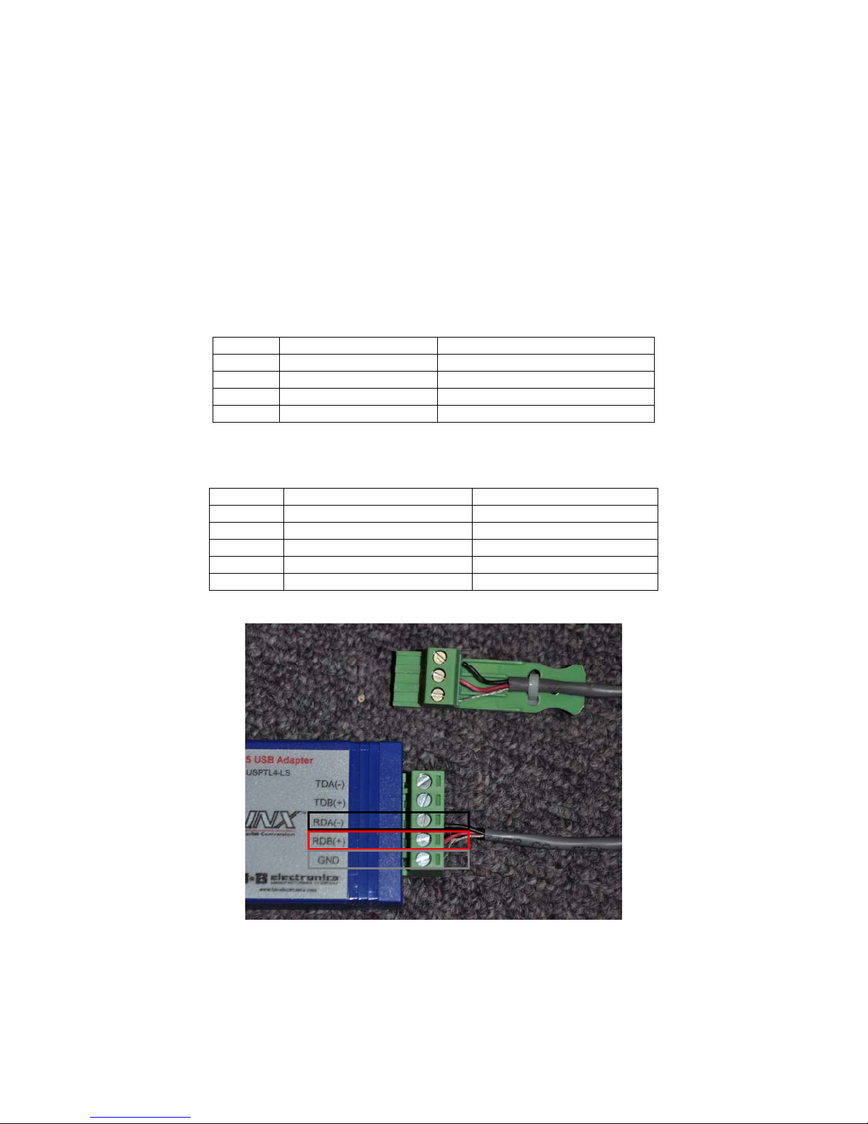
Wire the converter’s terminals as follows:
Terminal Connected To Purpose
TDA(-) Not Connected Unused
TDA(+) Not Connected Unused
RDA(-) DSA RS-485 Negative (-) Data A Input/Output
RDB(+) DSA RS-485 Positive (+) Data B Input/Output
GND DSA RS-485 Ground Ground
On the DSA, ensure that the “EIA-485 Terminate” switch is in the “On” position for the last DSA in
the RS-485 chain (farthest from the computer). If only one DSA is connected to the computer, this
switch should be in the “On” position.
Page 3 of 10
Page 4

ASG Tech Note: Connecting and Communicating with DSA
Within DSA Pilot, select “Com Settings” under the “Tools” menu. Ensure that “Analog Audio/EIA485 control” is selected under “Type”, and the correct COM Port is selected under “Properties”.
Once you have done this, you are ready to proceed to step 5A.
NOTE: No other USB converters (including USB-to-232 converters with 232-485 adapters) should
be used to upgrade DSA firmware. Doing so can result in a firmware update failure. Supplemental
steps will then be required to restore functionality of the DSA.
4C: Troubleshooting:
What if I already tried to communicate and upgrade firmware with a USB – 232
adapter? USB – 232 adaptors are not stable enough for the type of data transfer needed
for a firmware upgrade. When the DSA Pilot software for DSA is upgrading firmware, it
performs a system of checks and balances whereby the software erases one part of the
existing firmware, uploads the new firmware information, verifies a successful upgrade,
and moves to the next part of the upgrade. Because of the unstable transfer rate of the
USB – 232 converter, DSA and DSA Pilot Software may hang while trying to upgrade and
verify, resulting in a loop. At this point in the upgrade, most users choose to “force quit”
the process, or physically unplug the connection to DSA; possibly causing the LED on the
front may start to blink constantly.
This hard quit/disconnection causes the DSA to completely lose all firmware. You must
now “Force New Firmware” to restore functionality.
How do I perform a “Force New Firmware”?
To perform a “Force New Firmware” you must follow the steps below:
Step 1: Get the proper 232 serial connection from your computer. See Section 3 above.
Step 2: Reconnect to DSA.
Step 3: Go online (see Section 6 below) – this should call up the DSA module you were
upgrading firmware.
Step 4: Right click on that DSA module in the ‘Unassigned Modules’ section and select
‘Upgrade Firmware’
Step 5: In the window that opens, you will see the detected firmware version, the
available firmware version (current version is always the last one on the list – it is also
listed in the ‘Diagnostic’ window), and a box to ‘Retain Settings’. Uncheck the ‘Retain
Settings’ box.
Step 6: Click the ‘Update to Firmware Version’ button. This will force new firmware onto
DSA.
Step 7: Let DSA Pilot work to force new firmware. T his process should take no more
than 15-20 minutes. If it is taking longer than 20 minutes, you have an improper
connection. Confirm your connections via Section 3 above.
Step 8: When the firmware update is complete, verify that you are at the current firmware
by right clicking on the DSA module, and then clicking on ‘ Diagnostics’. This will show
you the detected version of firmware.
Page 4 of 10
Page 5

ASG Tech Note: Connecting and Communicating with DSA
Step 9: While still in the diagnostic window, click on the ‘Set to Defaults’ button to bring
the DSA module back to factory default settings.
Step 10: After setting back to factory default, click on the ‘Warm Reboot’ button to reboot
the DSA module.
At this point, the DSA module should be reset to factory default with the latest firmware.
5. Communicating with DSA
5A. Go ‘Online’
Once you have the proper connection to the DSA module, launch DSA Pilot and click the
‘Online’ button. This will poll your network and find the unassigned DSA modules. These
will appear in the ‘Unassigned Modules’ section of DSA Pilot. Individual DSA
loudspeakers will be referred to as ‘Modules’ when not assigned to a cluster.
Clicking on an individual DSA module will light up its respective LED on the front. It is
here you can right click on the individual DSA module and run diagnostics, as well as
rename the individual DSA module and upgrade firmware.
5B. Adding DSA Cluster(s).
Click ‘ADD CLUSTER’. This will add an ‘Unnamed Cluster’ in the “Clusters” window in
DSA Pilot and engage the drop down menu for choosing your cluster type, as well as
bring up a picture of what that cluster type looks like. Using the drop down menu, choose
the cluster type you will be working with.
Page 5 of 10
Page 6

ASG Tech Note: Connecting and Communicating with DSA
Note: All currently available clusters are in this drop down menu. This menu supersedes
the printed DSA Manual.
Note the position of LED’s in the pictures of clusters. This is helpful in making sure that the DSA
modules within the cluster(s) you install on the wall are in fact in the correct orientation.
As you can see from the diagram below, the 1A, 1B and 1C clusters are made up of single
enclosures only. A 1A cluster is a DSA250, “HF down”, and a 1B cluster is a DSA250, “HF up”.
The LED you will see is opposite where the HF section is located. A 1C cluster is a single
DSA230, LED at the bottom (shown above). There is no cluster for a DSA230 with the LED at the
top.
Page 6 of 10
Page 7

ASG Tech Note: Connecting and Communicating with DSA
5C. Assign Your DSA Modules to Their Respective Clusters.
Once you have added the cluster you will be working on, you will need to assign
individual DSA modules to its respective cluster. This is done by left clicking the individual
DSA module so it grays out, clicking the ‘ASSIGN’ button (the button will light up, a stylus
will now appear where your cursor/arrow was), then left clicking on the respective DSA
module under the cluster you wish to assign that module to.
For example, if you were using a 1C cluster (single DSA230, LED at bottom), you would
left click on the DSA230 in the ‘Unassigned Module’ window so it grays out, click on the
‘ASSIGN’ button, then left click on the DSA230 shown under the Unnamed Cluster, which
is your 1C cluster.
When you assign a DSA module for the first time, from a new DSA Pilot window, you
should be able to connect immediately. However, if there is a mismatch – if the DSA
module has information in it – you will get a window prompt asking you what you want to
do:
Page 7 of 10
Page 8

ASG Tech Note: Connecting and Communicating with DSA
WRITE SETTINGS TO THE LOUDSPEAKER: If you want to start clean and reset your
DSA module to factory settings, click this.
READ SETTINGS FROM THE LOUDSPEAKER: If you are connecting to an existing
installed DSA module, need to see how a DSA is set up, or any application where you do
not wish to erase the steering and EQ settings of your DSA, click this.
ABORT. DON’T CONNECT. If you are unsure about your connection, or you do not wish
to connect with that individual DSA loudspeaker, click this.
Once you click on your choice, the DSA in the ‘Unassigned Modules’ section will go
away, and you will get a green check next to where that module is assigned within the
cluster. Once all modules are assigned to a cluster, the cluster will also get a green check
next to it.
Page 8 of 10
Page 9

ASG Tech Note: Connecting and Communicating with DSA
Left clicking once on the cluster name will light up the LED’s for entire cluster (all
modules). Left clicking on the individual DSA modules within that cluster will light up the
individual LED’s on those DSA modules. This is helpful in making sure the correct DSA
modules are assigned properly, and that the orientation of the DSA modules is correct.
6. EQ and Steer the DSA Cluster(s).
Once connected, you can EQ and Steer your DSA cluster. It is important to realize that individual
DSA modules are never steered or EQ’d – only clusters are steered and EQ’d. You can get to the
steering and EQ windows either through the “Tools” drop down menu, or by right-clicking once on
the cluster you wish to steer or EQ.
In the EQ section, you should start off with your input gain at –10dB (default for firmware version
58 and higher). This may be increased or decreased as needed depending on the system’s gainstaging.
In the steering section, you want to switch from ‘Specify Coverage Pattern’ (which is default) to
‘Match Coverage to Listening Area’.
DSA is a loudspeaker system – processing, amplifiers, and loudspeakers. In a DSA250, there are
sixteen drivers, sixteen channels of DSP, sixteen channels of amplification. There is the
possibility of some amp noise commonly referred to as “hiss” if the DSA loudspeaker is not
properly gain staged with the rest of the system, especially if the signal feeding DSA is low, and
the input gain on DSA is being used to compensate.
Page 9 of 10
Page 10

ASG Tech Note: Connecting and Communicating with DSA
Placement of DSA is also a consideration. Unlike traditional column loudspeakers (which DSA
physically resembles), DSA is not limited to low physical positioning (anything under 10’), and we
have found that performance generally improved with mounting heights over 10’. The reason
traditional column loudspeakers need to be low is due to their inherent narrow vertical dispersion,
centered on the vertical axis of the loudspeaker. The low positioning allows those traditional
loudspeakers to ‘skim’ the heads of the listening audience, such that the most distant seats are
on-axis, with nearer seats becoming progressively more off-axis as you approach the column.
This limitation does not apply to DSA, which can form complex beams that are not centered on
the vertical axis of the loudspeaker.
If you have any further questions on connection or operation of the DSA, call the
EAW ASG Group at 1-800-992-5013 BEFORE you connect to the DSA.
January 2013. EAW Application Support Group.
Page 10 of 10
 Loading...