

Page 1
EAW’s CSC Series
Screen Channel Systems
A Technical Overview
Page 2
System Overview
The CSC Series three-way screen channel loudspeaker systems from EAW address many issues raised
by the changing design trends of modern cinemas. The features and benefits of this product design are
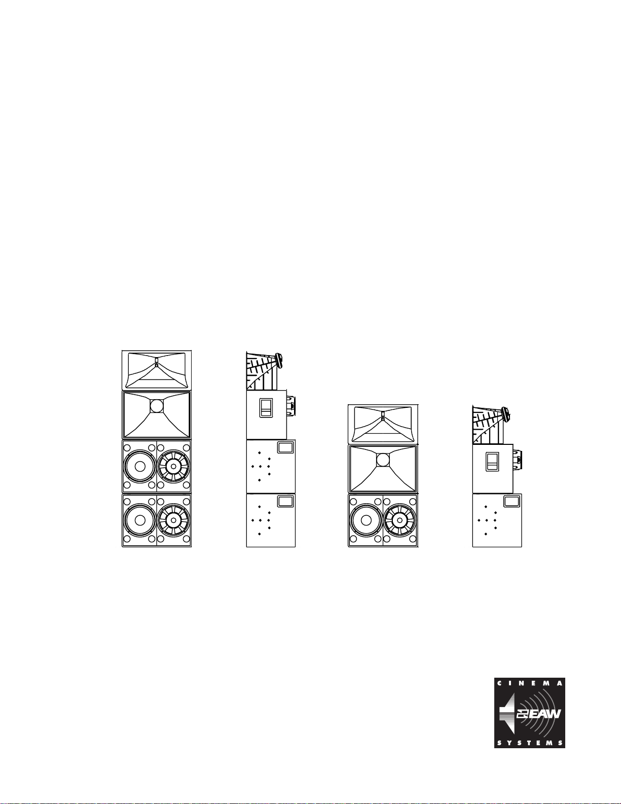
manifested in two models at the present time: the CSC923 (and its biamplified version, CSC923X), and the
CSC723 (and its biamplified version, CSC723X).
The CSC923 is intended for screen channel use in very large cinemas exceeding 90 feet (27.4 meters)
in length from screen to last row. The CSC723 is intended for screen channel use in cinemas up to 90 feet (27.4
meters) in length from screen to last row.
The challenge of coverage in steeply-raked seating areas
The primary design feature of the CSC Series is its remarkable asymmetrical mid and high frequency
horn designs. While the predominant theatre design of new construction sites includes “stadium style”
seating plans, loudspeaker manufacturers have only begun to actually adapt speaker designs which attempt
to address this room geometry. Although the concept of asymmetrical pattern horns has been in existence for
some time, it has only recently surfaced as a viable approach for the specific requirements of cinema sound.
The application of this horn design for cinema makes particular sense because we have a known “standard”
room dimension proportion (length x width); the most significant variable is scale and floor slope. But, as
any loudspeaker designer knows, any change
to room geometry changes the coverage you
can expect from a given horn design.
Conventional 90º x 40º constant
directivity horns do a good job of providing
even coverage for traditional moderate-slope
cinemas. The trade-off of on-axis positioning
against seating in or out of the horn’s defined
coverage pattern results in a fairly even SPL
throughout most seating areas.
Once the floor slope is increased, this
trade-off becomes off-balance; now the closest
seats in front are brought into the coverage
pattern. Attempting to aim the horn for even
coverage results in making a new trade-off
between providing good HF to either the
farthest rows or the nearest rows. If the conventional horn is aimed to reach the last rows, HF coverage in the
front rows will suffer, and vice versa. Another issue is the energy directed toward the ceiling, now that the
conventional horn is aimed upward for the back rows. This is not only wasted energy, but also potentially
reflects energy from the ceiling back into the seating area, which could interfere with dialogue intelligibility.
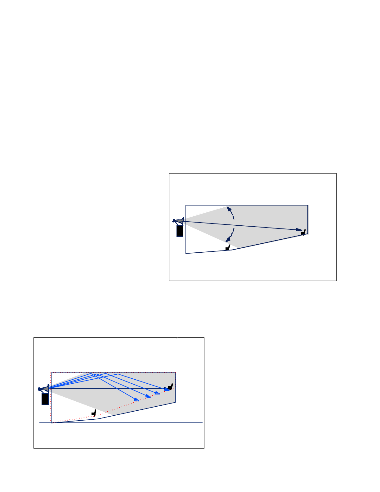
A horn designed to provide an asymmetrical coverage pattern will produce a pattern which projects
energy directly on-axis and downward, instead of equal angles above and below its center axis. Thus much
40 degrees vertical
of its energy reaches the back rows, while
the seating area in front is also still well
within the horn’s defined coverage pattern.
Both the HF and MF horns in the
CSC Series feature an asymmetrical shape
which produces a coverage pattern which
can be described as 80 to 90 degrees horizontally by 50 degrees vertically. The range
(80-90 degrees) of the horizontal pattern
produces even coverage on the seating area
because, to the horn, the seating area
appears trapezoidally-shaped. This helps
minimize energy directed to the walls of the
theatre, and focuses coverage to the audience.
page 2
Page 3

Since the vertical coverage pattern tilts
downward, we recommend little or no downward horn aiming. Instead the system is aimed
by elevation; the HF horn should be elevated to
a height where it is directly in line with the last
row of seats. This has been found to provide the
best coverage front to back, and significantly
simplifies setup and installation by removing
the “guesswork” traditionally associated with
horn-aiming behind the screen.
Screen compensating HF horn design
Another feature of the HF and MF horn design of the CSC Series addresses the so-called “screen
effect” of the perforation of standard perf screens. Several phenomena contribute to create a dispersion
“widening effect”. First, sound that is reflected off the rear of the screen, back into the mouth of the horn is
then passed through the screen at random angles. Also, when short wavelength frequencies pass through the
perfs, the holes themselves tend to widen dispersion, increasing with frequency beginning at frequencies
above about 5 kHz. The higher the frequency, the wider the pattern effectively becomes. However, it has
long been known the most high frequency devices tend to naturally narrow in dispersion. This “beaming
effect” has traditionally created a challenge for horn designers trying to achieve even coverage. During R&D
efforts for the CSC Series, the beaming effects of the HF driver and the widening effects created by the cinema
screen were measured with great precision by EAW engineers. As a result, the HF horn in the CSC Series
addresses this phenomenon by subtle shaping of the critical throat section of the horn,
which allows the horn to "beam" at a frequency where the effect of the screen will broaden
the coverage. The result is a more controlled high frequency dispersion pattern after the
screen.
Push-Pull LF Driver Configuration
The LF section of the CSC Series uses “push-pull” driver mounting which significantly lowers mechanically induced distortion. Any driver will produce a certain degree
of distortion simply as a result of the motor action of the piston (voice coil/cone assembly).
When the array includes pair of identical drivers, simply inverting the mounting orientation of one driver will cause the mechanical distortion produced by one driver to “cancel”
the same distortion produced by the other. With the CSC Series, each push-pull driver pair
is loaded into its own modular enclosure, to make moving and installing the speaker easier
and less cumbersome.
EAW’s VA4 Technology
In addition to optimized coverage, the CSC Series also features proprietary EAW design technology
which significantly improves dialogue clarity. VA4 Technology is a breakthrough EAW design philosophy
which has been used successfully in several popular EAW professional sound systems. The main focus of
VA4 design is how it addresses time alignment in the critical mid-band frequencies. The CSC Series’ patented
phase plug design solves problems of early arrivals in the upper mid frequency range by developing a more
logical cone geometry.
With this design, all paths from the source (voice coil) through the cone assembly (cone, dustcap and
surround) and into the horn throat are virtually identical. This subtle yet important breakthrough gives the
CSC Series its remarkably clear sound.
Cinema screen channel loudspeaker systems strive to optimize performance in four areas:
• spectral (frequency range, sound quality)
• spatial (pattern control, SPL distribution)
• temporal (unified arrivals from various subsystems)
• utilitarian (size and weight, ease of installation)
page 3
Page 4

Unfortunately, optimization in one area usually results in trade-offs elsewhere. For example, spatial
performance (pattern control) can be optimized by very large horns, but the resulting enclosure’s utility will
be severely degraded.
The goal of the CSC Series was to optimize performance attributes in all areas without compromising
others. Specifically, the main goals were:
• unifying arrival times within and among the subsystems
• achieving broadband pattern control in the both the vertical and horizontal planes
• creating a modular system that’s easy to move, install, and aim
• setting a new standard in audio fidelity
Optimized Mid-Frequency Sub-System: Achieving temporal coherence and spatial consistency
EAW has historically created true three-way cinema loudspeaker systems that use cone transducers
to reproduce the majority of the vocal region. This approach significantly reduces distortion resulting in more
natural sounding dialogue. But the additional LF section has typically created compromises in the temporal
and spatial domains.
In addition to the sonic difficulties associated with transitioning between subsystems in the heart of
the vocal band, two-way systems suffer from higher distortion in the lower portion of the compression
driver’s range. In the temporal domain, however, two-way systems excel where typical three-way systems
falter.
Unlike the relatively simple geometry of a compression driver’s diaphragm, there is a slight but
noticeable difference in the point of origin of a cone driver’s dustcap, cone, and surround. Particularly in the
upper midrange, these differences create a “smearing” of arrival times at the listener that degrades the clarity
and impact of mid-frequency sonic events: most notably voice reproduction. Because they are what the ear
hears first, early arrivals out of the passband can affect overall fidelity even though they are substantially
lower in level.
Traditionally, most manufacturers (including EAW) have asked the mid-frequency phase plug to fix
the arrival smear. But because this approach treated the symptom (inconsistent arrivals at the horn throat)
instead of attacking the disease (bad cone geometry),
Traditional Mid Cone with Phase Plug, Side View Cutaway
Dustcap
Surround
Cone
Voice Coil
Traditional Phase Plug Creates Ring Radiator
Voice Coil to Surround = 6.3 inches
Voice Coil to Dustcap = 4.5 inches
Conventional phase plug designs achieve this result by using a circular entrance and exit to
the phase plug – they simply convert the output from a point source into a ring radiator. This approach has
proven effective with high frequency compression drivers mostly because the simpler compression driver
diaphragm geometry and shorter high frequency wavelengths create significantly smaller arrival differences
that are less problematic to resolve. But because the wavelengths in the mid frequency passband are so much
greater, this ring radiator solution actually creates another more serious problem.
A ring radiator exhibits a more dramatic narrowing of beamwidth with increasing frequency than a
cone transducer. When the mid frequency device becomes a ring radiator, its directivity narrows too greatly
with increasing frequency to the point where it no longer fills the bell of the horn. This is a problem that
virtually all horn-loaded mid or midbass systems suffer from, including systems that are highly regarded in
the professional audio and cinema sound communities. As a result all of these systems exhibit acceptable
low/mid coupling, but the mid/high energy does not cover from box to box, leaving upper mid holes in the
frequency response on the seams of an array.
The CSC Series mid/phase plug assembly approaches the problem in a different way. It attacks the
it fails. In contrast, the CSC Series’ entire mid frequency cone and phase plug assembly was designed
to solve this problem at the source.
The distance from a cone driver’s voice coil
to its dustcap is shorter than the distance from the
voice coil to either the cone or surround. Therefore,
the energy radiating from the dustcap most often
leads the energy from the rest of the system. Traditional phase plug designs have isolated this energy
and routed it through a longer path than that which
faces the energy from the cone or surround. In so
doing, the phase plug attempts to equalize the arrival
smear.
page 4
Page 5

problem at the source. The cone transducer’s temporal smear is corrected by precisely aligning the cone/
Traditional Mid Cone with Phase Plug, Side View Cutaway
VA4 Phase Plug uses Radial Slots to Maintain Source Directivity
dustcap/surround geometry to maintain temporal
unity. The distance to the dustcap is slightly longer to
Surround
Voice Coil
Dustcap
Radial Slots
Cone
compensate for differences in material density.
The phase plug, whose geometry is matched to
the cone, then serves to leave this unity intact. Expanding radial slots within a compressing frame lower the
mechanical reactance of the load facing the transducer
without modifying the directivity associated with the
source. This allows for faithful reproduction of the upper
mid-frequencies without any narrowing of beamwidth.
The wavelets (below) illustrate the difference
between old and new mid-frequency cone/phase plug
Voice Coil to Surround = 6.3 inches
Voice Coil to Dustcap = 6.8 inches
technologies. These wavelets represent data gathered at 1
meter from devices mounted in a pseudo-infinite baffle wall. The vertical axis indicates frequency, the horizontal indicates time, and color indicates dB SPL with each color change indicating a 1 dB drop in level. The
first illustration represents data obtained from a conventional midrange transducer. Particular attention
should be paid to the upper midrange above 1 kHz. Note that the energy at the top of the passband centered
around 2.1 kHz is
slightly leading the
rest of the broadband
energy and also
remains considerable
after.
This difference of
microseconds is
difficult to observe
without precision
measurements, but the
phenomenon is quite
audible. The resulting
reproduction would
take a finite sonic
event (a Foley door
slam, gunshot, or footstep, for example) and reproduce it over a longer period of time than it had actually
taken. The source has been compromised and the events’ clarity and impact degraded. With the harmonics
leading and/or lagging the fundamental tone, the timbral quality of the acoustic event is lost.
The next illustration results from an identical measurement taken on a new CSC mid-range transducer. Needless to say, the temporal inconsistencies have been eliminated through the implementation of a
more logical transducer geometry.
In the end, the mid-frequency sub-system of the CSC Series exhibits the temporal clarity of a com-
pression driver alone
(as in a two-way
system) and the
natural low distortion
sonic reproduction of a
cone transducer (as in
an EAW three-way
system) while removing crossover transitions from the vocal
region and maintaining the spatial performance required for
broad band constant
directivity.
page 5
Page 6

One Main Street, Whitinsville, MA USA 01588 • (508) 234-6158 • FAX (508) 234-8251 • Email info@eaw.com • Web http://www.eaw.com
EAW products are continually improved. All specifications are therefore subject to change without notice. • 5/30/00
 Loading...