

Instructions/Installing the KF850z
NL8 and AP6 Upgrade Kits
The KF850z AP6 Upgrade Kit P/N 0006241 and the KF850z NL8 Upgrade Kit P/N 0006242 are available for the
KF850e loudspeaker. These two kits are the same but for the Electrical Assemblies.
Warning: Installation should only be done by an experienced technician. Improper installation may result
in damage to the equipment, injury or death.
1. Inventory the kit against the following bill of materials insuring the kit is complete.
EAW P/N Qty Description
804116 1 Driver-Cone (LC-1536)
102021 4 Screw 1/4-20 X 1-1/2 LG SHCS Blk
0005848 1 Horn/URE/H4532
0008726 1 Driver/Compression [DN20/3004-8]
102165 4 Screw/M6 X 14mm LG HHCS
105005 4 Washer/Flat 1/4
105004 8 Washer/Lock 1/4
0006004 2 Bracket/Horn [KF850z Upgrade Kit]
102016 6 Screw 1/4-20 X 1 LG PH PHMS Blk
105007 10 Washer/Flat 1/4 Blk
105008 10 Washer/Lock 1/4 Blk
102017 4 Screw 1/4-20 X1 SHCS Blk
804097 1 Driver-Cone [LC-1075]
0006008 1 Assembly/Phase Plug/Housing
0006005 1 Ring/Aperture/Wood/10” Mid [KF850z]
0006007 4 Screw 1/4-20 X 4-1/2 LG SHCS Blk
105033 4 Washer/Flat/M6
0006011 1 Instruction/Kit/KF850z/Upgrade
102087 4 Screw #8 X 1 LG PH PHSMS
102048 8 Screw #10 X 16 X 3/4 PH PHSMS
102102 23 Screw #8 X 5/8 PH PHSMS Blk
0006239 1 Electrical Assembly KF850z [NL8]
or
0006240 1 Electrical Assembly KF850z [AP6]
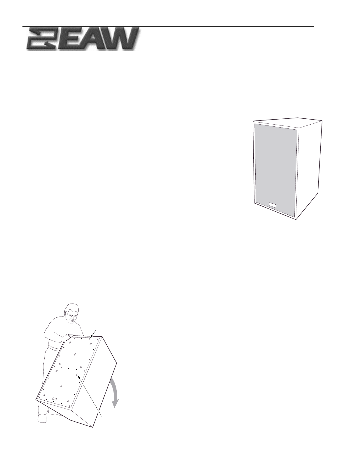
2. Overview
KF850z Kit installation requires the technician to remove and replace all transducer components. The HF
horn assembly is accessed from the front and the 15” woofer, 10” mid range, and electrical assembly from
the back.
To do this the enclosure will first be rested on its back, the grille
removed, and the HF horn assembly disconnected, removed, and disassembled. Its rear bracket will be re-installed into the new KF850z
HF horn assembly, which will then be installed into the enclosure.
After this is complete the enclosure should be repositioned onto its
front, and the 2 access lids, polyfill, input and crossover removed, the
new crossover installed, and its leads routed to the appropriate chambers. Then the new 15” woofer and the new mid assembly will be
installed. The old polyfill should be restapled into both chambers and
the new electrical assembly installed.
Finally the enclosure will be stood upright, HF leads connected, tested for continuity, and access lids and grille reinstalled.
3. Instructions: Tip the enclosure on its back and remove the 23
Phillips head screws that mount the grille to the enclosure.
S
REMOVE AND DISCARD
23 #8 X 5/8 LG PHILLIPS
HEAD SHEET METAL SCREW
10X GRILL
FOAM RETAINERS
(DO NOT REMOVE)
T
Y
6
)
)
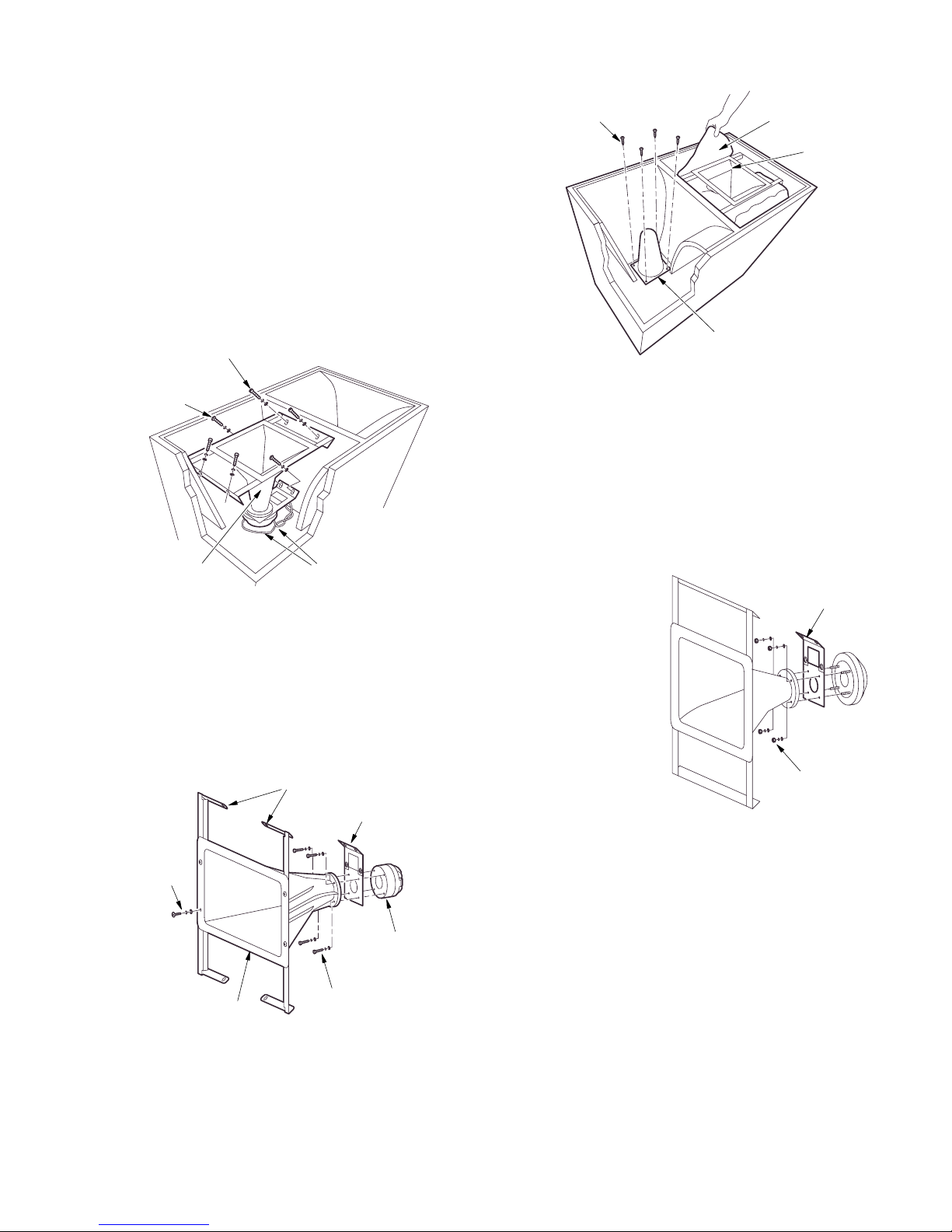
5. Removing the High Frequency Assembly
a. Disconnect the two leads.
b. Remove and discard the 2 Phillips head screws, lock
and flat washers that hold the back bracket to the enclosure.
c. Remove and discard the 4 socket head cap screws, lock
and flat washers that attach the front metal bracket to
the enclosure.
d. Lift the HF assembly from the enclosure.
4. Removing the Pillow and Wave Guide
The pillow is beneath the HF horn assembly and held to
the side walls of the enclosure by hook-and-loop tape.
Tug the sides of the pillow free and lift it out.
The waveguide/grille is attached by 4 Phillips head screws.
Remove the screws and remove the waveguide.
The pillow and waveguide will not be reused.
6. Dissassembling the High Frequency Assembly
a. Remove the 4 M6 nuts, lock and flat washers.
b. Separate the driver from the horn and remove the rear bracket. DO NOT
remove the 2 Phillips head screws that hold the two halves of the rear
bracket together.
c. The HF assembly may be discarded except for the rear bracket.
7. Building up the new the High Frequency Assembly
a. Assemble the driver and rear bracket to the round horn
flange using the 4 M6 bolts, lock and flat washers.
b. Attach the 2 brackets to the front horn flange as shown
using 4 black 1/4-20 x 1 lg Phillips head screws, 4 black
lock washers and 4 black flat washers.
8. Attaching the new the High Frequency Assembly to the Enclosure
a. Place the new HF assembly into the enclosure aligning the 4 slots in the front bracket and the 2 slots in the rear
bracket with the threaded holes in the HF chamber. Attach the front bracket to the enclosure with 4 black 1/4-20
x 1 lg socket head cap screws, lock and flat washers. Use 2 black 1/4-20 x 1 lg Phillips head screws, lock and flat
washers to attach the rear bracket to the enclosure. The 2 elecrical leads are attached in Step 12b.
4X PHILLIPS HEAD SCREWS
(REMOVE AND DISCARD)
PILLOW (REMOVE AND DISCARD
HIGH FREQUENCY
HORN ASSEMBLY
4X SOCKET HEAD CAP SCREWS
LOCK AND FLAT WASHERS
(REMOVE & DISCARD)
2X PHILLIPS HEAD
SCREWS LOCK
AND FLAT WASHERS
(REMOVE AND
DISCARD)
DISCONNECT
HIGH FREQUENCY
HORN ASSEMBLY
RED AND BLACK
WIRE ELECTRICAL LEADS
4X NEW 1/4-20
X 1" LG BLACK
SOCKET HEAD
CAP SCREWS,
LOCK AND
FLAT WASHERS
2X NEW HORN BRACKET
P/N 0006004
REUSED REAR BRACKE
NEW H4532
HORN P/N 0005848
NEW HIGH FREQUENC
DRIVER P/N 000872
4X NEW 6mm HEX HEAD
SCREWS, LOCKWASHER & FLAT
WASHER (USING 10mm WRENCH
WAVE GUIDE (REMOVE AND DISCARD)
REAR BRACKET
REMOVE NUTS, LOCK
WASHER & FLAT WASHER
USING 10mm WRENCH

9. Reposition the Enclosure on its face.
With the grille still removed,
a. Reposition the enclosure front down.
b. Remove the 18 hex head screws and flat
washers that attach the two lids.
c. Lift the the two lids from the enclosure.
Retain the hardware and lids.
d. Remove all the polyfill fiber that surounds
the 10” and 15” drivers. Retain the polyfill.
e. Disconnect the 2 electrical leads from both
drivers.
f. Remove the 8 socket head screws that hold
both drivers into the enclosure and lift the
drivers away. Do not retain hardware or
drivers.
g. Remove and discard the 8 input Phillips
head mounting screws and dangle the input to the side of the enclosure as shown.
h. Free the electrical leads that pass thru partitions inside the enclosure.
i. Remove and discard the 4 crossover mounting screws and lift the electrical assembly from the enclosure.
S
)
10. Installing the new Electrical Assembly
a. Attach the new crossover as shown
with the 4 supplied #8 x 1” long
Phillips head screws.
b. Insert the blue and black leads from
the input board thru the partition
into the 15” woofer chamber.
c. Insert the red and black leads from
the crossover board, thru the partition, down thru the rectangular hole
into the HF chamber.
d. Seal the hole in the partition with
user supplied putty or silicone.
11. Installing the new Mid Driver and Woofer
a. Place the wooden aperture and new phase
plug into the mid chamber.
b. Position the new 10” driver onto the phase
plug.
c. Insert the 4 supplied 4-1/2 lg screws, lock
washers and M6 flat washers thru the
driver, phase plug and aperture into the
threaded holes in the baffle and tighten.
d. Install the input with the 8 supplied #10
Phillips head screws.
e. Connect the yellow and black leads from
the input board to the 10” mid driver. The
black lead to the black terminal.
f. Attach the new 15” woofer using 4 supplied
1/4-20 x 1-1/2 long screws.
g. Connect the blue and black leads from
the input board to the 15” woofer. The black
lead to the black terminal.
h. Restaple the polyfill into both chambers.
8X 1/4-20 X 1 HEX HEAD CAP
SCREWS & FLAT WASHERS
(DO NOT DISCARD HARDWARE)
SMALL LID
4X 1/4-20 X 1 LG
SOCKET HEAD
CAP SCREWS
(DISCARD
HARDWARE)
10 INCH MID DRIVER
(YELLOW AND BLACK
LEADS DISCONNECTED)
10X 1/4-20 X 1 HEX HEAD CAP
SCREWS & FLAT WASHERS
(DO NOT DISCARD HARDWARE)
LARGE LID
4X 1/4-20 X 1 LG SOCKET
HEAD CAP SCREW
(DISCARD HARDWARE
LEADS DISCONNECTED)
15 INCH WOOFER
(BLUE AND BLACK
REMOVED INPUT
(EIGHT #8 X PHILLIPS HEAD
SCREWS NOT SHOWN DISCARD HARDWARE)
RED AND BLACK LEADS FROM
CROSSOVER THRU PARTITION
& THRU RECTANGULAR CUTOUT
TO HIGH FREQUENCY ASSEMBLY
ELECTRICAL ASS'Y
INCLUDES THE
CROSSOVER BOARD
AND INPUT
(AP6 OR NL8)
BLUE AND BLACK LEADS FROM
INPUT THRU PARTITION
TO 15 INCH WOOFER
YELLOW AND BLACK
TO 10 INCH MID DRIVER
4X #8 X 1 LG PHILLIPS
LEADS FROM INPUT
4X 1/4-20 X 1-1/2 LG SOCKET
HEAD CAP SCREWS
BLK P/N 102021
NEW 15 INCH
WOOFER P/N 804016
(CONNECT BLUE
AND BLACK LEADS )
NEW INPUT HARD WIRED
TO INSTALLED CROSS OVER
HEAD SCREWS
INPUT OPENING MAY BE USED
TO ACCESS 10 INCH WOOFER
MOUNTING SCREWS
4X 1/4-20 X 4-1/2 LG
SOCKET HEAD
CAP SCREWS,
LOCK WASHERS
& M6 FLAT
WASHERS
NEW 10 INCH MID
DRIVER P/N 804097
PHASE PLUG ASS'Y
P/N 0006008
WOODEN APERTURE
RING P/N 0006005

If you have questions about the KF850z kit installation please contact the EAW Application Support Group:
Tel 800-992-5013 (USA only)
Tel 508-234-6158
Fax 508-234-8251
E-mail asg@eaw.com
Thank you for purchasing
EAW products
One Main Street, Whitinsville, MA 01588 tel 800 992 5013 / 508 234 6158 fax 508 234 8251 web www.eaw.com
The Laws of Physics | The Art of Listening
EAW is the worldwide technological and market leader in the design and manufacture of high-performance, professional loudspeaker systems.
EAW P/N 0006011 (A) 6NOV03
12. Finishing the Kit Installation
a. Stand the enclosure upright.
b. Connect the red and black leads to the high frequency driver. The black lead to the black terminal.
c. Continuity check the low frequency, mid and high frequency drivers.
g. Re-attach the two access lids.
h. Re-attach the grille.
ATTACH RED AND BLACK LEADS
FROM NEW CROSSOVER BOARD
RE-ATTACH BOTH ACCESS
LIDS WITH THE 18 OLD
1/4-20 X 1 LG HEX HEAD
CAP SCREWS AND
FLAT WASHERS
RE-ATTACH GRILLE AND GRILLE FOAM
WITH THE 23 SUPPLIED #8 X 5/8 LG
PHILLIPS HEAD SHEET METAL SCREWS
 Loading...