

Page 1
SPECIFICATIONS AS690e
DESCRIPTION
APPLICATION
PERFORMANCE
One Main Street, Whitinsville, MA 01588 508 234 6158 Toll Free 800 992 5013 FAX 508 234 8251 [email protected] www.eaw.com
EAW products are continually improved. All specifications are therefore subject to change without notice. AS690e/2 pp October 2001 Printed in USA
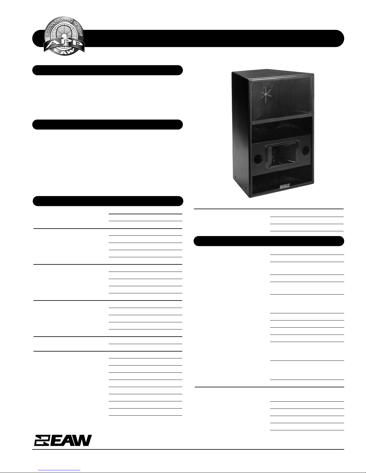
A bi-amplified (passive mid/high crossover) or tri-amplified
3-way full range system in a trapezoidal enclosure. Includes
2x 12-in woofers (separated vertically), a horn-loaded 10-in
MF cone with Radial Phase Plug™ and a 1.4-in exit/2.5-in
voice coil HF neodymium compression driver on a 90° x 45°
constant directivity horn.
The AS690e is engineered for use in permanent installations.
Optimized subsections provide excellent full range frequency
response in a medium format enclosure. Includes comprehensive 3/8"-16 mounting/suspension points. Six year warranty.
Applications include:
Stadiums Arenas
Performing Arts Centers Houses of Worship
Frequency Response (Hz)
±3 dB 67 Hz to 15 kHz
-10 dB 50 Hz
Axial Sensitivity (dB SPL, 1 Watt @ 1m)
Passive MF/HF 107
LF 102
MF 109
HF 109
Impedance (Ohms)
Passive MF/HF 8
LF 4
MF 8
HF 8
Power Handling (Watts, Continuous)
Passive MF/HF 450
LF 800
MF 400
HF 125
Recommended High-Pass Frequency
24 dB/Octave 40 Hz
Calculated Maximum Output (dB SPL @ 1m)
Passive MF/HF Peak 139
LF Peak 137
MF Peak 141
HF Peak 136
Passive MF/HF Long term 133
LF Long Term 131
MF Long term 135
HF Long Term 130
Nominal Coverage Angle/-6 dB points (degrees)
Horizontal 90
Vertical 45
Product Group I
System Configuration 3-way, full range
Powering Configuration(s) Bi-amplified (passive MF/HF
crossover) or tri-amplified
LF Subsystem & Loading 2x 12-in, vented
MF Subsystem & Loading 1x 10-in cone, Radial Phase
Plug™/ horn-loaded
HF Subsystem & Loading 1x 1.4-in exit/2.5-in voice coil
neodymium compression driver
on constant directivity horn
Cabinet Type (shape) Trapezoidal
Enclosure Materials Exterior grade Baltic birch
plywood
Finish Wear-resistant textured black paint
Connectors 2x 6-Contact terminal barrier
strip, jumpers used for powering
configuration
Suspension Hardware (18) 3/8"-16 threaded mounting/
suspension points (4 each on top,
bottom and sides, 2 on back)
Grille Powder coated perforated steel
Dimensions inches millimeters
Height 36.0 914
Width (Front) 24.6 626
Width (Rear) 12.3 312
Depth 23.0 584
Trapezoid Angle 15 degrees per side
PHYSICAL
Page 2
SPECIFICATIONS AS690e
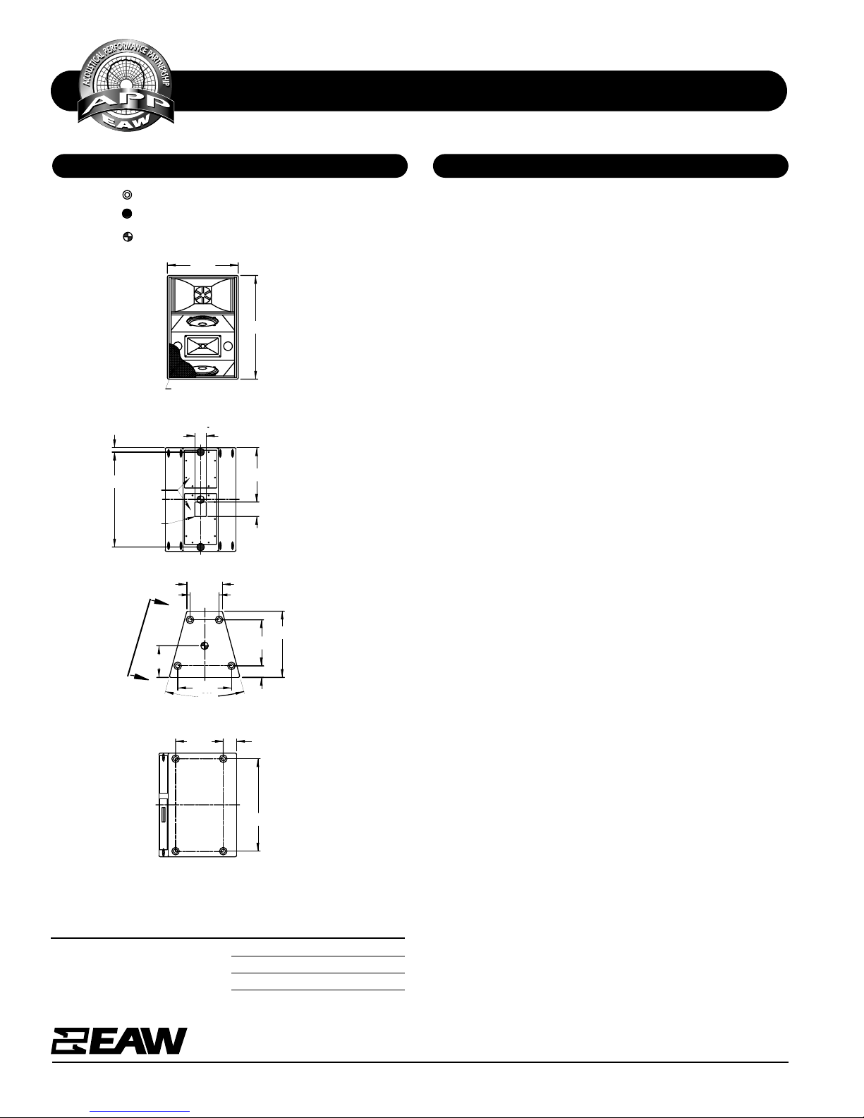
DIMENSIONAL DRAWING
A & E SPECIFICATIONS
One Main Street, Whitinsville, MA 01588 508 234 6158 Toll Free 800 992 5013 FAX 508 234 8251 [email protected] www.eaw.com
EAW products are continually improved. All specifications are therefore subject to change without notice. AS690e/2 pp October 2001 Printed in USA
Weights pounds kilograms
Net Weight 169 76.0
Shipping Weight 184 83.7
INDICATES MOUNTING POINT, 3/8-16 THREADED HOLE
(PI ANGLE).
INDICATES MOUNTING POINT, 3/8-16 THREADED HOLE
(NUT PLATE).
SYMBOL INDICATES CENTER OF BALANCE
FRONT
36.00
24.63
GRILLE PARTIALLY SHOWN
BACK
C
L
5.00
L
C
INPUT
PANELS
ACCESS
33.00
18.88
4.00
(1.50)
TOP/BOTTOM
133 (0)
5/10/01
4.00
A
A
C
L
11.00
23.00
16.00
18.67
(12.29)
10.09
30°
509133 (0)
5/10/01
30°
The bi-amplified or tri-amplified 3-way full range loudspeaker
system shall incorporate 2x 12-in LF vented transducers, a
horn-loaded 10-in MF cone with Radial Phase Plug™ and a
1.4-in exit/2.5-in voice coil HF neod ymium compr essi on d river.
The LF drivers shall be mounted in slanted baffles and sepa-
rated vertically. The MF d river shall be loaded into a midrange
horn constructed of 1/8-in birch plywood backed with high
density polyurethane foam. The HF driver shall be loaded on
a constant directivity horn with a nominal coverage pattern
of 90° (h) x 45° (v). An internal passive filter network shall
provide fourth order acoustical crossover and system equalization between the MF and HF subsystems.
System frequency response shall vary no more than ±3 dB
from 67 Hz to 15 kHz measured on axis . Th e mid/high section
shall produce a Sound Pressure Level (SPL) of 107 dB SPL on
axis at 1 meter with a power input of 1 Watt, and shall be
capable of producing a peak output of 139 dB SPL on axis at
1 meter. The low frequency section shall produce a Sound
Pressure Level (SPL) of 102 dB SPL on axis at 1 meter with a
power input of 1 Watt, and shall be capable of producing a
peak output of 137 dB SPL on axis at 1 meter. The mid frequency section shall produce a Sound Pressure Level (SPL) of
109 dB SPL on axis at 1 meter with a power input of 1 Watt,
and shall be capable of prod ucing a peak output o f 141 dB SPL
on axis at 1 meter. The high frequency section shall produce
a Sound Pressure Level (SPL) o f 109 dB SPL on axis at 1 m eter
with a power input of 1 Watt, and shall be capable of producing a peak output of 136 dB SPL on axis at 1 meter. The
mid/high section shall handle 450 Watts of amplifier power
(continuous) and shall have a nominal impedance of 8 Ohms.
The low frequency section shall handle 800 Watts of amplifier power (continuous) an d shall have a nominal impedance of
4 Ohms. The mid frequency section shall han dle 400 Watts of
amplifier power (continuous) and shall have a nominal
impedance of 8 Ohms. The high frequency section shall handle 125 Watts of amplifier power (continuous) and shall have
a nominal impedance of 8 Ohms.
The loudspeaker enclosure shall be trapezoidal in shape. It
shall be constructed of multi-ply, void-free, cross-grain-laminated, exterior grade, Baltic birch plywood and shall employ
extensive internal bracing. It shall be finished in wear-resistant textured black paint. Input connectors shall be 2x 6Contact terminal barrier strips, jumpers used for powering
configuration. Ei gh teen (18) 3/8"-16 thread ed m oun tin g/suspension points (4 each on top, bottom and sides, 2 on back)
shall be provided. The front of the loudspeaker shall be covered with a powder coated perforated steel grille.
The bi-amplified or tri-amplified 3-way full range loudspeaker
shall be the EAW model AS690e.
SIDE VIEW (VIEW A-A)
DIMENSIONS APPLY TO BOTH SIDES
Manufacturing tolerances are +/- 0.13 and +/- 1°
16.56
4.63
C
L
32.10
 Loading...