

Page 1

Electro-hydraulic Fan Drive System
Efficient cooling power,
where you need it.
Page 2

Complete
Fan Drive
Systems
The Electro-hydraulic (EH) Fan Drive System cools
your engine and vehicle sub-systems by controlling
a hydraulic pump and motor with a digitally
programmable controller.
The EH Fan Drive System equipped with the Two
Channel Amplifier offers fast, quiet and efficient
cooling for engine coolant, hydraulic fluid, charge air
and entire engine compartment.
Electro-hydraulic Fan Drive
benefits include:
• Flexible installation for
optimum fan location
• Elimination of belt
maintenance
• More accurate control
of charge air temperature
can help reduce engine
emissions
• Improvement in fuel
economy
• Increased power output
• Choice of variable- or xed-
displacement systems
Eaton can be your
single source for fan drive
systems.
Eaton Fan Drive Systems
can include:
• Pump (xed- or variable-
displacement)
• Motor
• Valves & manifold
• Electronic controls
• Compact patented
reservoir
• Filter
• Hoses and ttings
A fully integrated
electronically controlled
Eaton Hydraulic Fan Drive
System delivers a comprehensive cooling solution with
complete controllability.
Table of
Contents
Applications and Benefits 3
Electronic Controller Options 4
Integrated Fan Drive System, Fixed-displacement Pump 6
Stand-Alone Fan Drive System, Variable-displacement Pump 7
Fan Drive System Pump and Motor Guide 8
Hydraulic Components 9
Engineered Systems 10
Information contained in this document is subject to change without notice. Performance values are typical values. Customers are responsible for selecting products for
their applications using normal engineering methods.
Page 3

Applications
and Benefits
Applications:
On-highway vehicles
• Buses
• Recreational vehicles
Construction machinery
• Excavators
• Loaders
• Cranes
• Forklifts
Agriculture machinery
• Tractors
• Forest machinery
Benefits of
Electronic Control
• Functions with Engine Control Module Input or Vehicle
Sensor and Switch Inputs:
– Allows a wide variety of
congurations.
• Communications via RS
323 or CANbus link:
– Provides versatility in
communications.
• Conditions engine control
module signal:
– Filters noise, inverts sig-
nal, and re-scales signal
to optimize control.
• Uses closed-loop current
control, instead of voltage
control:
– Improves control
accuracy of fan speed by
eliminating temperature
effects on proportional
valve coil.
application SpEcific BEnEfitS
Buses
• Modulates fan speed
– Reduces operating power
and noise.
• Limits fan speed on start-up
– Reduces fan power draw
on start-up.
• Increased fuel economy
– Reduced fan power re-
quirements lead to better
fuel economy.
Recreational Vehicles
• Ramps between fan speed
settings
– Ensures gentle speed
transitions and provides
smooth operation.
• Reduces operation noise
– Electronic control reduces
the noise of the fan and
pump, providing better
passenger comfort.
Wheel Loaders
• Encapsulated construction
– Allows installation in
more exposed locations
on the vehicle.
• Flexible installation
– The electronic control of
the Fan Drive System al-
lows exible installations
for optimum fan location.
• Fan reverse feature
– Reverse fan operation fa-
cilitates removal of debris
from the vehicle radiator.
3 Eaton Electro-hydraulic Fan Drive System E-SYFD-MROO1-E3 October 2008
Page 4
Fan Drive
Configuration
Power Requirement
• 12 VDC or 24 VDC
Laptop or PC
Communication
• RS232 for
communication with GUI
Inputs
• Five user congurable
inputs
– Two Thermistor inputs
– Two Digital or Switch
inputs
– Engine Control
Module cooling
command voltage
signal
Or
• Optional CANbus signal
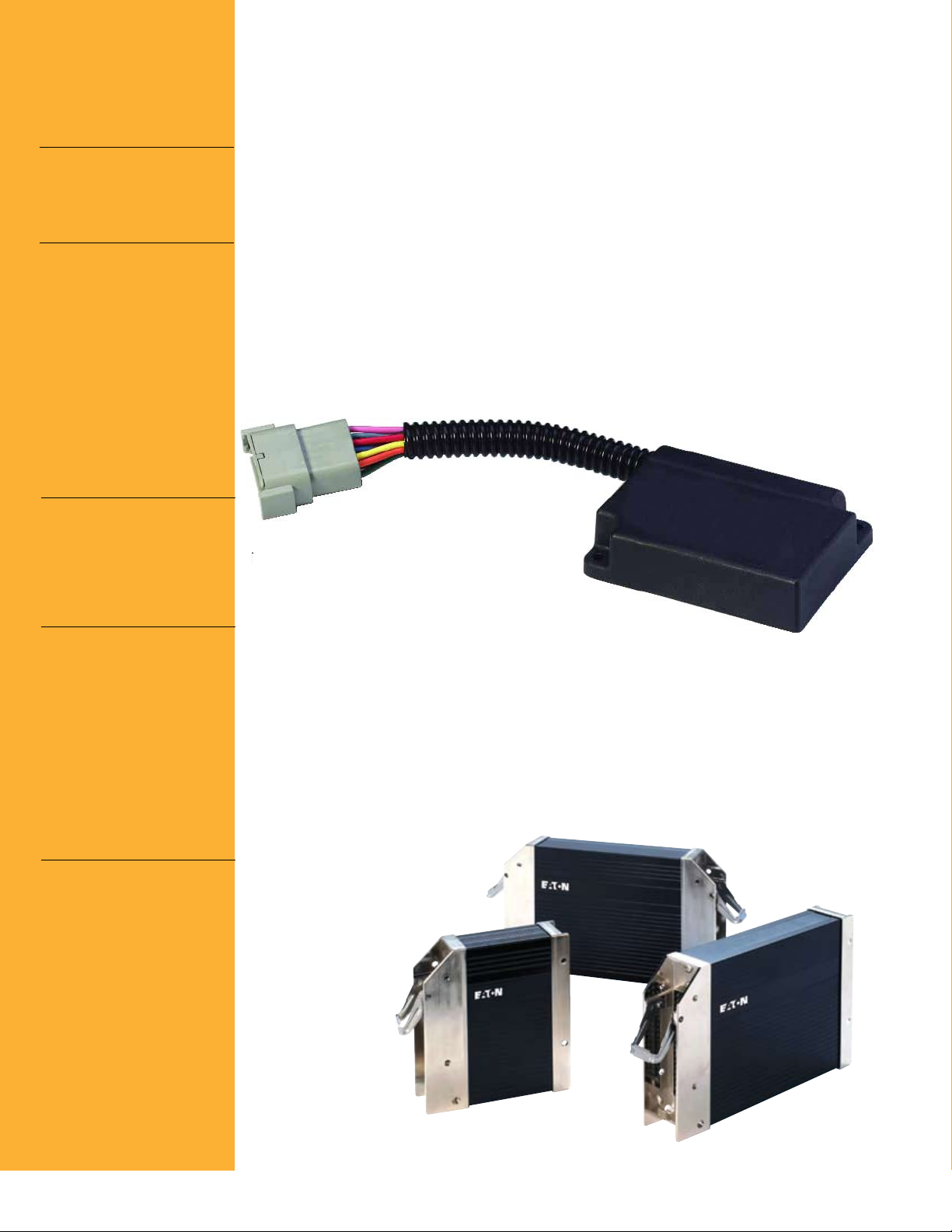
Electronic
Controller
Options
TCA Electronic Controller
The TCA at the heart of the
EH Fan Drive System, is a
rugged, fully encapsulated
digitally programmable controller specially designed for
mobile environments.
It is prepared for CANbus
communications on a ve-
hicle network. Software for
controlling the EH Fan Drive
System is loaded in the controller memory at the factory.
Control software parameters
are adjusted via RS 232 hook-
up to a laptop computer.
The TCA controller is available
for both 12 V or 24 V vehicle
power systems. With 5 con-
gurable inputs and 2 Pulse
Width Modulated (PWM)
outputs, the TCA can inter-
face with a variety of system
components and drive up to
two electro-hydraulic valves.
Outputs
• PWM current
controlled driver for
proportional flow control
• On-off driver for fan
off or fan reverse
Mechanical
• Polymer enclosure
• Fully encapsulated
electronics
• Flying lead harness
with 10-pin MetriPak
connector
• Two Mounting anges:
#8 fasteners
• Dual color LED for
status and diagnosis
Environment
• Operating temperature:
-40°C to +85°C
• Meets EMC standards
off-road vehicle
• Reverse battery and load
dump protection
• Input/output short circuit
protection
• UV resistant
• Water: temporary
immersion
• Random vibration
5.8 Grms
• Shock: 50 G
Two Channel Amplifier (TCA)
EFX Electronic Controller
Eaton EFX electronic controllers and I/O modules provide
a full range of electronic controls. With an array of controller options and I/O modules,
an EFX system can address
any application need. All EFX
products are IP67 rated and
are built for harsh mobile
and industrial application
environments. The EFX line is
programmed and congured
using Eaton CONTROL F(x)™
software.
EF(x) Controllers
Applications
Excavators, forestry,
telehandlers, utility vehicles,
cranes, ag machinery, paving
Specifications
Four different EFX controllers
and 3 I/O expansion modules
provide analog, digital, and
frequency inputs as well as
digital, PWM, and current-
controlled outputs. Each EFX
controller has both CANopen
and J1939 interfaces.
4 Eaton Electro-hydraulic Fan Drive System E-SYFD-MROO1-E3 October 2008
Page 5

Two Methods of Control 1. Integrated Fan Drive
System
Interface the Fan Drive
System to your engine
control module to execute
the cooling strategy exactly
as directed by the engine
control module.
2. Stand-alone Fan Drive
System
Dene your own cooling
logic using the TCA or EFX,
electronic controller.
By adding electronics to an
Eaton Electro-hydraulic Fan
Drive System, users can tailor the system to their needs.
Fan drive control parameters are adjusted through a
user-friendly graphical user
interface (GUI).
This GUI, the GUI for the TCA
is shown below, walks the
designer through the deni-
tion process with real-time
graphical feedback to clearly
indicate the system’s re-
sponse to each modication.
System data can also be
graphically monitored and
saved to verify actual
results. When the cooling
logic is fully dened,
resulting parameters are
saved and used for
exact system
duplication for your
production application.
Setup Screen
The Setup Screen feature
allows the user to dene his
own cooling logic by setting
in the required parameters.
Component Screen
The Component Screen gives
the user an overview of the
system and allows the user
to click on the components
and enter a description.
Monitor Screen
The Monitor Screen allows
the user to monitor the
system.
Control F(x)™
Programming Software
Eaton CONTROL F(x)
software allows you to
develop programs for
controlling electrohydraulic
components and systems.
Eaton provides control
function libraries based on
the IEC 61131-3 standard
that reduce application
development time. With the
CONTROL F(x) graphical
interface, you can create,
debug, and monitor the
control logic. This creates
a reliable system that can
be rapidly developed,
tested, implemented, and
maintained.
5 Eaton Electro-hydraulic Fan Drive System E-SYFD-MROO1-E3 October 2008
Page 6

Integrated
Fan Drive System
Inputs from sensors
and the engine
Fixed-displacement Pump
The system cooling strategy
is based on one ECM input,
two Temperature Inputs and
two Digital Inputs. In some
cases, the ECM signal is too
noisy or too weak to control
a hydraulic circuit. The TCA
or EFX solution amplies and
conditions the ECM signal to
be used on a hydraulic circuit.
TCA/EFX
A xed displacement pump
fan drive system is suited for
a smaller and simpler cooling
system. A xed displacement
pump is unable to alter it’s
displacement to slow the fan
speed with respect to the
cooling demand. The excess
flow generated by the pump
is returned to the tank, which
leads to generation of heat
and energy losses.
Fixed displacement pumps
are best suited for Fan Drive
Systems below 10 HP.
6 Eaton Electro-hydraulic Fan Drive System E-SYFD-MROO1-E3 October 2008
Page 7

Stand-Alone
Fan Drive System
Variable-displacement Pump
This system is similar to the
Fixed Displacement Pump
system. For engines not
equipped with an ECM, the
cooling strategy is based on
a temperature sensor and
digital inputs to the TCA.
A variable displacement
pump fan drive system is
suited for larger and more
complex cooling systems. A
variable displacement pump
reduces the displacement
to match the flow as per the
cooling demand. This feature
offers on-going energy savings
and creates less heating of
the hydraulic fluid.
Variable displacement
pumps are best suited
for Fan Drive Systems
above 20 HP.
TCA/EFX
Sensor Inputs
7 Eaton Electro-hydraulic Fan Drive System E-SYFD-MROO1-E3 October 2008
Page 8

Fan Drive System
Pump and Motor
Guide
powEr (Hp) 5 10 15 20 25 30 35 40 45 50+
Fixed Displacement Pumps
Eaton Gear 25500
Eaton Gear 26000
Eaton Gear GGP Aluminum
Vickers V10 Vane
Vickers V20 Vane
pumpSmotorS
Variable Displacement Pumps
Vickers Piston PVE
Eaton Piston 420
Vickers Piston PVH
Fixed Displacement Motors
Eaton Gear 26000
Eaton Gear GGP Aluminum (unidirectional)
Eaton Piston 74111
Eaton Piston 74318
Eaton Piston 74624
Eaton Piston HD
Vickers Vane MU2
Vickers Vane 25 M
6.6 - 30.6 cc
5.3 - 33.4 cc
3.3 - 22.8 cc
19.5 - 42.4
6.6 - 30.6 cc
5.3 - 33.4 cc
12.3 - 20.3 cc
21.6 - 25.4 cc
21.3 - 55.2 cc
25.2 • 41.0 • 45.1 cc
41.0 • 49.2 • 62.3 • 80 cc
57.4 • 73.7 • 98.3 • 131.1 cc
32.9 - 49.2 cc
54.4 - 105.5 cc
43.6 - 68.7 cc
82.6 cc
pumpS motorS
Gear
• High efciency design reduces ow-pressure ripple, noise, and vibration.
• Various shaft and porting options allow design exibility.
• Tandem and multi-section pump options minimize circuit cost.
• Compact envelope design reduces space required for installation.
• Integrated relief priority ow valve options reduce uid leak risks,
space requirements, and system costs.
Piston
• Versatile design includes single pumps, throughdrive arrangements, and
a variety of drive shaft and control options; adapts to many applications,
providing cost-effective variablepump installation.
• Proven components ensure longer life at the higher performance
levels of power-dense machinery.
• Compact housing and lightweight design allows better access for
installation and servicing.
• Heavy-duty bearing and shafts reduce internal deections and wear,
providing longer life and operation time.
• Designed for maximum efciency, directs more ow and input
energy to the work, not to heat and waste.
Vane
• Hydraulically balanced design increases the operating life of the
bushing/ bearing by eliminating side loads.
• Consistent efciency over life is achieved by self-compensation of
vane wear.
• Quieter operation as compared to a gear pump.
• Integrated pressure compensated ow control ensures priority and
constant flow regulation.
• Compact common inlet with double pump conguration allows
versatility in application. One can be used for steering and the other
for fan drive.
• Flexible port orientation allows easy installation and prevents hose bends.
• Vane pumps are the most commonly adopted steering pump in
on-highway vehicles.
Gear
• High efciency design reduces ow-pressure ripple, noise, and vibration.
• Various shaft and porting options allow design exibility.
• Tandem and multi-section pump options minimize circuit cost.
• Compact envelope design reduces space required for installation.
• Integrated relief priority ow valve options reduce uid leak risks,
space requirements, and system costs.
Piston
• Compact design reduces space required for installation.
• Lightweight durable housing minimizes system mass.
• Numerous shaft and porting options provide design versatility.
• Bi-directional rotation allows reversal of fan direction.
• Integral speed sensor available to provide optional closed-loop control
of fan speed.
• Fine tolerances reduce leakage and increase system efciency.
• Low start-up torque requires less pressure build-up for operation.
Vane
• Lower starting torque as compared to gear and piston motors.
• Smoother operation with lesser jerks as compared to gear motors.
• Excellent capability to handle pressure shocks.
• Better efciency at low RPM.
• No back pressure requirements as opposed to those in piston motors.
• Quieter operation with respect to gear and piston motors.
8 Eaton Electro-hydraulic Fan Drive System E-SYFD-MROO1-E3 October 2008
Page 9

Fan Drive System
Hydraulic
Components
Gear Motor
• Fixed-displacement
• 50 cc
• 100 Series
Vane Pump
• Fixed-displacement
• 3.3 cc to 42.5 cc
• V10 Series,
V20 Series
Piston Pump
• Variable-displacement
• 25, 40, 45 cc
• 420 Series
Vane Motor
• Fixed-displacement
• 21.6 cc to 68.7 cc
• MU2 Series,
25 M Series
Piston Pump
• Variable-displacement
• 18, 20, 45, 50 cc
• PVM Series
Gear Pump
• Fixed-displacement
• 7-30 cc, 21-100 cc
• 26000 Series,
25500 Series
Piston Motor
• Fixed-displacement
• 12, 20 cc
• 74100 Series
Piston Motor
• Fixed-displacement
• 33, 49 cc
• 74300 Series
Hose & Fittings
Piston Motor
• Fixed-displacement
• 83 cc
• 74600 Series
Filter
• Return-line lter
• 57 L/min, 95 L/min,
227 L/min
• OFRS 25
Proportional Compensator
• Bolt-on electro-hydraulic
control element
• Piston pump fan
drive control
Reservoir
• Reduced size
• 3L, 70 L/min
• AGT Cyclone tank
®
STC
• Snap-to-connect
• Threadless connectors
EZ Torque
• Quick, easy install,
ergonomically friendly
• Fewer total parts
9 Eaton Electro-hydraulic Fan Drive System E-SYFD-MROO1-E3 October 2008
Page 10

Engineered
Systems
Other electro-hydraulic
systems for steering,
work circuit and fan drive
applications.
Electro-hydraulic Steer By
Wire (EH-SBW)
EH-SBW is a new technology
steering system for vehicles
where an electronic sensor
replaces the rotary steering
valve of a traditional hydraulic
steering system. An electrical
signal, rather than mechanical
or fluid connections, transfers the steering command
from the operator’s steering
wheel to the steered wheel
electrohydraulic actuator.
The Eaton system includes a
novel tactile feedback device
at the steering wheel that
simulates the feel of conventional hydrostatic steering.
Additional Benefits:
• Hydraulic leaks and noise
are reduced.
• Assembly is simplied, providing greater cab design
exibility.
• Productivity, safety, and er-
gonomics are all improved.
• The tailoring of steering
characteristics by re-pro-
gramming is simplied.
Electro-hydraulic Work
Circuits
An electronic remote control
joystick replaces the hydraulic
remote control, cables and
levers of a traditional work
circuit operator interface. An
electrical signal, rather than
mechanical or fluid connections, transfers the boom,
bucket or implement command from the operator’s
joystick to an electro-hydraulic directional control valve.
Other work circuit applications include control of auxiliary motors, power take-off
clutches, and transmissions.
Additional Benefits:
• The work circuit control is
more accurate and stable.
• Hydraulic noise and leaks in
the cab are reduced.
• Hydraulic connections are
eliminated or simplied.
• Vehicle energy manage-
ment is improved.
The Electronic Transmission
Automotive Control (ETAC)
ETAC system is a hydrostatic
propulsion package ideally
suited for small to medium
sized fork lift trucks, tractors
and utility vehicles. ETAC
matches engine power to the
vehicle propulsion and work
requirement. The “Maestro”
digital, programmable controller is integrated with the
throttle system as well as a
closed circuit hydraulic pump
and motor. Maestro drives a
high performance electrohydraulic interface on the pump
and uses a swashplate sensor to provide precise, closed
loop control.
Additional Benefits:
• Consistent performance
over a wide range of operating temperatures.
• Hydrostatic braking is adjustable through software.
• Inching function maximizes
productivity by allowing the
operator to regulate work
circuit pump flow independently of vehicle speed.
• Anti-stall enables use of
available engine power
by automatically reducing
pump displacement.
• Adjustment of software parameters allows new operators to operate the vehicle
with the same productivity
as skilled drivers.
10 Eaton Electro-hydraulic Fan Drive System E-SYFD-MROO1-E3 October 2008
Page 11

Tailored to
Your Needs
World Class Product Lines
and Systems
Aeroquip
Char-Lynn
Eaton
Vickers
Weatherhead
®
®
®
®
®
Eaton is a global diversified industrial
manufacturer. Eaton is a leader in:
• Fluid power systems
• Electrical power quality, distribution and control
• Automotive engine air management and fuel economy
• Intelligent truck systems for fuel economy and safety
For more information, visit www.eaton.com.
11 Eaton Electro-hydraulic Fan Drive System E-SYFD-MROO1-E3 October 2008
Page 12

Eaton
Hydraulics Operations USA
14615 Lone Oak Road
Eden Prairie, MN 55344
USA
Tel: 952-937-9800
Fax: 952-294-7722
www.eaton.com/hydraulics
© 2008 Eaton Corporation
All Rights Reserved
Printed in USA
Document No. E-SYFD-MR001-E3
Supersedes E-SYFD-MR001-E2
October 2008
Eaton
Hydraulics Operations Europe
Route de la Longeraie 7
1110 Morges
Switzerland
Tel: +41 (0) 21 811 4600
Fax: +41 (0) 21 811 4601
Eaton
Hydraulics Operations Asia Pacific
11th Floor Hong Kong New World Tower
300 Huaihai Zhong Road
Shanghai 200021
China
Tel: 86-21-6387-9988
Fax: 86-21-6335-3912
 Loading...