

Page 1

Steering Catalog
Steering Control Units
Torque Generators
Steering Columns
Page 2

2 EATON Char-Lynn Steering Catalog C-STOV-MC001-E1 July 2006
Literature Referenced in this Catalog:
• Eaton Technical Bulletin 3-401
• Eaton Flow Divider Catalog E-VLFL-MC001-E
• Eaton Relief Valve Catalog 11-510
• Eaton Gear Pumps Series 26 Model 26000 Catalog 11-609
• Eaton Char-Lynn Low Speed High Torque Motors Catalog E-MOLO-MC001-E2
• Vick ers
®
Screw in Cartridge Values Catalog V-VLOV-MC001-E2
• Vick ers
®
Proportional Valves Catalog 539
• Vickers Solenoid Operated Directional Valves Catalog GB-C-2015
Page 3

EATON Char-Lynn Steering Catalog C-STOV-MC001-E1 July 2006 3
Table of
Contents
Description and Technologies About Power Steering
Description and Advantages . . . . . . . . . . . . . . . . . . . . . . . . . . . . . . . . . . . . . . . . . . . . . . . . . . . . . . . . . . . . . . . . . . . . . . . . . . . . . . . 4
Hydraulic Circuit Explanation . . . . . . . . . . . . . . . . . . . . . . . . . . . . . . . . . . . . . . . . . . . . . . . . . . . . . . . . . . . . . . . . . . . . . . . . . . . . 6-11
Neutral Circuits
Open Center . . . . . . . . . . . . . . . . . . . . . . . . . . . . . . . . . . . . . . . . . . . . . . . . . . . . . . . . . . . . . . . . . . . . . . . . . . . . . 6
Open Center Power Beyond . . . . . . . . . . . . . . . . . . . . . . . . . . . . . . . . . . . . . . . . . . . . . . . . . . . . . . . . . . . . . . . . 6
Closed Center . . . . . . . . . . . . . . . . . . . . . . . . . . . . . . . . . . . . . . . . . . . . . . . . . . . . . . . . . . . . . . . . . . . . . . . . . . . . 7
Load Sensing (static and dynamic signal) . . . . . . . . . . . . . . . . . . . . . . . . . . . . . . . . . . . . . . . . . . . . . . . . . . . . . 8
Work Circuits
Non-Load Reaction . . . . . . . . . . . . . . . . . . . . . . . . . . . . . . . . . . . . . . . . . . . . . . . . . . . . . . . . . . . . . . . . . . . . . . . 11
Load Reaction . . . . . . . . . . . . . . . . . . . . . . . . . . . . . . . . . . . . . . . . . . . . . . . . . . . . . . . . . . . . . . . . . . . . . . . . . . . 11
Steering Units with Integral Valves . . . . . . . . . . . . . . . . . . . . . . . . . . . . . . . . . . . . . . . . . . . . . . . . . . . . . . . . . . . . . . . . . . . . . . . . . 12
Special Features and Application. . . . . . . . . . . . . . . . . . . . . . . . . . . . . . . . . . . . . . . . . . . . . . . . . . . . . . . . . . . . . . . . . . . . . . . . 13-18
Manual Steering. . . . . . . . . . . . . . . . . . . . . . . . . . . . . . . . . . . . . . . . . . . . . . . . . . . . . . . . . . . . . . . . . . . . . . . . . . . . . . . . . 13
2 Speed . . . . . . . . . . . . . . . . . . . . . . . . . . . . . . . . . . . . . . . . . . . . . . . . . . . . . . . . . . . . . . . . . . . . . . . . . . . . . . . . . . . . . . . 14
Dual Displacement. . . . . . . . . . . . . . . . . . . . . . . . . . . . . . . . . . . . . . . . . . . . . . . . . . . . . . . . . . . . . . . . . . . . . . . . . . . . . . . 15
Eaton Patented Technologies
Q-Amp (Flow Amplification) . . . . . . . . . . . . . . . . . . . . . . . . . . . . . . . . . . . . . . . . . . . . . . . . . . . . . . . . . . . . . . . . . . . . . . . 16
Wide Angle. . . . . . . . . . . . . . . . . . . . . . . . . . . . . . . . . . . . . . . . . . . . . . . . . . . . . . . . . . . . . . . . . . . . . . . . . . . . . . . . . . . . . 18
Cylinder Damping . . . . . . . . . . . . . . . . . . . . . . . . . . . . . . . . . . . . . . . . . . . . . . . . . . . . . . . . . . . . . . . . . . . . . . . . . . . . . . . 19
VersaSteer . . . . . . . . . . . . . . . . . . . . . . . . . . . . . . . . . . . . . . . . . . . . . . . . . . . . . . . . . . . . . . . . . . . . . . . . . . . . . . . . . . . . . 20
STC Direct Porting . . . . . . . . . . . . . . . . . . . . . . . . . . . . . . . . . . . . . . . . . . . . . . . . . . . . . . . . . . . . . . . . . . . . . . . . . . . . . . . 21
Steering Control Units and Torque Generators
Series 5. . . . . . . . . . . . . . . . . . . . . . . . . . . . . . . . . . . . . . . . . . . . . . . . . . . . . . . . . . . . . . . . . . . . . . . . . . . . . . . . . . . . . . . . 22
Series 10. . . . . . . . . . . . . . . . . . . . . . . . . . . . . . . . . . . . . . . . . . . . . . . . . . . . . . . . . . . . . . . . . . . . . . . . . . . . . . . . . . . . . . . 29
Series 20 . . . . . . . . . . . . . . . . . . . . . . . . . . . . . . . . . . . . . . . . . . . . . . . . . . . . . . . . . . . . . . . . . . . . . . . . . . . . . . . . . . . . . . 37
Series 25 . . . . . . . . . . . . . . . . . . . . . . . . . . . . . . . . . . . . . . . . . . . . . . . . . . . . . . . . . . . . . . . . . . . . . . . . . . . . . . . . . . . . . . 44
Series 40 . . . . . . . . . . . . . . . . . . . . . . . . . . . . . . . . . . . . . . . . . . . . . . . . . . . . . . . . . . . . . . . . . . . . . . . . . . . . . . . . . . . . . . 49
Torque Generator. . . . . . . . . . . . . . . . . . . . . . . . . . . . . . . . . . . . . . . . . . . . . . . . . . . . . . . . . . . . . . . . . . . . . . . . . . . . . . . . 53
Steering System Components and System Accessories
Antijerk Valves . . . . . . . . . . . . . . . . . . . . . . . . . . . . . . . . . . . . . . . . . . . . . . . . . . . . . . . . . . . . . . . . . . . . . . . . . . . . . . . . . .64
Priority Valves VLC, VLE, VLH . . . . . . . . . . . . . . . . . . . . . . . . . . . . . . . . . . . . . . . . . . . . . . . . . . . . . . . . . . . . . . . . . . . . . .65
Check Valves . . . . . . . . . . . . . . . . . . . . . . . . . . . . . . . . . . . . . . . . . . . . . . . . . . . . . . . . . . . . . . . . . . . . . . . . . . . . . . . . . . . .69
Relief Valves . . . . . . . . . . . . . . . . . . . . . . . . . . . . . . . . . . . . . . . . . . . . . . . . . . . . . . . . . . . . . . . . . . . . . . . . . . . . . . . . . . . . 71
Columns . . . . . . . . . . . . . . . . . . . . . . . . . . . . . . . . . . . . . . . . . . . . . . . . . . . . . . . . . . . . . . . . . . . . . . . . . . . . . . . . . . . . . . . 72
Steering Wheels and Accessories. . . . . . . . . . . . . . . . . . . . . . . . . . . . . . . . . . . . . . . . . . . . . . . . . . . . . . . . . . . . . . . . . . . 82
EH Proportional Steer Valves . . . . . . . . . . . . . . . . . . . . . . . . . . . . . . . . . . . . . . . . . . . . . . . . . . . . . . . . . . . . . . . . . . . . . . 85
Four Wheel Steer Switching Valves . . . . . . . . . . . . . . . . . . . . . . . . . . . . . . . . . . . . . . . . . . . . . . . . . . . . . . . . . . . . . . . . . 86
Flow Divider Valves . . . . . . . . . . . . . . . . . . . . . . . . . . . . . . . . . . . . . . . . . . . . . . . . . . . . . . . . . . . . . . . . . . . . . . . . . . . . . . 87
Brake Valves . . . . . . . . . . . . . . . . . . . . . . . . . . . . . . . . . . . . . . . . . . . . . . . . . . . . . . . . . . . . . . . . . . . . . . . . . . . . . . . . . . . . 88
T Series Hydraulic Motors . . . . . . . . . . . . . . . . . . . . . . . . . . . . . . . . . . . . . . . . . . . . . . . . . . . . . . . . . . . . . . . . . . . . . . . . 89
Sizing and Application
Ackermann Type Steering . . . . . . . . . . . . . . . . . . . . . . . . . . . . . . . . . . . . . . . . . . . . . . . . . . . . . . . . . . . . . . . . . . . . . . . . . 89
Articulated Type Steering . . . . . . . . . . . . . . . . . . . . . . . . . . . . . . . . . . . . . . . . . . . . . . . . . . . . . . . . . . . . . . . . . . . . . . . . . 92
Articulated Vehicle Steering Analysis Form. . . . . . . . . . . . . . . . . . . . . . . . . . . . . . . . . . . . . . . . . . . . . . . . . . . . . . . . . . . 93
Articulated Vehicle Steering Analysis Form. . . . . . . . . . . . . . . . . . . . . . . . . . . . . . . . . . . . . . . . . . . . . . . . . . . . . . . . . . . 95
Information contained in this publication is accurate as of the publication date and is subject to change without notice. Performance values are typical values. Customers are responsible for selecting
products for their applications using normal engineering methods.
Page 4

4 EATON Char-Lynn Steering Catalog C-STOV-MC001-E1 July 2006
Description and
Advantages
Steering Control Units
The Char-Lynn®steering control unit (SCU) is fully
fluid linked. This means there is no mechanical
connection between the steering unit, the pump
and the steering cylinders. The unit consists of a
manually operated directional control servo valve
and feedback meter element in a single body. It is
used principally for fluid linked power steering
systems but it can be used for some servo-type
applications or any application where visual
positioning is required. The close coupled, rotary
action valve performs all necessary fluid directing
functions with a small number of moving parts.
The manually actuated valve is coupled with the
mechanical drive to the meter gear. The control is
lubricated and protected by the power fluid in the
system and can operate in many environments.
Char-Lynn power steering control units offer the
following advantages:
• Minimizes steering linkage—reduces cost, provides
flexibility in design.
• Provides complete isolation of load forces from the
control station—provides operator comfort.
• Provides continuous, unlimited control action with
very low input torque.
• Provides a wide selection of control circuits and
meter sizes.
• Can work with many kinds of power steering pumps
or fluid supply.
SERIES 5 (291-XXXX-XXX, 292-XXXX-XXX, 293-XXXX-XXX, 294-XXXX-XXX)
Displacement 31.5 - 146 cm3/r 1.92 - 8.9 in3/r
Flow 11 - 19 l/min 3 - 5 GPM
Pressure 140 bar 2030 PSI
SERIES 10 (200-XXXX-XXX, 220-XXXX-XXX)
Displacement 58.7 - 739 cm3/r 3.58 - 45.1 in3/r
Flow 11 - 76 l/min 3 - 20 GPM
Pressure 275 bar 4000 PSI
SERIES 20 (236-XXXX-XXX)
Displacement 60 - 985 cm3/r 3.6 - 60 in3/r
Flow 38 - 114 l/min 10 - 30 GPM
Pressure 241 bar 3500 PSI
SERIES 25 (251-XXXX-XXX, 252-XXXX-XXX, 253-XXXX-XXX)
Displacement 490 - 1230 cm3/r 30 - 75 in3/r
Flow 95 - 151 l/min 25 - 40 GPM
Pressure 241 bar 3500 PSI
SERIES 40 (281-XXXX-XXX, 282-XXXX-XXX, 283-XXXX-XXX)*
Displacement 1230 - 3030 cm3/r 75 - 185 in3/r
Flow 151 - 227 l/min 40 - 60 GPM
Pressure 241 bar 3500 PSI
* For all other product numbers consult steering website.
Page 5

EATON Char-Lynn Steering Catalog C-STOV-MC001-E1 July 2006 5
Description and
Advantages
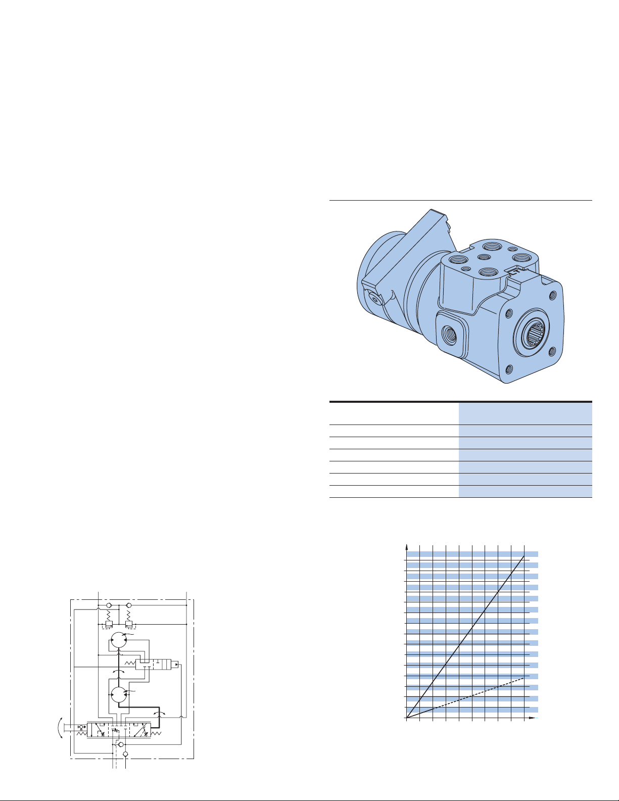
Torque Generator
Char-Lynn torque generators have been completely
redesigned to meet the needs of the changing
marketplace. These torque generators have served
the industry well, providing:
• Power assist for vehicle steering
• Power assist on gates and valves, eliminating the
large hand wheels
• Powerful rotary motion with effortless manual rotary
input on numerous other applications
Today’s market includes power steering on electric lift
trucks. These new torque generators have been designed
with features that greatly improve the operator’s comfort as
well as the vehicle’s performance.
Use the Torque Generator as rotary power assist for:
• Large indexing tables
• Manually operated gates and valves
• Manual positioning devices
• Mechanical steering systems
• T urntables
SERIES 217, 227
Displacement 76 - 160 cm3/r 4.7 - 9.6 in3/r
Flow 15 l/min 4 GPM
Pressure 69 and 172 bar 1000 and 2500 PSI
STEERING COLUMNS (204-XXXX-XXX)
Jacket Length 56 - 836 mm 2.2 - 33 inch
Horn Wire with and without with and without
Upper Ends 10 Upper End Types 10 Upper End Types
Customized Steering Columns
Char-Lynn columns can be custom built to your
exact specifications. The column and mounting
flange is of a sturdy single weldment design. These
columns have high thrust and side load capacity
with low shaft torsional friction. A tilt column is
also available.
Page 6
6 EATON Char-Lynn Steering Catalog C-STOV-MC001-E1 July 2006
Hydraulic Circuit
Explanation
Neutral Circuits:
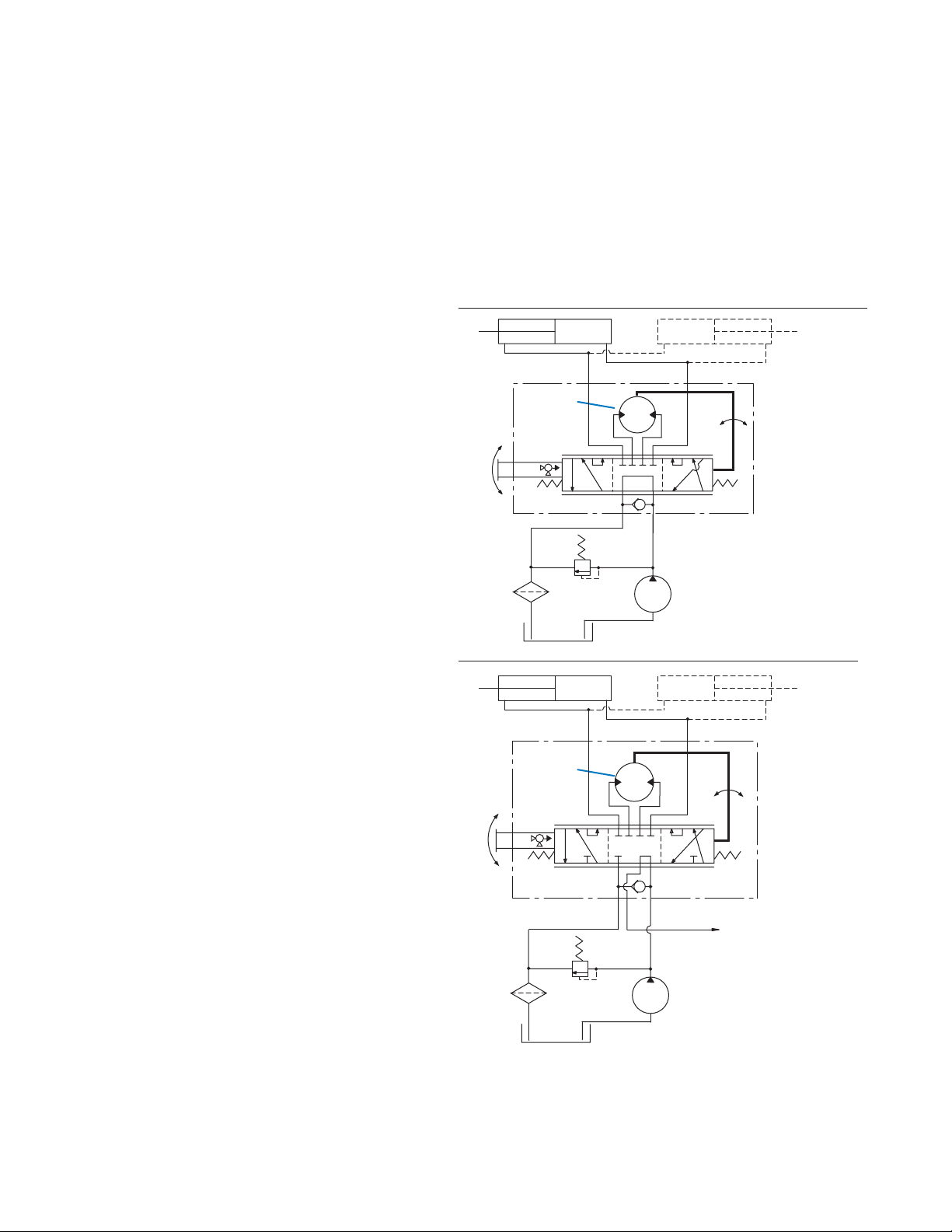
Open Center
and Open Center
Power Beyond
Open Center
• Simplest, most
economical system
• Uses a fixed
displacement pump
• In neutral position
pump and tank are
connected
• Most suitable on
smaller type vehicles
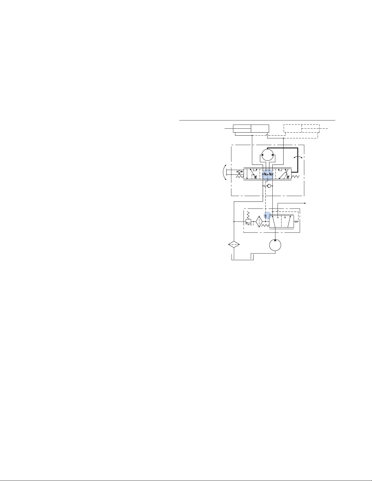
Open Center Power Beyond
The power beyond steering
control unit supplies steering
and auxiliary valve functions.
The power beyond unit is
used on medium pressure,
open center (fixed
displacement pump) systems.
When not steering, the power
beyond unit directs all inlet
flow to the auxiliary circuit.
However once steering is
initiated, part of the auxiliary
flow is diverted to steering.
Since steering has priority, all
flow, if required, will be
diverted to steering. The tank
port of the steering unit has
flow only when steering is
operated. Thus, flow out of
the auxiliary (“PB”) port and
the tank port will fluctuate or
stop depending on steering
input.
The following special
considerations should be
addressed when applying
power beyond steering:
• Auxiliary valves
(connected to PB) must
be open center type.
Slight bump or kick may
be felt in steering
wheel when auxiliary
functions are activated
during steering
operations.
• Pump flow not used for
steering is available at
power beyond (PB)
outlet, except at
steering stops where
total pump flow goes
over the system relief
valve. Avoid auxiliary
functions that require
constant flow while
steering.
• Flow is only directed to
the tank port when
steering is operated.
Avoid systems where
return flow from tank
port is used for auxiliary
functions.
• Inlet pressure to the
steering unit will be the
higher of steering
system pressure or
auxiliary valve pressure.
• Generally avoid
systems where heavy
use of auxiliary
functions occur while
steering.
Applications
• Lawn and Garden
Equipment
• Utility Vehicles
LR
Gerotor
T
LR
Gerotor
T
PB
P
Fixed
Displacement
Pump
P
To Auxilliary Circuit
Open Center Valves
Fixed
Displacement
Pump
Page 7
EATON Char-Lynn Steering Catalog C-STOV-MC001-E1 July 2006 7
Hydraulic Circuit
Explanation
Neutral Circuits:
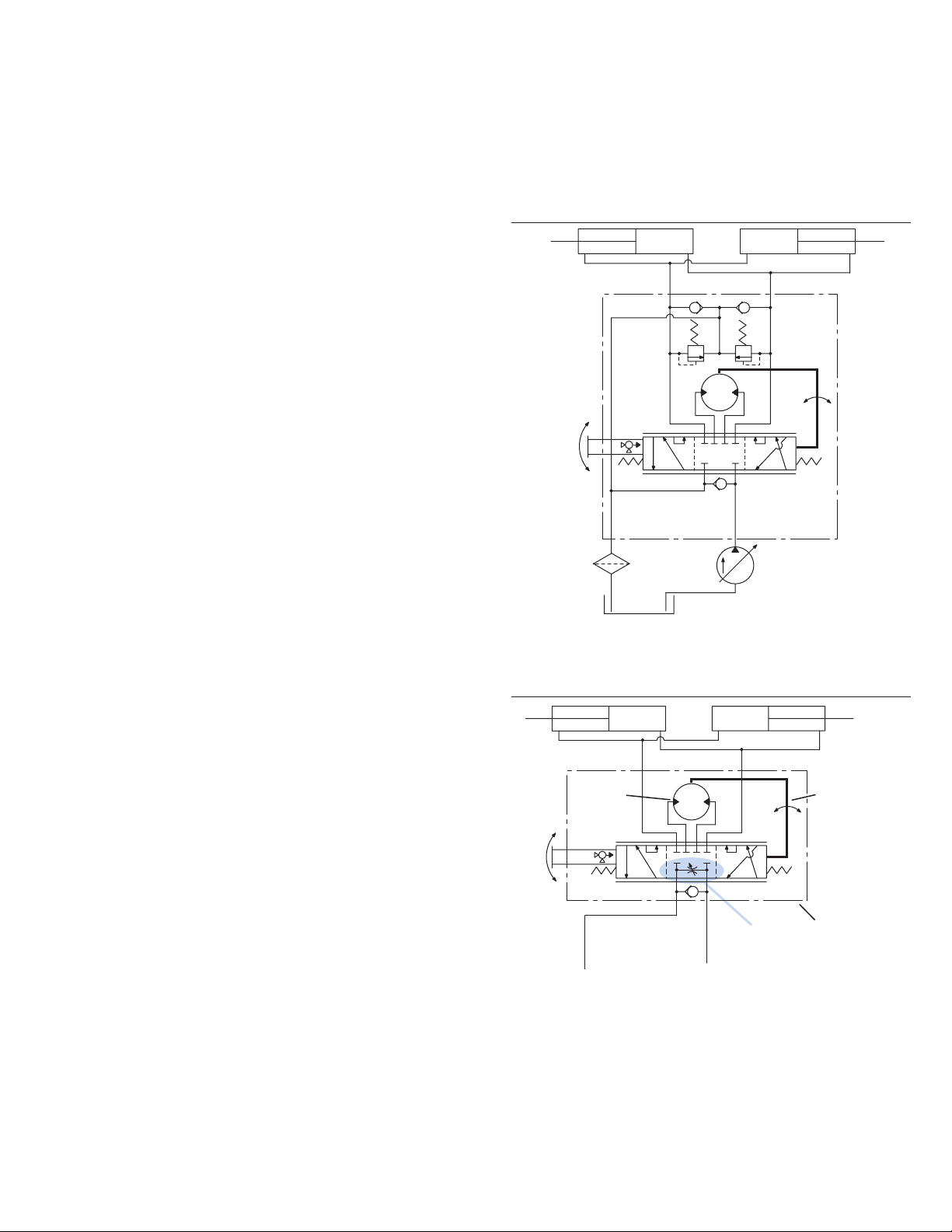
Closed Center
Closed Center
• Uses a pressure
compensated variable
displacement pump
• In neutral position
pump and tank are
disconnected
• Most suitable on large
construction equipment
Valve Option A
Closed Center System
Pressure
Compensated
Pump
P
RL
T
Closed Center with
Neutral Bleed
Neutral Bleed Feature
Closed Center Steering
Control Units are available
with and without neutral
bleed feature. Most
applications may not require
the bleed feature, however,
the maximum temperature
differential between
components within the
steering circuit must not
exceed specification (50° F or
28° C). Order unit with the
bleed feature if the
temperature differential may
exceed this limit. The neutral
bleed feature allows a small
flow of fluid to pass through
the unit when in neutral to
reduce the thermal
diff erential.
Typical applications where
neutral bleed is required are:
• Remote steering
position from power
source.
• Extended engine idle
operation when vehicle
is parked.
• High duty cycle
operation sharing a
common reservoir with
the steering circuit.
Applications
• Construction Industry
RL
Gerotor
Metering
Mechanism
T
P
with
Neutral
Bleed
Direct
Mechanical
Link
Steering
Control
Unit
Page 8
8 EATON Char-Lynn Steering Catalog C-STOV-MC001-E1 July 2006
Hydraulic Circuit
Explanation
Neutral Circuits:
Load Sensing
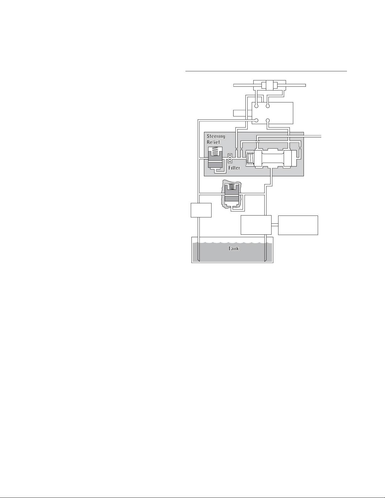
Load Sensing Circuits
Char-Lynn load sensing
power steering uses
conventional or load sensing
power supplies to achieve
load sensing steering. The
use of a load sensing
steering unit and a priority
valve in a normal power
steering circuit offers the
following advantages:
• Provides smooth
pressure compensated
steering because load
variations in the
steering circuit do not
affect axle response or
maximum steering rate.
• Provides true power
beyond system
capability by splitting
the system into two
independent circuits.
Pressure transients are
isolated in each circuit.
Only the flow required
by the steering
maneuver goes to the
steering circuit. Flow
not required for
steering is available for
use in the auxiliary
circuits.
• Provides reliable operation
because the steering
circuit always has flow
and pressure priority.
Char-Lynn load sensing
steering control units and
priority valves can be used with
open center , closed center or
load sensing systems. Use in
an open center system with a
fixed displacement pump or a
closed center system with a
pressure compensated pump,
offers many of the features of a
load sensing system. Excess
flow is available f or auxiliary
circuits.
Listed below are the
components of a typical load
sensing control circuit and a
brief application description.
Pump—May be fixed
displacement, pressure
compensated,
or flow and pressure
compensated design.
Prior ity V alve—Sized for
design pressure drop at
maximum pump output flow
rate and priority flow
requirements. The minimum
control pressure must assure
adequate steering flow rate
and must be matched with
the steering control unit.
A dynamic signal priority
valve must be used with a
dynamic signal steering
control unit.
Steering Control Unit—
Designed for specific rated
flows and control pressures.
It must be matched with a
control pressure in the
priority valve to obtain
maximum steering rates.
Higher flow rates require
higher control pressures.
Neutral internal bleed
assures component
temperature equalization.
LS Line—A LS line is always
needed to sense pressure
downstream from the
variable control orifice in the
steering control unit. This is
balanced by an internal
passage to the opposite side
of the priority control spool.
The total system
performance depends on
careful consideration of the
control pressure chosen and
pressure drop in the CF line.
Steering Relief Valve—
Must be factory set at least
10 bar [145 PSl] above the
maximum steering cylinder
pressure requirement. Most
of the flow will be directed
to the auxiliary circuit (EF)
when the relief setting is
exceeded.
System Main Relief
Valve—A pressure relief
valve for the auxiliary circuit
and/or a main safety valve for
the protection of the pump is
recommended and sized for
the maximum pump output
flow rate. If a main relief valve
is used, it must be set above
the priority circuit steering
relief valve pressure setting.
LS— Load Sensing
DS— Dynamic Signal
PP— Pilot Pressure
CF— Control Flow
EF — Excess Flow
Manual
Input
LS
T
Filter
Steering Cylinder
LR
TP
DSLS
Main
Relief
P
Pump Prime Mover
Load Sensing
Steering Unit
CF
PP
Priority Valve
Dynamic Signal
High Pressure
Carryover
EF
Page 9
EATON Char-Lynn Steering Catalog C-STOV-MC001-E1 July 2006 9
Hydraulic Circuit
Explanation
Neutral Circuits:
Load Sensing
Dynamic Signal—
Open Center Pump
Dynamic Signal—
Load Sensing Pump
Load Sensing Circuits—
Signal Systems
Two types of load sensing
signal systems are
available—Dynamic and
Static.
Dynamic Signal—Used for
more difficult applications.
The dynamic signal systems
offer the following benefits:
• Faster steering
response.
• Improved cold weather
start-up performance.
• Increased flexibility to
solve problems related
to system performance
and stability.
Dynamic
Signal
RL
Load
Sensing
(Dynamic
Signal)
Steering
Control Unit
(non-load
LS P
T
LS CF EF
T
P
Fixed Displacement Pump
Load Sensing Steering System with Fixed
Displacement Pump (Open Center Circuit)
reaction)
High Pressure
Carryover to
Auxiliary Circuit with
Open Center Valve(s)
Priority Valve
(Dynamic Signal)
Dynamic
Signal
T
Shuttle Valve
RL
Load
Sensing
(Dynamic
Signal)
Steering
Control Unit
(non-load
TLSP
LS CFEF
P
Pressure and Flow
Compensated Pump
Load Sensing Steering System with Pressure and Flow
Compensated Pump (Closed Center, Load Sensing Circuit)
reaction)
Auxiliary
Circuit with
Load Sensing
Valve(s)
Priority Valve
(Dynamic Signal)
Pilot Signal
from Auxiliary
Circuit
Page 10
10 EATON Char-Lynn Steering Catalog C-STOV-MC0 01-E1 July 2006
Static Signal—
Open Center Pump
Static Signal—Used for
conventional applications
where response or circuit
stability is not a problem.
The load sensing pilot line
should not exceed 2 meters
[6 feet] in length.
Hydraulic Circuit
Explanation
Neutral Circuits:
Load Sensing
Static Signal
RL
Load
Sensing
(Static
Signal)
Steering
Control Unit
(non-load
TLS P
LS CF EF
T
P
Fixed Displacement Pump
Load Sensing Steering System with
Fixed Displacement Pump
(Open Center Circuit)
reaction)
Auxiliary
Circuit with
Open Center
Valve(s)
Priority Valve
(Static Signal)
Page 11

EATON Char-Lynn Steering Catalog C-STOV-MC001-E1 July 2006 11
Hydraulic Circuit
Explanation
Work Circuits:
Non-Load Reaction
and Load Reaction
Non-Load Reaction
A non-load reaction steering
unit blocks the cylinder ports
in neutral, holding the axle
position whenever the
operator releases the
steering wheel.
Load Reaction
A load reaction steering unit
couples the cylinder ports
internally (in the neutral
position) with the meter
gear set. Axle forces are
then allowed to return the
steering wheel to its
approximate original
position. Comparable to
automobile steering,
gradually releasing the
wheel mid turn will allow
the steering wheel to spin
back as the vehicle
straightens.
The cylinder system used
with load reaction units
must have equal oil
volume displaced in both
directions. The cylinders
should be a parallel pair (as
shown) or one double rod
end unit. Do not use with a
single unequal area
cylinder system.
Gerotor
Metering
Mechanism
RL
Direct
Mechanical
Link
Gerotor
Metering
Mechanism
T
Closed Center System
Non-Load Reaction Circuit
P
Steering
Control
Unit
Pressure and Flow
Compensated Pump
RL
T
P
Fixed
Displacement
Pump
Direct
Mechanical
Link
Steering
Control
Unit
Open Center System
Load Reaction Circuit
Page 12
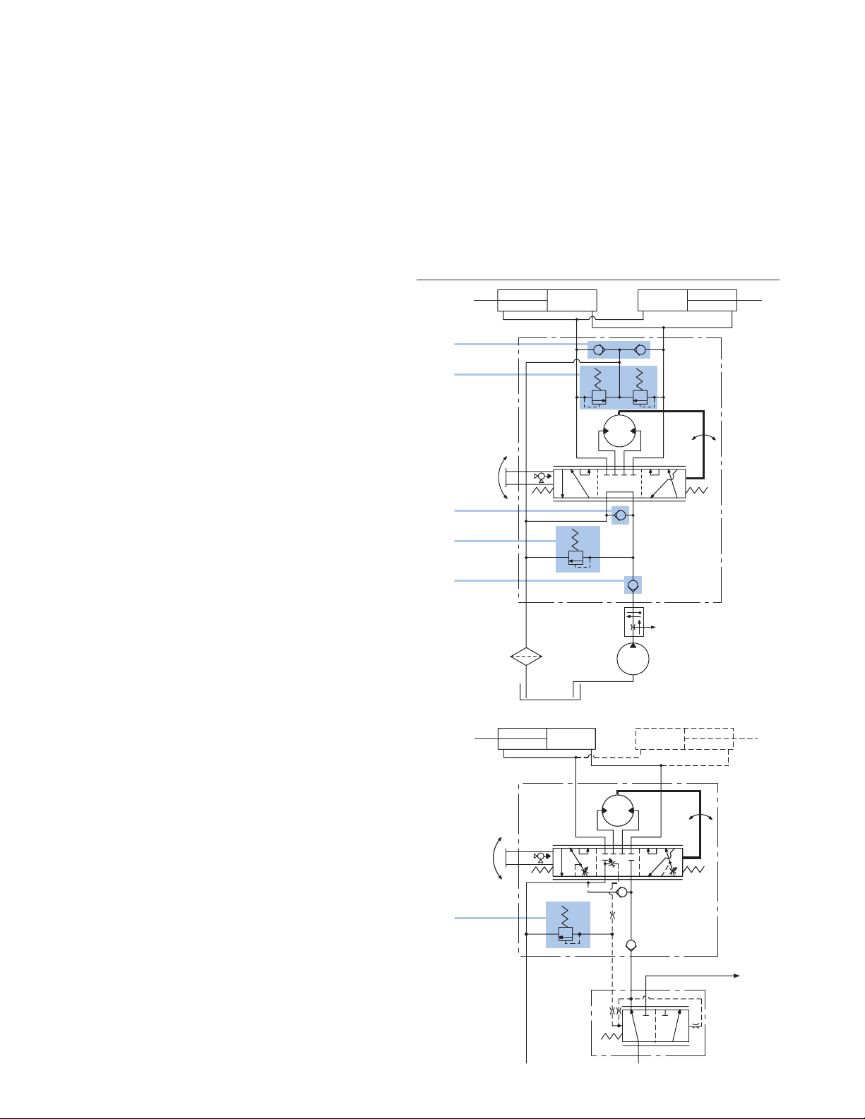
12 EATON Char-Lynn Steering Catalog C-STOV-MC0 01-E1 July 2006
Steering Units
with Integral
Valves
Integral valves are available
for the Char-Lynn steering
control unit. Included are:
Inlet Relief Valve, Cylinder
Port Shock Valves, LS-Relief
Valve, and Anti-Cavitation
Valves for cylinder ports. In
addition, a Manual Steering
Check V alv e for limited
manual steering is included.
The integral valves eliminate
the need for a separate
valve block, and provides
versatility to meet any
steering circuit standard.
Valve Description:
1 Anti-cavitation check
valve for cylinder ports—
(R & L) protects steering
circuit against vacuum
(cavitation) conditions.
2 Cylinder Port Relief
Valves—(R & L) protects
hoses against pressure
surge created by ground
forces on the steered axle.
3 Manual Steering Check
Valve—converts unit to a
hand operated pump for
limited manual steering.
Included in all units except
Series 20, 25, and 40.**
4 Inlet Relief Valve—limits
maximum pressure drop
across the steering unit
protecting the steering
circuit.
5 Inlet Check Valve—
prevents oil from returning
through the steering unit
when pressure on the
cylinder side is greater
than pressure on the inlet
side to prevent steering
wheel kick.
6 LS-Relief Valve—Limits
maximum pressure in the
steering circuit (LS units
only)
**Steering units with displacements larger than
185 cm
3
/r [11.3 in3/r] may require a separate
power source for limited operation.
1
2
3
4
5
EF
6
Page 13
EATON Char-Lynn Steering Catalog C-STOV-MC001-E1 July 2006 13
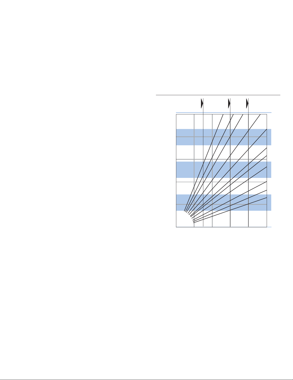
Special Features
and Application
Manual Steering
96
[5.9]
74
[4.5]
59
[3.6]
46
[2.8]
185
[11.3]
146
[8.9]
160
[9.7]
230
[14.1]
295
[17.9]
370
[22.6]
120
[7.3]
Description
The steering control unit can
provide steering flow when
the pump or engine fails. It
will pump oil through the
meter (gerotor) as the
operator applies input or
torque to the steering wheel
which provides limited
manual steering.
This feature is available in all
steering models except for
Series 25 and 40.
Use of Graph
1. Determine steering work
port pressure required to
preform the desired
steering maneuver from
vehicle test data. This
defines the approximate
manual steering pressure
level required. Find this
value on the vertical axis
and construct a horizontal
line on the graph.
2. Find the input torque limit
on the horizontal axis.
Follow this vertically until
it crosses the required
pressure line of step 1.
3. The maximum steering
unit displacement is
identified by the first
angled line to the left of
this intersection.
[PSI]
[1000]
[ 800]
[ 600]
[ 400]
[ 200]
30-60
RPM
0
0
27
[20]
1) Maximum flow less than 7,6 l/min [2 GPM].
2) Actual steering pressures required and manual
steering capabilities must be verified with vehicle
testing.
The above curves are intended as a design guide only.
10-15
RPM
46
46
[2.8]
[2.8]
74
74
[4.5]
[4.5]
54
[40]
Manual Input Torque
Nm [lb-ft]
59
59
[3.6]
[3.6]
81
[60]
1-3
RPM
96
96
[5.9]
[5.9]
185
185
[11.3]
[11.3]
108
[80]
120
120
[7.3]
[7.3]
295
295
[17.9]
[17.9]
370
370
[22.6]
[22.6]
Displacement
3
cm
/r [in3/r]
146
146
[8.9]
[8.9]
160
160
[9.7]
[9.7]
230
230
[14.1]
[14.1]
136
[100]
70
60
50
40
bar
30
20
10
0
Page 14

14 EATON Char-Lynn Steering Catalog C-STOV-MC0 01-E1 July 2006
Description
Eaton’s 2-Speed technology
offers two operatorselectable metered modes
at any time, with the touch
of a button or the flip of a
switch, and provides the
operator flexibility to
significantly improve the
overall steering experience.
2-Speed technology is
available on the Series 10
Steering Control Unit (SCU).
Dual Steering Modes
Typically, the gerotor
between the SCU housing
and the shift valve is the
smaller gerotor (first
gerotor). The shift valve is
activated by the operator,
which allows or prevents
flow to the second gerotor.
A separate solenoid valve
provides the pressure pilot
signal to shift the
aforementioned valve. The
OEM will define and provide
the operator switch to
activate the solenoid valve.
Metered Steering Mode 1
– The steering unit operates
the same as a traditional
hydrostatic steering control
unit. Steering (flow) is a
function of steering wheel
rotations (rpm). Metered
(gerotor) steering provides
precise, responsive, and
smooth steering. All the
flow is metered by the first
gerotor, resulting in a
greater number of turns
lock-to-lock. In case of
pressure loss, the shift valve
automatically prevents flow
to the second gerotor and
emergency steering is
available via the first gerotor.
Metered Steering Mode 2
–The steering unit operates
the same as a traditional
hydrostatic steering control
unit, except the flow is
metered for a combined
displacement of two
gerotors. As with Mode 1,
steering (flow) is a function
of steering wheel rotations.
As the total displacement
per rotation is the sum of
the two gerotor
displacements, the number
of turns lock-to-lock may be
significantly decreased.
Operator effort is greatly
reduced during the work
cycle. The number of turns
lock-to-lock could go down
to 0.5, where the ratio of
the two gerotor
displacements could vary
from 1:1 to as high as 5:1,
providing great flexibility in
the design.
Benefits
• Manual steering
capability in unpowered
mode (“emergency
steering”)
• Steering flow is always
proportional to steering
speed
• Allows for excellent
roadability and operator
selectable quick-steer
for work cycles
Features
• Open Center, Load
Sense
• All Integral Valves
• Wide Angle
• Max System pressure:
241 Bar [3500 psi]
Applications
• All Ackerman Steering
• T ractors, T elehandlers,
Sweepers, Forestry
Equipment, Backhoes,
Loaders
• Sprayers, Combines,
Motor Graders
Special Features
and Application
2-Speed
Page 15
EATON Char-Lynn Steering Catalog C-STOV-MC001-E1 July 2006 15
Special Features
and Application
Dual
Displacement
Description
The dual displacement
steering control unit allows
manufacturers of off road
vehicles to retain manual
steering capabilities while
reducing the number of
components in their system.
By using two displacements
in one unit we offer a better
solution to manually steer a
vehicle in an unpowered
mode without the need of a
back-up power system—
resulting in a more
economical machine.
The dual displacement
steering unit uses two
gerotors and a pressure
controlled logic valve. The
logic valve switches bet ween
two displacements, one
displacement for manual
steering and the total of both
displacements for powered
operation. The logic valve is
spring returned to the
smaller manual
displacement when inlet
pressure falls below 8 bar
[120 psi]. Above 8 bar [120
psi] the logic valve connects
both gerotors to provide full
powered displacement.
Manual steering capabilities
in unpowered mode
• Eliminates the need of
a back-up emergency
system.
• Engages the small
displacement in an
unpowered mode and
allows manual steering.
• Allows vehicles to meet
ISO/TUV road regulations
without the need of the
currently used
emergency system.
Performance in powered mode
• Both gerotors are
engaged to steer the
vehicle.
• Same performance as
other Char-Lynn
steering units.
Additional Features
• Steering circuit: Load
Sensing Dynamic Signal
• Max. system pressure:
241 bar [3500 psi].
• Valve options and other
features: same as those
available on Series 10
(single displacement)
units
DISPLACEMENT CHART:
Gerotor 1 Gerotor 1 and 2 Gerotor 1 Gerotor 1 and 2
Manual displ. Powered displ. Manual displ. Powered displ.
in3/rev in3/rev cm3/rev cm3/rev
3.6 9.5 60 156
3.6 10.9 60 179
3.6 12.5 60 205
3.6 13.3 60 218
3.6 14.9 60 244
For any other displacement please see your Eaton Representative.
Powered Mode
Manual Mode
Added Gerotor
Logic Valve
Manual Gerotor
TLS P
RL
Manual 60 cm
Powered 244 cm
7.5
7.0
6.5
6.0
5.5
5.0
4.5
4.0
3.5
3.0
2.5
Steering Flow GPM
2.0
1.5
1.0
0.5
0
Flow vs RPM (for each operating mode)
3
/r [3.6 in3/r]
3
/r [14.9 in3/r]
Powered Mode
Powered Mode
Manual Mode
Manual Mode
30 45 60 75 90 60 105 120
015
Input Speed RPM
30
28
26
24
22
20
18
16
14
12
10
8
6
4
2
0
Steering Flow l/min
Page 16
• Manual Steering
Steering a vehicle with
loss of engine power may
not be possible with a
large displacement
steering control unit (SCU).
Q-Amp with manual
feature has the smaller
displacement required for
manual steering and has
the additional flow
requirement of the larger
displacement SCU for
power steering.
• Single Cylinder
(Unequal area)
On vehicles with one single
unequal area cylinder the
steering wheel turns lock to
lock are more in one
direction than the other.
When extending the rod one
would get more turns than
when retracting it. A
different Q-Amp ratio while
turning in one direction
versus the other can be
used to give an equal
number of turns lock to lock
in each direction.
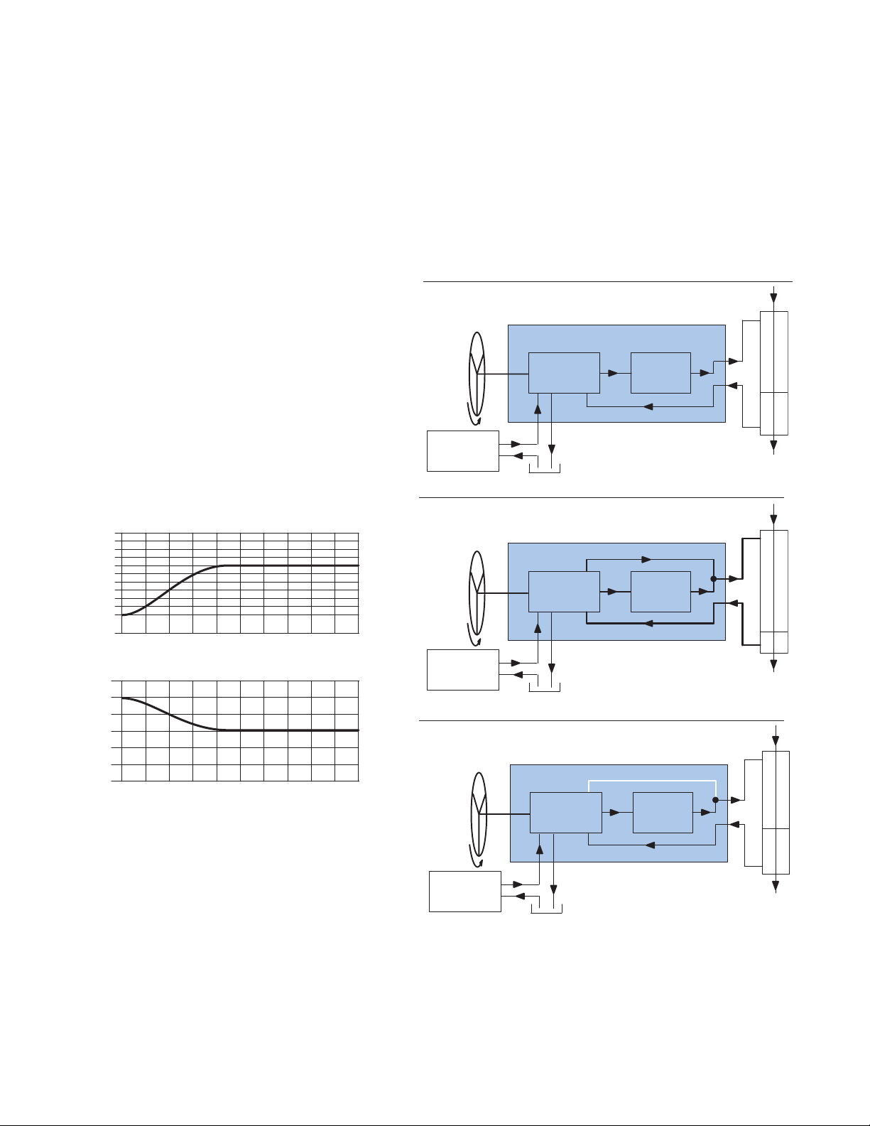
Eaton Patented
Technologies
Q-Amp (Flow
Amplification)
for Load Sensing
Circuits
Description
Q-Amp steering units have
built in variable orifices
that provide flow directly to
the cylinder without going
through the gerotor section.
The orifices do not open
until after the gerotor begins
to rotate and then gradually
open until the desired flow
is achieved which is
proportional to the flow
going through the gerotor. A
typical Q-Amp unit has a
ratio of 1.6 : 1 which means
the flow of the cylinder is
1.6 times the flow going
through the gerotor when
turning the steering wheel
at medium to fast speeds.
(See model code for
available ratios.)
Covered by one or more of the following U.S.
and foreign Patents: 4759182, 4862690,
4781219. Unequal area Q-Amp.
Q-Amp Steering Control Unit—Slow Turn
Features
• Variable Ratio
Q-Amp Steering Control Unit—Fast Turn
Conventional Steering Control Unit
16 EATON Char-Lynn Steering Catalog C-STOV-MC0 01-E1 July 2006
2:1
1.6:1
Ratio
1:1
10 20 30 40 50
6
5
4
Turns
3
Lock
to
2
Lock
1
10
20 30 40 50
60 70 80 90 100
RPM
60 70 80 90 100
RPM
Fast
Turn
Pump
Fast
Turn
Pump
Slow
Turn
Pump
Rotary
Valve
Rotary
Valve
No Flow
Rotary
Valve
Meter
Cylinder
Meter
Cylinder
Meter
Cylinder
Page 17

EATON Char-Lynn Steering Catalog C-STOV-MC001-E1 July 2006 17
Eaton Patented
Technologies
Q-Amp (Flow
Amplification)
for Load Sensing
Circuits
Applications
Articulated vehicles such as
wheel loaders, log skidders,
scrapers, trucks, and similar
vehicles can benefit from
this feature.
While roading, a slow
movement of the steering
wheel (input speed), will not
overcorrect steering.
Increasing input speed will
produce the additional
steering flow required to
quickly change the vehicle’s
direction.
For example, operating log
skidders in the woods
requires very quick steering.
This same log skidder on
the road would be extremely
difficult to steer a straight
normal course. The variable
ratio feature provides good
steering in both conditions.
Combines, row crop tractors,
and large articulated
agricultural tractors also can
benefit from this feature
when traveling down
a field. It will be easier to
follow rows or furrows, and
still be able to make fast
turns at the end of the rows.
Variable Ratio
• Wheel Loaders
• Scrapers
• Articulated AG Tractors
• Articulated Dumpers
• Mine T ruc ks
• Forestry Equipment
• Rough T errain Lift T r ucks
Variable Ratio with
Manual Steering
• AG T ractors
• Small Wheel Loaders
• Rubber Tired Excavators
• Sprayers
• Site Handlers
• Graders
• Combines
Page 18
18 EATON Char-Lynn Steering Catalog C-STOV-MC0 01-E1 July 2006
Eaton Patented
Technologies
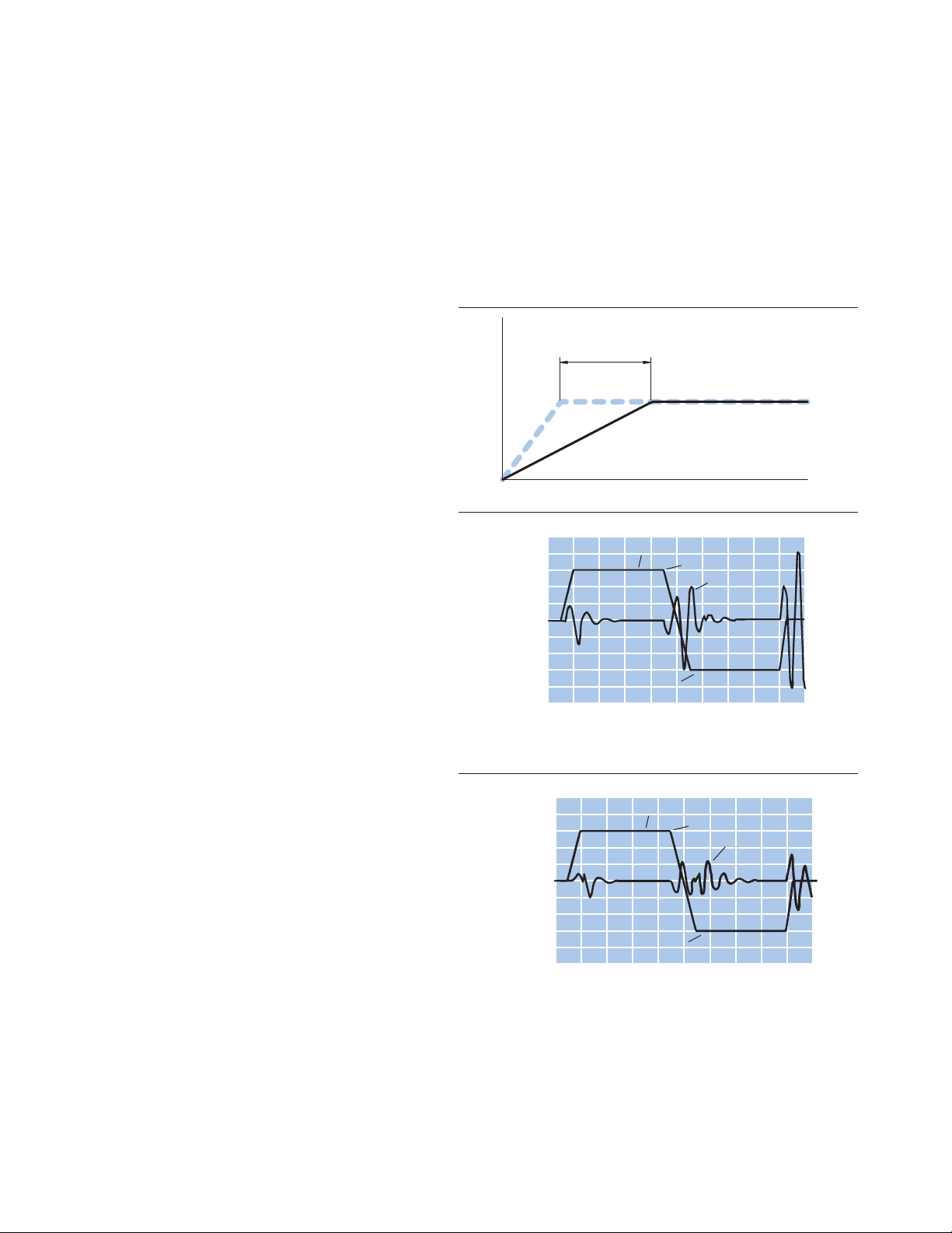
Wide Angle
Description
Steering units with wide
angle features have been
developed to significantly
reduce or eliminate the jerky
motion of vehicles with
articulated steering systems.
This has been accomplished
by increasing the maximum
deflection of the spool
relative to the
sleeve. Increasing the
deflection reduces the gain.
This in turn reduces
acceleration and jerk levels
and provides overall
smoother vehicle
performance. The steering
still responds fast enough so
the operator does not notice
the reduced gain.
Benefits
• Minimizes jerking
motion on medium and
large articulated
vehicles.
• Jerk reducing valves and
accumulators can be
eliminated on most
vehicles.
• Avaliable on Series 10,
Series 20 (standard),
and Series 25.
• Eliminates need for
cushion valves
Applications
• Articulated Vehicles
Wide Angle Steering Control Units Patent No. 5080135
These graphs show a computer simulation of the jerk levels and have been verified by
actual vehicle tests.
Flow
60 RPM
125 ms
Wide Angle
Standard
Time
Jerk (g/sec)
8
4
0
-4
-8
012346
Steering Input (RPM)
60 RPM CCW
Time (Seconds)
Standard Steering on a 25 Ton Loader
Computer Simulation
60 RPM CW
Jerk (g/sec)
Jerk (g/sec)
8
4
0
-4
-8
012346
Steering Input (RPM)
60 RPM CW
Jerk (g/sec)
60 RPM CCW
Time (Seconds)
Wide Angle Steering on a 25 Ton Loader
Page 19
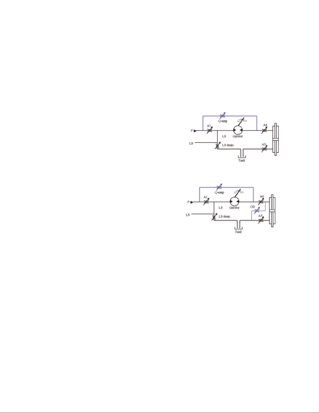
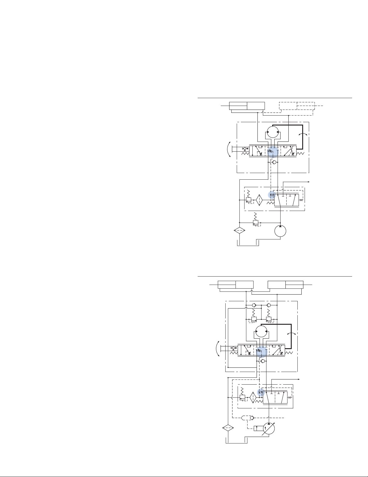
Eaton Patented
Technologies
Cylinder Damping
Description
Cylinder damping can help
smooth the steering action
of large articulated vehicles
such as loaders, scrapers,
and skidders. These vehicles
have overhanging weight
with high inertial loads. This
energy is dissipated by the
cylinder damping orifices
which bleed a small amount
of flow from the cylinder
port to tank.
Cylinder Damping has 3
different levels of
application. The number of
levels equal to the number
of Cylinder Damping (CD)
orifices. This technology is
available on Series 10,
Series 20, Series 25, and
Series 40. Not all SCUs
come with all 3 levels.
Features
Three levels engineered to
fit your application.
Benefits
• Reduces jerking motion
on medium and large
articulated vehicles.
• Available on the
following steering
control units (Series 10,
20, 25, 40).
• Damps or stabilizes
unstable systems.
Applications—
Large Articulated Vehicles
• Wheel Loaders
• Skidders
• Scrapers
Flow Amplification without Cylinder Damping
Flow Amplification with Cylinder Damping
Steering Control Units with Cylinder Damping
Patent No. 5080135
EATON Char-Lynn Steering Catalog C-STOV-MC001-E1 July 2006 19
Page 20

20 EATON Char-Lynn Steering Catalog C-STOV-MC0 01-E1 July 2006
Eaton Patented
Technologies
VersaSteer
Description
Eaton’s patented
VersaSteer™ technology
offers operator-selectable
Metered or Quick Steering
modes at any time, with the
touch of a button or the flip
of a switch, and provides
the operator flexibility to
significantly improve the
overall steering experience.
Dual Steering Modes
Metered Steering –The
steering unit operates the
same as a traditional
hydrostatic steering control
unit. Steering (flow) is a
function of steering wheel
rotations (rpm). Metered
(gerotor) steering provides
precise, responsive, and
smooth steering.
Quick Steering –
Gerotorless (quick) steering
provides a much different
effect, enabling the operator
to put the vehicle in full lock
while only turning the
steering wheel a few
degrees. This is achieved by
hydraulically blocking the
flow of oil to the gerotor
with a shift valve. Full
steering flow can be
obtained by deflecting the
steering wheel ±45° for a
Series 10 and ±50° for a
Series 20. Operator effort is
greatly reduced during the
work cycle.
Benefits
• Provides steering
system cost savings by
eliminating the need for
a separate joystick
• Available on Load Sense
steering systems
• Compatible with
Integral Valv es, Bolt-On
Priority Valv es, Q-Amp
and Cylinder Damping
• Emergency manual
steering capability
• Minor size increase –
can retrofit to existing
vehicles
• Smoother steering with
Eaton Patented W ide
Angle technology.
Features
• Dual steering modes in
one integrated Steering
Control Unit (SCU)
• High pressure rating
and flow capabilities
• Compatible with current
steering options
• Easily retrofit to existing
vehicles
• Proven base technology
• Easy one-touch switch
(OEM defined)
VersaSteer System
Components
• Steering Control Unit
• Solenoid Shift Valve
• Four –04 hoses
• Electric Switch
Series 10 VersaSteer
Traditional Metered Steering Series 10 Quick Steering
Series 20 VersaSteer
SPECIFICATIONS
1. System Pressure Rating a. 241 Bar [3500 psi] - Series 10
b. 241 Bar [3500 psi] - Series 20
2. Back Pressure Rating - 21 Bar [305 psi]
3. Flow Rating
a. 15 gpm - Series 10
b. 25 gpm - Series 20
VersaSteer is covered under
US Patent No. 6,318,078
Page 21

EATON Char-Lynn Steering Catalog C-STOV-MC001-E1 July 2006 21
Eaton Patented
Technologies
STC Direct Porting
With the Snap-To-Connect
(STC) Direct Porting option,
the fitting profile is
machined into the SCU
housing, eliminating the
need for extra STC fittings.
This revolutionary and
patented porting technology
provides leak-proof sealing
and has operating pressure
capability exceeding
4500PSI (310bar).
STC Direct Porting is
available with Series 5 and
Series 10 Steering Control
Units.
Benefits
• STC Direct Ports
provide a great
opportunity for
significant cost savings
compared to threaded
fittings
• Eliminates the need for
assembly tools during
installation
• Eliminates installation
variability
• Improves ergonomics reduces installer effort
to connect
• Improves serviceability
• High quality, leak-proof
seal
• Eliminates connector
leakage
• Compact design and
overall lighter weight
Page 22

22 EATON Steering Catalog C-STOV-MC0 01-E1 May 2006
Steering Control
Units—Series 5
Product
Description
The new Series 5 steering
control units (SCU) are
exciting new products
designed for low flow, low
pressure applications.
The Series 5 units are
available in two compact
designs:
Option 1:
Square Housing (Mount)
Unit with Side Ports
Option 2:
Round Housing (Mount) Unit
with End Ports
In addition to the installation
flexibility provided by the
two options above, this new
family of products has bestin-class steering feel and
provides crisp centering.
These units also have better
efficiency (lower pressure
drop) than competitive units.
Power Beyond Models—
Optional power beyond
steering control units supply
steering and flow to auxiliary
valve functions. The power
beyond unit is used in open
center (fixed displacement
pump) systems in the
medium pressure range.
When not steering, the
power beyond unit directs all
inlet flow to the excess flow
port (power beyond) for use
in the auxiliary circuit. Once
steering is initiated, and
since steering has priority,
inlet flow will be diverted to
the steering circuit as
required. Flow out the
excess flow port (power
beyond) and tank port will
vary or stop depending upon
the steering requirement.
The tank port of the steering
unit has flow only when
steering is operating.
SPECIFICATIONS
Max. System Pressure 140 bar [2030 PSI]
Max. Back Pressure 21 bar [ 300 PSI]
Max. Flow 19 l/min [5 GPM]
Max. Differential
Between Steering Unit 28°C
and System Temperature 50°F
Max. System Operating Temperature 93°C [200° F]
Input Torque
Powered -Standard 1,7 - 2,8 Nm @ 6,9 bar tank pressure
[15 - 25 lb-in @ 100 PSI tank pressure]
Low 1,1 - 2,0 Nm @ 6,9 bar tank pressure
[10 - 17.5 lb-in @ 100 PSI tank pressure]
Max. Non Powered 81,4 Nm [60 lb-ft]
Fluid Petroleum Based Fluids
Recommended Filtration ISO 18/13 cleanliness level
Port Options 9/16-18 SAE O-ring
– 06 STC
3/8 BSP Straight thread ports
Check Valve for Manual Steering Yes
Optional Relief Valve Settings
bar [PSI] 40 [ 580]
50 [ 725]
63 [ 914]
70 [1015]
80 [1160]
90 [1305]
100 [1450]
125 [1812]
Option 1: Square Housing
with Side Ports
refer to Model Code, page 23
Option 2: Round Housing
with End Ports
refer to Model Code, page 24
Features
• Open Center
• Load Sensing
• Open Center
Power Beyond
• Integral Column
• Manual Steering
Check V alv e
• Inlet Relief Valve
• Load Sense Relief Valve
• Cylinder Relief Valve
• Anti-Cavitation Valve
Applications
• Lawn and Garden
Equipment
• T urf Equipment
• Golf Course
Maintenance
Equipment
• Lift Trucks
• Compact Utility Tractors
Page 23
EATON Steering Catalog C-STOV-MC001-E1 May 2006 23
Steering Control
Units—Series 5
Model Code –
Ordering
Information
The following 30-digit coding system has been developed to
identify all of the configuration options for the Series 5
steering control units. Use this model code to specify a unit
with the desired features. All 30-digits of the code must be
present when ordering. You may want to photocopy the
matrix below to ensure that each number is entered in the
correct box.
Nos Feature Code Description Nos Feature Code Description
1,2,3 Product Series ABR Series 5 Steering Control Unit
4 Nominal Flow 1 11 l/min [3 GPM]
Rating B 19 l/min [5 GPM]
5 Inlet Pressure C 140 bar [2030 PSI]
Rating
6 Tank Pressure A 10 bar [150 PSI]
Rating B 21 bar [30 0 PSI]
7-8 Displacement 35 31.5 cm3/r [1.92 in3/r]
37 39.5 cm3/r [2.41 in3/r]
39 50.8 cm3/r [3.10 in3/r]
41 63.1 cm3/r [3.85 in3/r]
43 73.8 cm3/r [4.50 in3/r]
46 100 cm3/r [6.10 in3/r]
48 120 cm3/r [7.33 in3/r]
9 Flow Amplification 0 None
10 Neutral Circuit A Open Center
B Open Center, Power Beyond
F Load Sensing, Dynamic signal
11 Load Circuit A Non-Load Reaction
12,13 Valve Options 01 Manual Steering Check Valve
04 Inlet Check Valve, Manual
Steering Check Valve
05 Inlet Relief Valve,
Manual Steering Check Valve
12 Cylinder Relief Valve,
Anti-Cavitation Valve,
Inlet Relief Valve,
Inlet Check Valve,
Manual Steering Check Valve.
13 Cylinder Relief Valve,
Anti-cavitation Valve, Inlet Check
Valve, Load Sensing Relief Valve,
Manual Steering Check Valve
14,15 Integral Inlet 0 0 None
Relief Valve 18 40 bar [580 PSI]
Setting 1J 50 bar [725 PSI]
1Z 63 bar [914 PSI]
26 70 bar [1015 PSI]
2G 80 bar [1160 PSI]
2T 90 bar [1305 PSI]
34 100 bar [1450 PSI]
3W 125 bar [1812 PSI]
16,17 Cylinder Relief 00 None
Setting 37 103 bar [1490 PSI]
42 130 bar [1890 PSI]
55 185 bar [2680 PSI]
68 200 bar [2900 PSI]
18,1 9,20,21 Ports and 4AAN Square 4 x 9/16 SAE Ports,
Mounting Threads M10 x 1,5 Column Mounting
Threads (Use with Open Center)
4AKN Square 5 x 9/16 SAE Ports,
M10 x 1,5 Column Mounting
Threads (Use with Excess Flow)
4AEN Square 5 x 9/16 SAE Ports,
M10 x 1,5 Column Mounting
Threads (Use with Load Sense)
UAAN Square 4 x -06 STC Direct
Ports, M10 x 1,5 Column
Mounting Threads (Use with
Open Center)
UBNN Square 5 x -06 STC Direct
Ports, M10 x 1,5 Column
Mounting Threads
(Use with Excess Flow)
UBPN Square 5 x -06 STC Direct
Ports, M10 x 1,5 Column
Mounting Threads
(Use with Load Sense)
YAAN Square 4 x G .375 BSP Striaght
Thd. Ports, M10 x 1,5 Column
Mounting Threads
(Use with Open Center)
YBRN Square 5 x G .375 BSP Striaght
Thd. Ports, M10 x 1,5 Column
Mounting Threads
(Use with Load Sense)
22 Input Torque 1 Low*
3 Standard
23 Fluid Type A See Eaton Tec hnical
Bulletin 3-401
24 Special Application 0 None
25,26 Special Feature AA None
27 Paint 1 Black Primer
28 Identification 0 Eaton Product Number on
Nameplate
29 Mechanical A Tapered 17.919mm (.7055in)
Interface diameter, .083:1 and serrated
17.5 (.688) diameter, 40 tooth,
M16x1.5-6g, Extension length
65.02 (2.56)
D Internal involute spline12 tooth,
16/32 DP, 30 degree PA
30 Eaton Assigned B Assigned Design Code
Design Code
* All low torque units need approval from an Eaton Steering Engineer.
Square Housing with Side Ports - Option 1
1 2 3 4 5 6 7 8 9 10 11 12 13 14 15 16 17 18 19 20 21 22 23 24 25 26 27 28 29 30
A B R 0 A A 0 1 0 B
C A
Page 24
24 EATON Char-Lynn Steering Catalog C-STOV-MC001-E1 July 2006
Steering Control
Units—Series 5
Model Code –
Ordering
Information
The following 30-digit coding system has been developed to
identify all of the configuration options for the Series 5 steering
control units. Use this model code to specify a unit with the
desired features. All 30-digits of the code must be present when
ordering. You may want to photocopy the matrix below to ensure
that each number is entered in the correct box.
Nos Feature Code Description Nos Feature Code Description
1,2,3 Product Series ABR Series 5 Steering Control Unit
4 Nominal Flow 1 11 l/min [3 GPM]
Rating B 19 l/min [5 GPM]
5 Inlet Pressure
Rating C 140 bar [2030 PSI]
6 Tank Pressure A 10 bar [150 PSI]
Rating
7-8 Displacement 35 31.5 cm3/r [1.92 in3/r]
37 39.5 cm3/r [2.41 in3/r]
39 50.8 cm3/r [3.10 in3/r]
41 63.1 cm3/r [3.85 in3/r]
43 73.8 cm3/r [4.50 in3/r]
46 100 cm3/r [6.10 in3/r]
48 120 cm3/r [7.33 in3/r]
9 Flow Amplification 0 None
10 Neutral Circuit A Open Center
B Open Center, Power Beyond
C Closed Center
F Load Sensing, Dynamic signal
11 Load Circuit A Non-Load Reaction
12,13 Valve Options 01 Manual Steering Check Valve
04 Inlet Check Valve, Manual
Steering Check Valve
05 Inlet Relief Valve,
Manual Steering Check Valve
12 Cylinder Relief Valve,
Anti-cavitation Valve,
Inlet Relief Valve,
Inlet Check Valve,
Manual Steering Check Valve.
14,15 Integral Inlet 0 0 None
Relief Valve 18 40 bar [580 PSI]
Setting 1J 50 bar [725 PSI]
1Z 63 bar [914 PSI]
26 70 bar [1020 PSI]
2G 80 bar [1160 PSI]
2T 90 bar [1310 PSI]
34 100 bar [1450 PSI]
3W 125 bar [1812 PSI]
4C 140 Bar [2030 PSI]
16,17 Cylinder Relief 00 None
Setting
18,1 9,20,21 Ports and VAAH Round 4 x 9/16 SAE Ports,
Mounting Threads M6 x 1,0 Column Mounting
Threads (Use with Open Center)
VAKH Round 5 x 9/16 SAE Ports,
M6 x 1,0 Column Mounting
Threads (Use with Excess Flow)
VAEH Round 5 x 9/16 SAE Ports,
M6 x 1,0 Column Mounting
WAAH Round 4 x -06 STC Direct Ports,
M6 x 1,0 Column Mounting
Threads (Use with Open Center)
WBNH Round 5 x -06 STC Direct Ports,
M6 x 1,0 Column Mounting
Threads (Use with Excess Flow)
WBPH Round 5 x -06 STC Direct Ports,
M6 x 1,0 Column Mounting
Threads (Use with Load Sense)
22 Input Torque 1 Low*
3 Standard
23 Fluid Type A See Eaton Tec hnical
Bulletin 3-401
24 Special Application 0 None
25,26 Special Feature AA None
27 Paint 1 Black Primer
28 Identification 0 Eaton Product Number on
Nameplate
29 Mechanical A Tapered 17.919mm (.7055in)
Interface diameter, .083:1 and serrated
17.5 (.688) diameter, 40 tooth,
M16x1.5-6g, Extension length
65.02 (2.56)
D Internal involute spline12 tooth,
16/32 DP, 30 degree PA
30 Eaton Assigned B Assigned Design Code
Design Code
* All low torque units need approval from an Eaton Steering Engineer.
** Plug-O ports rated to 103 bar [1500PSI]
Round Housing with End Ports - Option 2
1 2 3 4 5 6 7 8 9 10 11 12 13 14 15 16 17 18 19 20 21 22 23 24 25 26 27 28 29 30
A B R 0 A 0 0 A 0 1 0 B
A
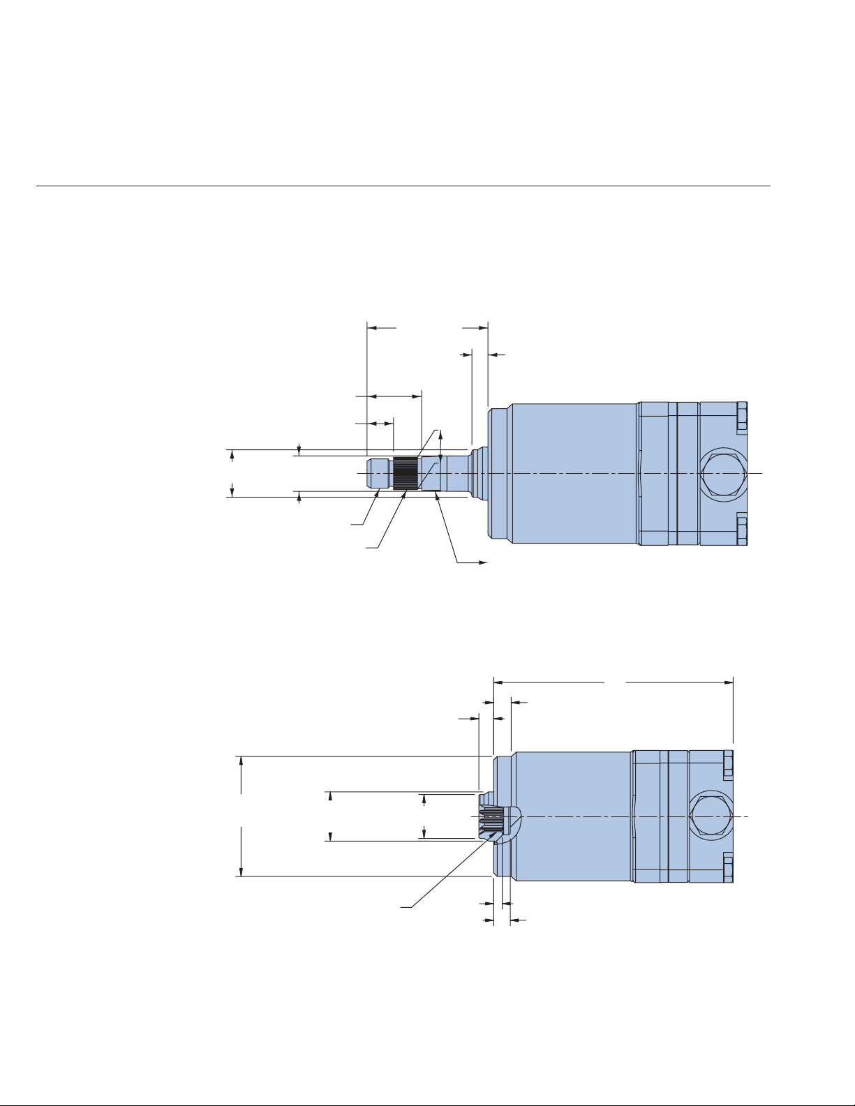
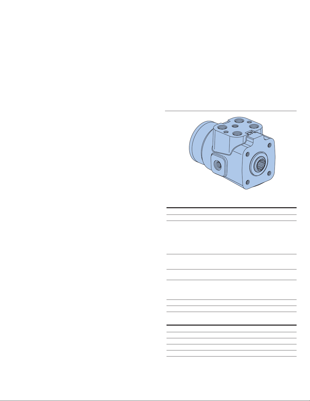
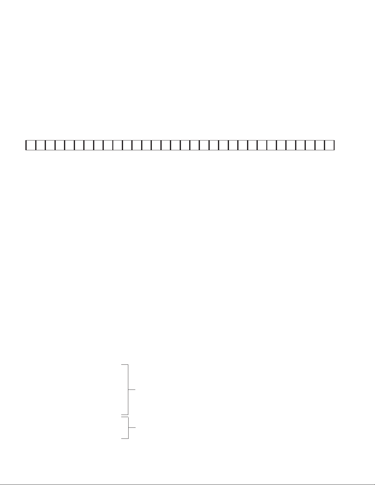
Page 25
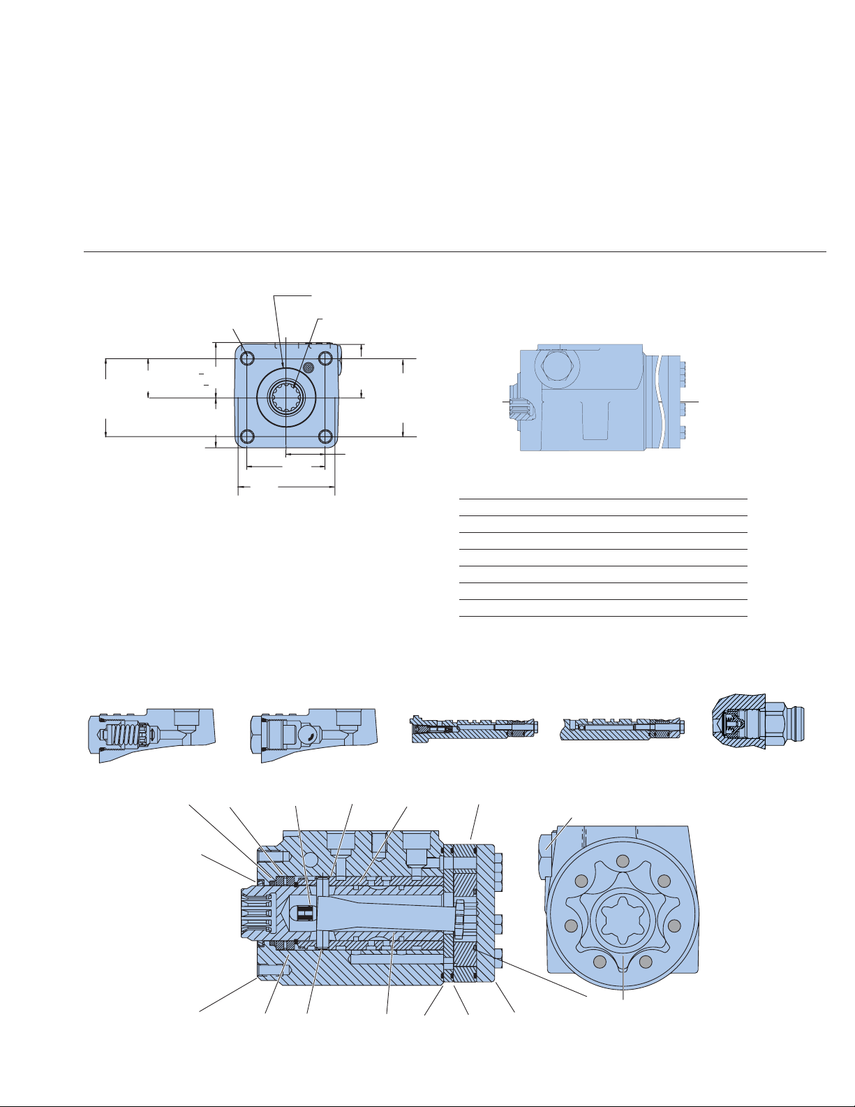
Option 1: Square Housing with Side Ports
refer to Model Code, page 23
Steering Control
Units—Series 5
Installation
Drawing
Relief Valve/Check
or Manual Check
Relief Valve/Check Manual Check
View of Gerotor Section
Gerotor Seal
Cylinder Relief Valve Anti-Cavitation Valve
Inlet Check Valve
Housing
PinBearing, Ball Drive Spacer Plate End Cap
O-ring
Bearing
Race
Shaft
Seal
Dust Seal
Centering Springs Sleeve Spool Gerotor
Sectional Drawing
EATON Steering Catalog C-STOV-MC001-E1 May 2006 25
Side View
Displacement Dim. A Max.
Code cm3/r [in3/r] mm [inch]
35 31.5 [1.92] 123.4 [4.86]
37 39.5 [2.41] 125.2 [4.93]
39 50.8 [3.10] 124.2 [4.89]
41 63.1 [3.85] 126.2 [4.97]
43 73.8 [4.50] 128.0 [5.04]
46 100.0 [6.10] 132.3 [5.21]
48 120.0 [7.33] 135.4 [5.33]
4X M10 x 1.5-6H
15,2 [.60] Min
44,4 [1.75] Dia.
Involute Spline
12 Tooth 16/32 D.P.
30° P.A. PER SPC DS-023-2
48.26+0.13
29,18
58.37
[1.149]
[1.900+.005]
[2.298]
38,4
[1.51]MAX
58,37
[2.298]
78,5
[3.09]MAX
40,6
[1.60] MAX
58,37
[2.298]
29,18
[1.149]
Page 26
26 EATON Char-Lynn Steering Catalog C-STOV-MC001-E1 July 2006
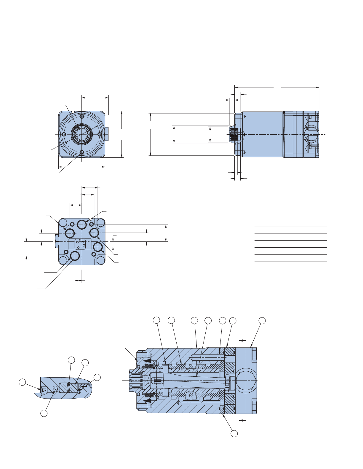
Option 3: Square Housing with End Ports
refer to Model Code, page 24
Steering Control
Units—Series 5
Installation
Drawing
Option 2: Round Housing with End Ports
Sectional Drawing
11 Pin
10 Sleeve
8 Drive
3 O-ring
5 Gerotor
2 End cap
22 Dust seal
16 Bearing
15 Race
21 Quad seal
23 Retaining ring
7 Wear plate
6 housing
Displacement Dim. A Max.
cm3/r [in3/r] mm [inch]
31.5 [1.92] 135.1 [5.32]
39.5 [2.41] 137.2 [5.40]
50.8 [3.10] 136.1 [5.36]
63.1 [3.85] 137.9 [5.43]
73.8 [4.50] 139.7 [5.50]
100 [6.10] 144 [5.67]
120 [7.33] 147.3 [5.80]
Involute Spline
12 Tooth 16/32 D.P.
30° P.A.
59,00
[2.323] Dia.
[3.17] MAX
4 x M6 x 1.0-6H
12,2 [.48] Min. Depth
20,3±0,5
[.80±.02]
19,8±0,5
[.78±.02]
Pressure Port
13,7±0,5
[.54±.02]
23,6±0,5
[.93±.02]
5X .5625-18
UNF-2B SAE
O-Ring Port
Left Port
[1.75] MAX
80,5
11,4±0,5
[.45±.02]
44,4
26,4±0,5
[1.04±.02]
[2.750±.002] Dia.
80,5
[3.17] MAX
Additional Port
8,9±0,5
[.35±.02]
Right Port
Tank Port
69,85±0,05
[.57±.02]
14,5±0,5
28,6
[1.126] MAX Dia.
27,9±0,5
[1.10±.02]
9,1
[.36] MAX
25,7
[1.01] MAX Dia.
5,1±0.8
[.20±.03]
A
9,9
[.39] MIN
8,9
[.35] MIN
11
10
VIEW B
16
15
22
23
D
D
VIEW B
21
6
3
8
5
C
C
7
2
Page 27
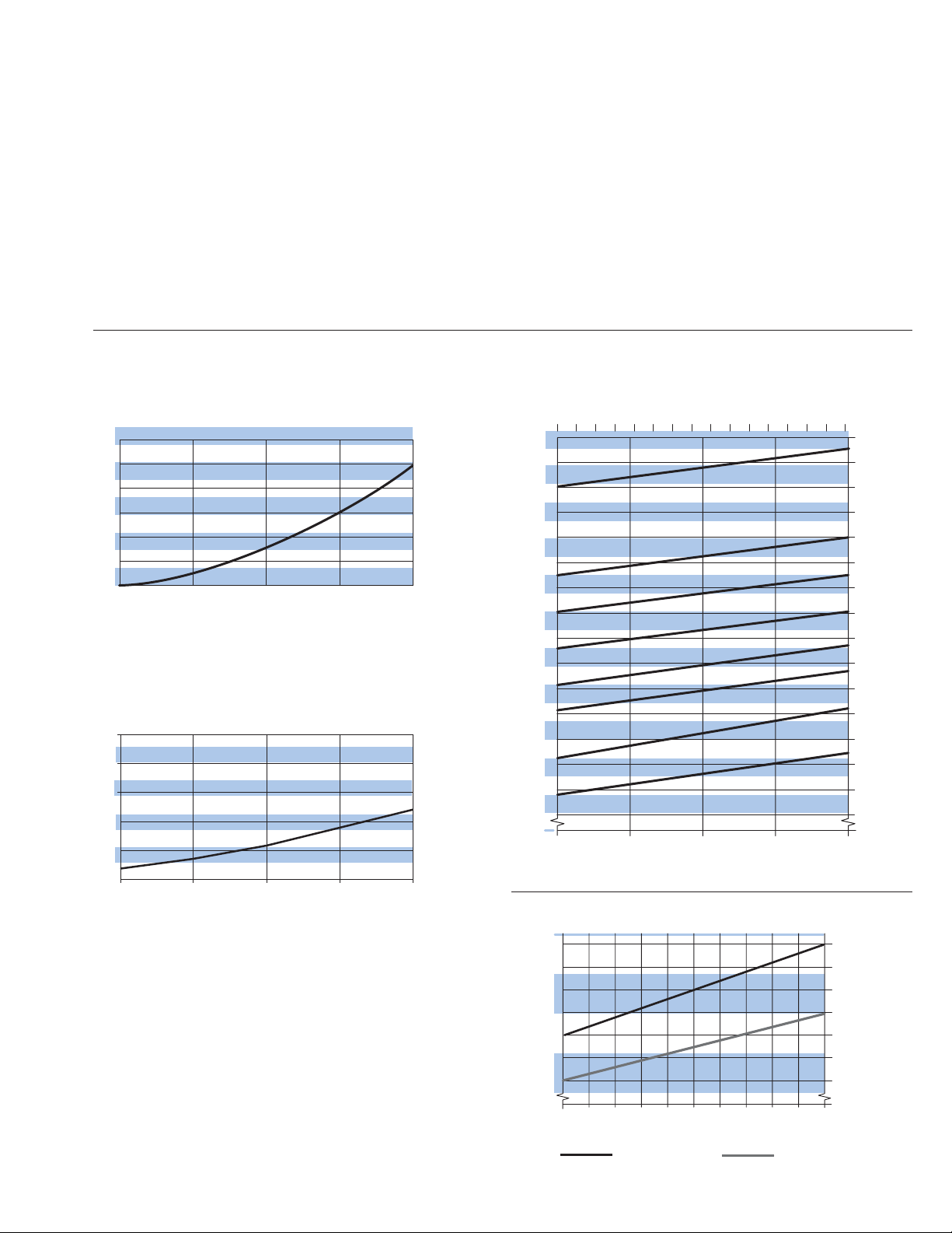
EATON Steering Catalog C-STOV-MC001-E1 May 2006 27
Steering Control
Units—Series 5
Performance Data
Neutral Pressure Drop
Inlet to Auxiliary
Relief V alve Curve
Input T orque Curve
bar
8
6
4
2
0
0
bar
14
10
6
2
8
[2]
11 L/min [3 GPM] Rated Round Unit
4
[1]
19 L/Min (5 GPM) Rated Unit
11
[3]
7
[2]
L/min [GPM]
15
[4]
L/min [GPM]
11
[3]
19
[5]
23
[6]
15
[4]
[PSI]
[120]
[ 80]
[ 40]
[ 0]
[PSI]
[250]
[200]
[150]
[100]
[ 50]
[ 0]
1 3 5 7 9 11 13 15
135
125
115
105
95
85
bar
75
65
55
45
35
0
0
3
L/min
2000
1900
1800
1700
1600
1500
1400
1300
1200
PSI
1100
1000
900
800
700
600
500
1234
GPM
0
25
20
2
1
0 102030405060708090100
Percent Deflection
Standard torque
Low torque
in-lbNm
15
10
Page 28
28 EATON Char-Lynn Steering Catalog C-STOV-MC001-E1 July 2006
Tapered 17.919mm (.7055in)
diameter, .083:1 and serrated
17.5 (.688) diameter, 40 tooth,
M16x1.5-6g, Extension length
65.02 (2.56)
M16 x 1.5-6g
.0831:1
65.0 ± 0.5
[2.56 ± .02]
9.1
[.36] MAX
25.7
[1.01] MAX
19.2
[.755] MAX
14.27 ± 0.25
[.562 ± .010]
29.36 ± 0.25
[1.156 ± .010]
17.919
[.7055]
Steering Control
Units—Series 5
Integral Column
Option
Integral Column
Option Av ailable in
Square Housing with
Side Ports, and Round
Housing with End
Ports
40 T ooth Serrated Integral
Column Option (Shown on
Round Housing with End
Ports)
12 Tooth Internal Spline
Standard Mechanical Interface
(Shown on Round Housing
with End Ports)
69,85±0,05
[2.750±.002] Dia.
28,6
[1.126] MAX Dia.
Internal Involute Spline
12 Tooth 16/32 D.P.
30° P.A.
9,1
[.36] MAX
25,7
[1.01] MAX Dia.
5,1±0,8
[.20±.03]
A
9,9
[.39] MIN
8,9
[.35] MIN
Page 29
Steering Control
Units—Series 10
Product Description
Eaton’s Series 10 Steering
Control Unit (SCU) facilitates
hydraulic fluid flow like no
other unit on the market.
This highly-engineered product
is the ultimate SCU for
mid-range flow applications.
Benefits
• The new Series 10 SCU
has an unprecedented,
continuous pressure
rating of 275 bar (4000
psi), making it ideal for
heavy-duty equipment,
such as construction
and agricultural
machinery.
• Its high-pressure
rating reduces overall
equipment costs, since
smaller cylinder sizes
can be assigned into
the system.
• The new Series 10
incorporates proven
Eaton technologies. An
internal, balanced
architecture and a widewalled sleeve that is
40% thicker than
standard designs offer
increased performance
during transient
pressure conditions.
Features
• Open Center
• Power Beyond
• Closed Center
• Load Sensing
• Integral Valves
• Q-Amp
• 2-Speed
• Dual Displacement
• V ersa Steer
• Wide Angle
• Cylinder Damping
Applications
• Construction Machinery
• Agriculture Machinery
• Heavy-Duty Equipment
• Marine
• Forestry Machinery
• Mining Equipment
SPECIFICATIONS
Max. System Pressure 275 bar [4000 PSI]
Max. Back Pressure 21 bar [305 PSI]
Rated Flow
– Low 7,6 - 15 l/min [ 2 - 4 GPM]
– Medium 15 - 30 l/min [ 4 - 8 GPM]
– High 30 - 61 l/min [ 8 - 16 GPM]
– Low (with Q-Amp) 8 - 19 l/min [ 2 - 5 GPM]
– Medium (with Q-Amp) 19 - 38 l/min [ 5 - 10 GPM]
– High (with Q-Amp) 38 - 76 l/min [10 - 20 GPM]
Max. Differential
Between Steering Unit
and System Temperature 28° C [50° F]
Max. System
Operating Temperature 93°C [200° F]
Input Torque
Powered 1,1-2,8 Nm @ 6,9 bar back pressure
[10-25 lb-in @ 100 PSI back pressure]
Non-Powered 136 Nm [100 lb-ft]
Fluid See Eaton Technical Bulletin 3-401
Recommended Filtration ISO 18/13 cleanliness level
PORT SIZES:
Work Ports (4) Load Sense (LS) Port (1)*
3/4-16 (SAE) 7/16-20
M18 x 1,5 - 6H M12 x 1,5 - 6H
G 1/2 (BSP) Straight Thread G 1/4 (BSP) Straight Thread
STC Dash 08** STC Dash 06**
*Top or side when applicable
**STC
®
Ports, Aeroquip patented, feature snap to connect technology
EATON Steering Catalog C-STOV-MC001-E1 May 2006 29
Page 30
Steering Control
1 2 3 4 5 6 7 8 9 10 11 12 13 14 15 16 17 18 19 20 21 22 23 24 25 26 27 28 29
30 31 32
A D R AAAAA01AA
Model Code — Series 10 Steering Control Units
Units—Series 10
Model Code—
Ordering
Information
The following 32-digit coding system has been developed to
identify all of the configuration options for the Series 10
steering control units. Use this model code to specify a unit
with the desired features. All 32-digits of the code must be
present when ordering. You may want to photocopy the
matrix below to ensure that each number is entered in the
correct box.
Nos Feature Code Description Nos Feature Code Description
1,2,3 Product Series ADR Series 10 Steering Control
4 Unit Type A Standard
5 Nominal Flow Rating 1 11 l/min [3 GPM]
6 Inlet Pressure Rating 1 276 bar [4000 PSI]—(Load
7 Return Pressure A 21 bar [305 PSI] Max.—
Rating (standard rating*)
8-9 Displacement 01 352 [21.5] / 60 [3.6]
cm3/r [in3/r] — 02 218 [13.3] / 60 [3.6]
Dual Displacement 03 290 [17.7] / 60 [ 3.6]
Combined/Manual 04 440 [26.8] / 146 [8.9]
8-9 Displacement 40 60 [3.6]
cm3/r [in3/r] 43 75 [4.5]
Unit
B Dual Displacement
C Wide Angle
D 2-Speed
E 2-Speed with Wide Angle
G Dual Displacement with Wide
Angle
V Versa Steer, Wide Angle
(Open Center)
2 23 l/min [6 GPM]
(Closed Center and LS)
3 45 l/min [12 GPM]
(OC, CC, and LS)
4 19 l/min [5 GPM]
(Q-Amp)
5 38 l/min [10 GPM]
(Q-Amp)
6 76 l/min [20 GPM]
(Q-Amp)
7 23 l/min [6 GPM]
(Open Center)
sensing and closed center)
2 207 bar [3000 PSI]—
(Open center)
B 10 bar [145 PSI] Max.
05 231 [14.1] / 85 [5.2]
45 95 [5.9]
48 120 [7.3]
50 145 [8.9]
51 160 [9.7]
52 185 [11.3]
54 230 [14.1]
57 295 [17.9]
59 370 [22.6]
61 460 [28.2]
64 590 [35.9]
66 740 [45.1]
1-8 GPM
8-16 GPM
10 Flow Amplification** A None (No Q-Amp)
B 1.6 : 1.0 Ratio†
C 1.6 : 1.0 Ratio
(with Manual Steering)†
E 2.0 : 1.0 Ratio
(with Manual Steering)†
G 1.3 : 1.0 Ratio
(with Manual Steering)†
†Use with closed center or
load sensing only.
11 Neutral Circuit A Open Center
C Closed Center
D Load Sensing, Static Signal
E Load Sensing, Dynamic Signal
F Open center with
Power Beyond
12 Load Circuit A Non-Load Reaction
B Load Reaction (Open Center
3,8 - 30 l/min [1 - 8 GPM] Only
D Non-Load Reaction,
Cylinder Damped
13,14 Special Spool/Sleeve 00 None
Modification
15,16 Valve Options
Manual Load Inlet Cylinder Anti- Inlet
Steering Sensing Check Relief Cavitation Relief
Check Relief Valve Valve Valve Valve
01 •
02 • •
03 • •
04 • • •
05 • •
06 • • •
07 • • •
08 • • • •
09 • • • • •
10• ••• •
11 • • •
* 12 GPM open center requires 145psi back pressure
** All Q-amp applications need approval from an Eaton Applications Engineer
30 EATON Char-Lynn Steering Catalog C-STOV-MC0 01-E1 July 2006
Continued on next page
Page 31

EATON Steering Catalog C-STOV-MC001-E1 May 2006 31
Steering Control
Units—Series 10
Model Code—
Ordering
Information—
Continued
17 ,18 Inlet or Load Sense 00 None
Relief Valv e — 18 124 [1800]
bar [PSI] 19 131 [1900]
20 138 [2000]
21 145 [2100]
22 152 [2200]
23 158 [2290]
24 165 [2390]
25 172 [2490]
26 179 [2600]
27 186 [2700]
28 193 [2800]
29 200 [2900]
30 207 [3000]
31 214 [3100]
32 220 [3190]
33 227 [3290]
34 234 [3390]
35 241 [3500]
36 248 [3600]
37 255 [3700]
38 262 [3800]
39 269 [3900]
40 276 [4000]
99 136 [1970]
19,20 Cylinder Relief Valve 0 0 None
— bar [PSI] 23 158 [2290]
** Cylinder Relief 24 165 [2390]
setting recommen- 25 172 [2490]
dation is 870 PSI 26 179 [2600]
(60 bar) above 27 186 [2700]
steering inlet/load 28 193 [2800]
sense pressure. 29 200 [2900]
30 207 [3000]
31 214 [3100]
32 220 [3190]
33 227 [3290]
34 234 [3390]]
35 241 [3500]
36 248 [3600]
37 255 [3700]
38 262 [3800]
39 269 [3900]
40 276 [4000]
41 283 [4100]
42 289 [4190]
43 296 [4290]
44 303 [4390
45 310 [4500]
46 317 [4600]
47 324 [4700]
48 331 [4800]
49 338 [4900]
21,22,23,24 Ports and AAAA 4 x 3/4-16 (SAE) Ports
Mounting None (No Additional Port)
Threads 2 x M12 Mounting Threads
Port Face
4 x M10 Mounting Threads
Mounting Face
AABA 4 x 3/4-16 (SAE) Ports
7/16-20 Load Sensing Port on Side
2 x M12 Mounting Threads
Port Face
4 x M10 Mounting Threads
Mounting Face
AACA 4 x 3/4-16 (SAE) Ports
7/16-20 Load Sensing Port Port
Face
2 x M12 Mounting Threads
Port Face
4 x M10 Mounting Threads
Mounting Face
BAAA 4 x M18 x 1,5 - 6H Metric
O-ring Ports
None (No Additional Port)
2 x M12 Mounting Threads
Port Face
4 x M10 Mounting Threads
Mounting Face
BADA 4 x M18 x 1,5 - 6H Metric
O-ring Ports
M12 x 1,5 - 6H Load Sensing Port
on Side
2 x M12 Mounting Threads
Port Face
4 x M10 Mounting Threads
Mounting Face
BAEA 4 x M18 x 1,5 - 6H Metric
O-ring Ports
M12 x 1,5 - 6H Load Sensing Port
Port Face
2 x M12 Mounting Threads
Port Face
4 x M10 Mounting Threads
Mounting Face
CAAA
4 x G 1/2 (BSP) Straight Thread
Ports
None (No Additional Port)
2 x M12 Mounting Threads
Port Face
4 x M10 Mounting Threads
Mounting Face
Continued on next page
Nos Feature Code Description Nos Feature Code Description
Page 32

32 EATON Char-Lynn Steering Catalog C-STOV-MC001-E1 July 2006
21,22,23,24 Ports and CAFA 4 x G 1/2 (BSP) Straight Thread
Mounting Ports
Threads G 1/4 (BSP) LS Straight Thread Port
(continued) on Side
2 x M12 Mounting Threads Port
Face
4 x M10 Mounting Threads
Mounting Face
CAGA 4 x G 1/2 (BSP) Straight Thread
Ports
G 1/4 (BSP) LS Straight Thread Port
on Port Face
2 x M12 Mounting Threads Port
Face
4 x M10 Mounting Threads
Mounting Face
DAAA Dash 08 STC® Ports ***
None (No Additional Port)
2 x M10 Mounting Threads Port
Face
4 x M10 Mounting Threads
Mounting Face
DAHA Dash 08 STC® Ports ***
Dash 06 STC® Port on Side
2 x M10 Mounting Threads Port
Face
4 x M10 Mounting Threads
Mounting Face
DAJA Dash 08 STC® Ports ***
Dash 06 STC® Port Face
2 x M10 Mounting Threads Port
Face
4 x M10 Mounting Threads
Mounting Face
25 Mechanical A Internal Involute Spline,
Interface 12 Tooth 16/32 DP 30° PA
26 Input Torque 3 Standard
27 Fluid Type A See Eaton T echnical
Bulletin 3-401
28,29 Special Features AA None
30 Paints and Packaging 1 Black Primer
31 Identification 0 Eaton Product Number on
Nameplate
32 Eaton Assigned B Assigned Design Code
Design Code
STC®—Aeroquip
Patent numbers: 5,553,895
5,226,682
5,570,910
Steering Control
Units—Series 10
Model Code—
Ordering
Information—
Continued
*** STC with inlet check requires threaded adapter. Contact your Eaton Account Representative for assistance.
Nos Feature Code Description
STC Hose/Connector
Dash 08 Port Face (4)
Dash 06 LS Port Side (1)
STC Port
Release Sleeve
Housing
Retaining Ring
Backup Washer
O-ring
Page 33

EATON Steering Catalog C-STOV-MC001-E1 May 2006 33
PORT AND MOUNTING THREAD COMBINATIONS
Column Load Port
PortMounting Sensing* Mounting
Thread PortThread
3/4 -16 M10 x 1,5-6H 7/16 - 20 M12 x 1,75-6H
M18 x 1,5-6H M10 x 1,5-6H M12 x 1,5-6H M12 x 1,75-6H
STC M10 x 1,5-6H STC M12 x 1,75-6H
G 1/2 (BSP) M10 x 1,5-6H G 1/4 (BSP) M12 x 1,75-6H
*Load Sensing Units Only.
Displacement
cm3/r Dimension C Dimension D
[in3/r] mm [in.] mm [in.]
60 [ 3.6] 10,2 [ .40] 138,1 [5.44]
75 [ 4.5] 10,2 [ .40] 138,1 [5.44]
95 [ 5.9] 13,2 [ .52] 141,1 [5.56]
120 [ 7.3] 16,5 [ .65] 144,4 [5.69]
146 [ 8.9] 20,1 [ .79] 148,0 [5.83]
159 [ 9.7] 21,8 [ .86] 149,9 [5.90]
185 [11.3] 25,4 [1.00] 153,3 [6.04]
231 [14.1] 31,7 [1.25] 159,7 [6.29]
293 [17.9] 40,4 [1.59] 168,3 [6.63]
370 [22.6] 50,8 [2.00] 178,7 [7.04]
462 [28.2] 63,5 [2.50] 191,4 [7.54]
588 [35.9] 80,8 [3.18] 208,8 [8.22]
739 [45.1] 101,6 [4.00] 229,6 [9.04]
Steering Control
Units—Series 10
Installation Drawing
Load Sensing Side Port
44,45/44,34
[1.750/1.746]
Dia.
* LS side port
location changes
with a LSR
83,8
[3.30]
Dia. Max.
8,89/8,39
[.350/.330]
94,0 [3.70] Max.
56,1[2.21]
47,8
2,05/3,36 [.081/.132]
*
8,2 [.32] Max.
[1.88]
37,08/36,32 [1.460/1.430]
63,12/62,62 [2.485/2.465]
48,8
56,13/55,37 [2.210/2.180]
[1.92]
Max.
12 Tooth Involute Spline
16/32 D.P. 30° P.A.
14,2 [.56] Deep
Column Mounting
Thread x 15,2 [.60]
Deep on 82,5 [3.25]
45°
Dia. Bolt Circle
7,4/5,4 [.29/.21] Spline
63,25/62,49
[2.490/2.460]
D
38,61/38,41
[1.52/1.480]
Load Sensing
Side Port
Load Sensing
Port Face
Left
Right
C
44,96/43,94
[1.770/1.730]
22,48/21,98
Tank Pressure
[.885/.865]
Port Mounting Thread x 24,1 [.95] Min. Deep (2)
10,2 [.40] Min. Depth (7,1 [.28] Max.
Mating Spline Depth)
60,51/59,49
[2.382/2.342]
103,6
[4.08]
58,67/58,17
Max.
[2.310/2.290]
45,0/44,0
[1.77/1.73]
Max.
94,0
[3.70]
Max.
83,8
[3.30]
Dia.
Max.
Page 34

34 EATON Char-Lynn Steering Catalog C-STOV-MC001-E1 July 2006
Steering Control
Units—Series 10
Sectional Drawing
and Integral Valves
AA
DD
FF
BB
EE
CC
AA
Inlet Check Valve
DD
Cylinder Port
EE
Anti-Cavitation Valves for Cylinder Ports
Shock Valves
BB
Inlet
Relief
Valve
CC
Internal
Check
Valve for
Limited
Manual
Steering
or
FF
Load
Sense
Relief
Valve
Page 35

EATON Steering Catalog C-STOV-MC001-E1 May 2006 35
Steering Control
Units—Series 10
Performance Data
Cylinder Relief Valve
Pressure Drop versus Flow
Inlet Relief Valve
Pressure Drop versus Flow
Anti-Cavitation V alve
Pressure Drop versus Flow
[1000]
[1500]
[2000]
[2500]
[3000]
[PSI]
bar
Flow GPM
Flow l/min
P1
P2
0510
100
70
130
160
190
220
010203040
**
The examples above are 2 of 24 pressure settings
shown in model code page 30 Position 17, 18
Legend
**
Input T orque
4 6 8 10 12 14 16 18
350
280
210
140
12345
Legend
*
The examples above are 4 of 27 pressure settings shown in
*
model code page 30 Position 19, 20
0246810121416
12
10
8
6
bar
4
2
0
0
12 34
Flow l/min
Flow GPM
P1
(23)
Flow l/min
Flow GPM
P2
(27)
P3
(30)
[5000]
[4000]
[3000]
[2000]
[150]
[100]
[ 50]
[ 0]
[PSI]bar
[PSI]
P4
(34)
3
2
Nm
1
0
0 102030405060708090100
Percent Deflection
Standard Torque
32
28
24
20
16
lb-in
12
8
4
0
Page 36

36 EATON Char-Lynn Steering Catalog C-STOV-MC001-E1 July 2006
Steering Control
Units—
Series 10 Dual
Displacement
Installation
Drawing
Manual
Displacement Dimension C
cm3/r [in3/r] mm [in.]
Gerotor 1
60 [ 3.6] 10,2 [ .40]
60 [ 3.6] 10,2 [ .40]
60 [ 3.6] 10,2 [ .40]
60 [ 3.6] 10,2 [ .40]
60 [ 3.6] 10,2 [ .40]
Displacement Dimension D
cm3/r [in3/r] mm [in.]
Gerotor 2
95 [ 5.9] 13,2 [ .52]
120 [ 7.3] 16,5 [ .65]
145 [ 8.9] 20,0 [ .79]
160 [ 9.7] 21,8 [ .86]
185 [11.3] 25,4 [1.00]
Powered
Displacement Dimension B Dimension A
cm3/r [in3/r] mm [in.] mm [in.]
Gerotor 1 and 2
156 [ 9.5] 146,5 [5.77] 182,9 [7.20]
179 [10.9] 146,5 [5.77] 186,2 [7.33]
205 [12.5] 146,5 [5.77] 189,7 [7.47]
218 [13.3] 146,5 [5.77] 191,5 [7.54]
244 [14.9] 146,5 [5.77] 195,1 [7.68]
PORT AND MOUNTING THREAD COMBINATIONS
Port Column Mounting Load Sensing* Port Mounting
Thread PortThread
3/4 -16 M10 x 1,5-6H 7/16 - 20 M12 x 1,75-6H
M18 x 1,5-6H M10 x 1,5-6H M12 x 1,5-6H M12 x 1,75-6H
STC** M10 x 1,5-6H STC** M12 x 1,75-6H
G 1/2 (BSP) M10 x 1,5-6H G 1/4 (BSP) M12 x 1,75-6H
*Load Sensing Units Only. **See Page 32 (lower right).
94,0 [3.70] Max.
56,1
[2.21]
*
48,8
[1.92]
Max.
47,8
[1.88]
Column Mounting
Thread x 15,2 [.60]
Deep on 82,5 [3.25]
Dia. Bolt Circle
37,08/36,32 [1.460/1.430]
63,12/62,62 [2.485/2.465]
56,13/55,37 [2.210/2.180]
Load Sensing/Power
Beyond Side Port
A
B
38,61/38,41
21,1
[.83]
[1.52/1.480]
C
D
44,96/43,94
[1.770/1.730]
83,8
[3.30]
Dia.
Gerotor 1
Gerotor 2
Max.
12 Tooth
Involute Spline
16/32 D.P. 30° P.A.
14,2 [.56] Deep
63,25/62,49
[2.490/2.460]
Load Sensing
– Side Port
8,89/8,39
[.350/.330]
45°
Left Tank PressureRight
7,4/5,4 [.29/.21] Spline
8,2 [.32] Max.
2,05/3,36
[.081/.132]
44,45/44,34
[1.750/1.746]
Dia.
Port Mounting Thread x 24,1 [.95] Min. Deep (2)
10,2 [.40] Min. Depth (7,1 [.28] Max.
Mating Spline Depth)
16,3 [.64] 80,3 [3.16]
Load Sensing
Port Face
25.7°
22,48/21,98
[.885/.865]
60,51/59,49
[2.382/2.342]
29,7
[1.17]
Page 37

EATON Char-Lynn Steering Catalog C-STOV-MC001-E1 July 2006 37
Steering
Control Units—
Series 20
Product
Description
SPECIFICATIONS
Max. System Pressure 241 bar [3500 PSI]
Max. Back Pressure 10 bar [145 PSI]
Rated Flow 95 l/min [25 GPM]
Max. Flow 125 l/min [33 GPM]
Max. Differential
Between Steering Unit 28° C
and System Temperature 50° F
Max. System
Operating Temperature 93°C [200° F]
Input Torque
Powered 1,1-2,8 Nm @ 6,9 bar back pressure
[10-25 lb-in @ 100 PSI back pressure]
Non-Powered 136 Nm [100 lb-ft]
Fluid See Eaton Technical Bulletin 3-401
Recommended Filtration ISO 18/13 cleanliness level
The Series 20 steering
control unit continues
Eaton’s tradition of
innovative design and high
quality that began with the
first fluid linked power
steering system.
You can count on this
steering unit to provide the
same smooth, predictable
steering as the Char-Lynn
steering units that provide
dependable, trouble-free
steering on applications
around the world.
• Provides much
smoother steering
function by minimizing
jerky motion on
articulated vehicles.
• Jerk-reducing valves and
accumulators can be
eliminated on most
vehicles, providing
customer savings through
few er components
required and reduced
system cost.
• Symmetrical valving
provides passageways
and valving that are
equally placed, and
pressure areas that are
staged for minimum
internal leakage. This
results in balance,
precise servo response
and uniform left or right
steering action.
• Eaton’s high capacity
gerotor provides ample
fluid displacement from
an even more compact
unit than was previously
offered.
• A thicker sleeve
design provides
stability, especially
during pressure and
thermal transient
conditions.
• The seal and centering
spring designs provide
positive, low-effort
steering feel to ensure
excellent vehicle control,
an important feature for
the vehicles for which
these steering control
units were designed.
Features
• Load Sensing
• Integral Valves
• Q-Amp
• Wide Angle
• V ersa Steer
• Cylinder Damping
Applications
Articulated V ehicles
• Loaders
• Scrapers
• Skidders
• AG Tractors
• Dumpers
• Sprayers
• Forestry Equipment
Rigid Frame Vehicles
• Front End Loaders
• Large Graders
• Mining Trucks
• T ransporters
• AG Tractors
Page 38

38 EATON Char-Lynn Steering Catalog C-STOV-MC0 01-E1 July 2006
The following 29-digit coding system has been developed to
identify all of the configuration options for the Series 20
steering control units. Use this model code to specify a unit
with the desired features. All 29-digits of the code must be
present when ordering. You may want to photocopy the
matrix below to ensure that each number is entered in the
correct box.
Steering Control
Units—Series 20
Model Code –
Ordering
Information
1,2,3 Product Series ACC Series 20 Steering Control Unit
4 Nominal Flow 4 38 l/min [10 GPM] (Q-Amp)
Rating 6 76 l/min [20 GPM] (Q-Amp)
7 95 l/min [25 GPM] (Non-Q-Amp)
A 114 l/min [30 GPM] (Q-Amp)
5 Inlet Pressure 6 241 bar
Rating [3500 PSI]
6 Return Pressure A 10 bar [145 PSI] Maximum
Rating
7-8 Displacement 40 60 [3.6]
cm3/r [in3/r] 43 75 [4.5]
45 95 [5.9]
48 120 [7.3]
50 145 [8.9]
51 160 [9.7]
52 185 [11.3]
54 230 [14.1]
57 295 [17.9]
59 370 [22.6]
61 460 [28.2]
64 590 [35.9]
66 740 [45.1]
69 985 [60.0]
9 Flow Amplification 0 No Q-Amp
1 1.6 : 1.0 Ratio
(Actual Displ. 185 to 985 cm3/r
[11.3 to 60.0 in3/r])
3 2.0 : 1.0 Ratio
(Actual Displ. 60 to 370 cm3/r
[3.6 to 22.6 in3/r])
10 Neutral Circuit F Load Sensing, Dynamic Signal
11 Load Circuit A Non-Load Reaction
D Non-Load Reaction, Cylinder
Damped
Use with 38
l/min [10 GPM]
Use with 76
l/min [20 GPM]
Use with 114
l/min [30 GPM]
12,13 Valve Options*
Manual** Load Inlet** Cylinder Anti-
Steering Sensing Check Relief Cavitation
Check Relief Valve Valve Valv e
00
01 •
02 •
09 • • •
10 • • • •
13•••• •
21 • •
24 • • •
40 • • • •
*Not all valve options will work with all unit combinations
**76 l/min [20 GPM] Max.
14,15 Load Sensing Relief 00 None
Valve Setting 4N 150 bar [2180 PSI]
50 160 bar [2320 PSI]
5A 170 bar [2470 PSI]
5L 180 bar [2610 PSI]
5Y 190 bar [2760 PSI]
68 200 bar [2900 PSI]
6J 210 bar [3050 PSI]
6V 220 bar [3190 PSI]
76 230 bar [3340 PSI]
7G 240 bar [3480 PSI]
Continued on next page
Nos Feature Code Description Nos Feature
1 2 3 4 5 6 7 8 9 10 11 12 13 14 15 16 17 18 19 20 21 22 23 24 25 26 27 28 29
A C C F6A ANAA10C
Page 39

EATON Char-Lynn Steering Catalog C-STOV-MC001-E1 July 2006 39
Steering Control
Units—Series 20
Model Code—
Ordering
Information—
Continued
16,17 Cylinder 00 None
Relief 6J 210 bar [3050 PSI]
Valve 6V 220 bar [3190 PSI]
Setting 76 230 bar [3340 PSI]
7G 240 bar [3480 PSI]
7T 250 bar [3630 PSI]
84 260 bar [3770 PSI]
8E 270 bar [3920 PSI]
8R 280 bar [4060 PSI]
92 290 bar [4210 PSI]
9C 30 0 bar [4350 PSI]
18,19,20,21 Ports and AABN 4 x G 1/2 (BSP) Ports with
Mounting G 1/4 (BSP) Load Sensing Port on
Threads Side, M10 Mounting Threads
DACN 4 x 3/4 (SAE) Ports with 7/16 (SAE)
Load Sensing Port on Side,
M10 Mounting Threads
FAFN 4 x M18 (Metric) Ports with M12
(Metric) Load Sensing Port on Side,
M10 Mounting Threads
FBFN 4 x M18 (Metric) Ports with M14
(Metric) Load Sensing Port on Side,
M10 Mounting Threads
RACN* 4 x 7/8 (SAE) Ports with 7/16 (SAE)
Load Sensing Port on Side,
M10 Mounting Threads
SAFN* 4 x M22 (Metric) Ports with M12
(Metric) Load Sensing Port on Side,
M10 Mounting Threads
SBFN* 4 x M22 (Metric) Ports with M14
(Metric) Load Sensing Port on Side,
M10 Mounting Threads
18,19,20,21 Ports and DADN 4 x 3/4 (SAE) Ports with 7/16 (SAE)
Mounting Load Sensing Port on Port Face,
Threads M10 Mounting Threads
(Load AAWN 4 x G 1/2 (BSP) Ports with G 1/4
Sensing (BSP) Load Sensing Port on Port
Relief Face, M10 Mounting Threads
Only) RADN* 4 x 7/8 (SAE) Ports with 7/16 (SAE)
Load Sensing Port on Port Face,
M10 Mounting Threads
FAVN 4 x M18 (Metric) Ports with M12
(Metric) Load Sensing Port on Port
Face, M10 Mounting Threads
SAVN* 4 x M22 (Metric) Ports with M12
(Metric) Load Sensing Port on Port
Face, M10 Mounting Threads
22 Input Torque 1 Low
3 Standard (Includes Stiffer Springs)
23 Fluid Type A See Eaton Technical Bulletin 3-401
24 Special Application
Options 1 Wide Angle Deflection
V Versa Steer, Wide Angle.
25,26 Special Features AA None
27 Paints and Packaging 1 Black Paint
28 Identification 0 Eaton Product Number on
Nameplate
29 Eaton Assigned C Assigned Design Code
Design Code
*Use with 114 l/min [30 GPM]
Nos Feature Code Description Nos Feature Code Description
**Cylinder Relief
Setting recommendation is 870 PSI
(60 bar) above steering
inlet/load sense
pressure.
Page 40

40 EATON Char-Lynn Steering Catalog C-STOV-MC0 01-E1 July 2006
Steering Control
Units—Series 20
Installation Drawing
R
P
L
T
Displ. A B
cm3/r [in3/r] mm [in.] mm [in.]
60 [ 3.6] 6,1 [ .24] 143,3 [5.64]
75 [ 4.5] 7,9 [ .31] 145,0 [5.71]
95 [ 5.9] 10,2 [ .40] 147,3 [5.80]
120 [ 7.3] 12,7 [ .50] 149,9 [5.90]
145 [ 8.9] 15,5 [ .61] 152,7 [6.01]
160 [ 9.7] 16,8 [ .66] 153,9 [6.06]
185 [11.3] 19,6 [ .77] 156,7 [6.17]
230 [14.1] 24,4 [ .96] 161,5 [6.36]
295 [17.9] 31,0 [1.22] 168,1 [6.62]
370 [22.6] 39,1 [1.54] 176,3 [6.94]
460 [28.2] 48,8 [1.92] 185,9 [7.32]
590 [35.9] 62,2 [2.45] 199,3 [7.85]
740 [45.1] 78,2 [3.08] 215,3 [8.48]
985 [60.0] 103,9 [4.09] 241,0 [9.49]
PORT AND MOUNTING THREAD COMBINATIONS
CDE*
3/4–16 UNF 2B** M10 x 1,5–6H 7/16–20 UNF 2B**
G 1/2*** M10 x 1,5–6H G 1/4***
M18 x 1,5–6H M10 x 1,5–6H M12 x 1,5–6H, M14
M22 x 1,5–6H M10 x 1,5–6H M12 x 1,5–6H, M14
*Load sensing port option—on side (load sense relief
port face only - see page 44).
**SAE O-ring Port Port
***BSP Straight Thread Port
B
9,7 [.38] Min.
4,8 [.19] Min.
8,4 [.33] Max.
3,68/3,43 [.145/.135]
C
A
E*
25,7 [1.01] Max.
See Catalog 11-872
for Column Details.
44,40 [1.748]
12 Tooth Involute Spline
58,37
[2.298]
16/32 D.P. 30° P.A.
13,58 [.535] Deep
(2)
29,18
[1.149]
M10 x 1,5-6H
16,2 [.60] (4)
(2)
98,3 [3.87] Max.
Mounting
Surface
26,16
[1.030]
46,7
[1.84]
27,69
[1.09]
76,7
[3.02]
48,13
48,51
[1.910]
Load Sensing Port
[1.895]
Left Right
Tank Pressure
Inlet Check Valve
(with Q-Amp Option)
48,51 [1.910]
33,40 [1.315]
19,6 [.77]
90,9
[3.58]
Max.
D
107,4 [4.23] Max.
60,2
[2.37]
63,7
[2.51]
Max.
Page 41

EATON Char-Lynn Steering Catalog C-STOV-MC001-E1 July 2006 41
Steering Control
Units—Series 20
Installation Drawing
(Load Sense Relief
Option)
Load Sense Relief Valve
50,5/49,5
[1.99/1.95]
Left
Tank Pressure
Load Sense Port*
• 7/16-20 UNF-2B (SAE) O-ring Port
• G 1/4 (BSP) Straight Thread Port
• M12 x 1,5 -6H (Metric) O-ring Port
*Load sense port on port face (is only available
on units with load sense relief valve).
Right
52,8 [2.08] Max
Page 42

42 EATON Char-Lynn Steering Catalog C-STOV-MC0 01-E1 July 2006
Steering Control
Units—Series 20
Sectional Drawing
and Integral Valves
Load
Sensing
Port
Pressure Ports (4)
(Side)
Inlet Check
Valve (with
Q-Amp Option)
Inlet
Check
Valve
Load Sensing Port*
Load Sense
Relief Valve
*Load Sense Port on Port Face
Available with Load Sense
Relief Option Only
Anti-Cavitation Valves (2)
Shaft
Seal
(3 piece)
Dust Seal
Bearing
Race
Centering Spring Sleeve Spool Gerotor Cap Screw
Cylinder Relief
Valves (2)
(Standard)
or
(High Capacity)
Housing
PinBearing, Needle Ball, Check Drive O-ring Spacer Plate End Cap
View of Gerotor Section
Page 43

EATON Char-Lynn Steering Catalog C-STOV-MC001-E1 July 2006 43
Steering Control
Units—Series 20
Performance Data
Cylinder Relief Valve Pressure
Drop versus Flow
Input T orque
Flow l/min
4 6 8 10 12 14 16 18
350
280
210
140
12345
Legend
(Code)
3
2
Nm
1
0
0 102030405060708090100
Standard Torque
Low Torque
Flow GPM
P1
(4Z)
Percent Deflection
P2
(5S)
(6J)
P3
[5000]
[4000]
[3000]
[2000]
P4
(7B)
32
28
24
20
16
12
8
4
0
[PSI]bar
lb-in
Page 44

44 EATON Char-Lynn Steering Catalog C-STOV-MC0 01-E1 July 2006
Steering Control
Units—Series 25
Product Description
The Series 25 SCU includes
two patented designs
(Balanced Architecture and
Wide Angle) that make it
even more responsive,
reliable and cost effective.
Features
• Open Center
• Closed Center
• Load Sensing
• Integral Valves
• Q-Amp
• Wide Angle
• Pilot Pressure Port
This is an added feature
that can be used for:
- Pilot pressure to
priority valve
- Diagnostics
• Cylinder Damping
Applications
Articulated V ehicles
• Loaders
• Scrapers
• Skidders
• AG Tractors
Rigid Frame Vehicles
• Large Front End
Loaders
• Graders
• Mining Trucks
• Articulated Dump
Haulers
• T ransporters
Benefits
• Balanced architecture
provides passageways
that are equal in both
directions and pressure
areas that are staged
for minimum leakage.
This gives balance,
precise servo response
and uniform steering
action in both directions
while reducing drift.
• Progressive valving
makes it possible to
produce the
spool/sleeve valve in a
way that assures
reliability and reduces
costs.
• Eaton's high capacity
gerotor assembly
provides a lot of
capacity in a small
package.
• Heavier valve
components- housing,
spool and sleeveprovides stability,
especially during
pressure and thermal
transient conditions.
• The seal and centering
spring designs provides
positive, low-effort
steering feel assuring
excellent vehicle
control, an important
feature on large
vehicles.
SPECIFICATIONS
Max. System Pressure 241 bar [3500 PSI]
Max. Back Pressure 21 bar [300 PSI]
Rated Flow 95 l/min [25 GPM]
Max. Flow 189 l/min [50 GPM]
Max. Differential
Between Steering Unit 28° C
and System Temperature 50° F
Max. System
Operating Temperature 93°C [200° F]
Input Torque
Powered 2,8-3,4 Nm @ 6,9 bar back pressure
[25-30 lb-in @ 100 PSI back pressure]
Non Powered †††
Fluid ATF Type A and most petroleum based fluids
Recommended Filtration ISO 18/13 cleanliness level
††† Manual steering is not possible without hydraulic power.
Page 45

EATON Char-Lynn Steering Catalog C-STOV-MC001-E1 July 2006 45
Steering Control
Units—Series 25
Model Code –
Ordering
Information
1,2,3 Product Series ABW Series 25 Steering Control Unit
4 Nominal Flow 7 95 l/min [25 GPM]
Rating 8 151 l/min [40 GPM] (Q-amp only)
E 189 l/min [50 GPM] (Q-amp only)
5 Inlet Pressure 6 241 bar [3500 PSI]
Rating
6 Return A 10 bar [150 PSI]
Pressure Rating
7-8 Displacement 62 490 [30]
cm3/r [in3/r] 65 625 [38]
67 795 [48]
69 985 [60]
71 1230 [75]
9 Flow 0 None
Amplification 1 1.6 : 1.0 Ratio
10 Neutral Circuit A Open Center
C Closed Center
D Closed Center with Neutral Bleed
F Load Sensing, Dynamic Signal
11 Load Circuit A Non-Load Reaction
D Non-Load-Reaction, Cylinder Damping
(Use with Flow Amp and W ide Angle
Only)
12,13 Valve Options 00 None
02 Anti-Cavitation Valve
21 Anti-Cavitation Valve, Cylinder
Relief Valv es
14, 15 Load Sense 00 None
Relief Valv e
Setting
16,17 Cylinder Relief 00 None
Valve Setting 6F 207 bar [3000 PSI]
70 224 bar [3250 PSI]
7H 241 bar [350 0 PSI]
83 259 bar [3760 PSI]
8L 276 bar [4000 PSI]
95 293 bar [4250 PSI]
The following 29-digit coding system has been developed to
identify all of the configuration options for the Series 25
steering control units. Use this model code to specify a unit
with the desired features. All 29 digits of the code must be
present when ordering. You may want to photocopy the
matrix below to ensure that each number is entered in the
correct box.
18,1 9,20,21 Ports and EAAA 4 x 1—1/6 Ports
Mounting with 3/8-16 UNC Column
Threads Mounting
EAGA 4 x 1—1/6 Ports with 7/16 Load
Sensing Port and 7/16 SAE Pilot
Pressure Port (Capped) with
3/8-16 UNC Column Mounting
(Use with Load Sensing Units
Only)
NBDN 4 x M27 with M12—LS and
M12 PP (Capped) M10 Mounting
Threads (Use with Load Sensing
Units Only)
NAAN 4 x M27 with M10 Mounting
Threads
22 Input 3 Standard
Torque
23 Fluid Type A See Eaton Technical Bulletin 3-401
24 Special 0 None
Applications 1 Wide Angle (Use with Load
Sensing Units Only)
25, 26 Special Features AA None
27 Paint 1 Black Paint
28 Identification 0 Eaton Product Number on
Nameplate
29 Eaton Assigned D Assigned Design Code
Design Code
Nos Feature Code Description Nos Feature Code Description
**Cylinder Relief Setting
recommendation is 870
PSI (60 bar) above
steering inlet/load sense
pressure.
1 2 3 4 5 6 7 8 9 10 11 12 13 14 15 16 17 18 19 20 21 22 23 24 25 26 27 28 29
A B W 6 A 0 0 A3AA10D
Page 46

46 EATON Char-Lynn Steering Catalog C-STOV-MC0 01-E1 July 2006
Steering Control
Units—Series 25
Installation Drawing
Displacement D Max.
cm3/r [in3/r] mm [in.]
490 [30] 205,5 [ 8.08]
625 [38] 211,4 [ 8.32]
795 [48] 219,0 [ 8.62]
985 [60] 228,4 [ 8.99]
1230 [75] 239,8 [ 9.44]
71,4 [2.81]
Max. 4
89,7
[3.53]
Max.
44°/46°
63,5 [2.5]
31,8
[1.25]
108,8
[4.28]
Dia.
Max.
44,45/44,43 [1.750/1.746] Dia.
89,7 [3.53]
6,3
[.25]
34°/36°
Left
37,4 [1.47]
138,5
[5.45]
*
Max.
*
63,5 [2.5]
3,63/1,85 [.143/.073]
8,8 [.35] Min.
Tank
Right
134,2 [5.28] Max.
Pressure
1 1/16 UN O-ring Port (4)
25°/27°
5,4 [.21]
73,7
[2.90]
Max.
3/8 -16 UNC x
15,2 [.60] Deep
on 82,5 [3.25]
Dia. Bolt Circle
12 Tooth Involute Spline
16/32 D.P. 30° P.A.
15,2 [.60] Min. Deep
Load Sensing Unit Only
*
59,2
[2.33]
Max.
*
8,9 [.35] Max.
9,3 [.37] Min. Depth
(7,1 [.28] Max.
Mating Spline Depth)
.7,4/5,8
[.29/.19]
Spline
86,1
[3.39]
95,5 [3.76]*
Load Sensing
7/16-20 UNF
O-ring Port (2)
*
Plug in PP Port
D
*
*
Page 47

EATON Char-Lynn Steering Catalog C-STOV-MC001-E1 July 2006 47
Steering Control
Units—Series 25
Installation Drawing
with Cylinder Relief,
Anti-Cavitation
Displacement D Max.
cm3/r [in3/r] mm [in.]
490 [30] 205,5 [ 8.08]
625 [38] 211,4 [ 8.32]
795 [48] 219,0 [ 8.62]
985 [60] 228,4 [ 8.99]
1230 [75] 239,8 [ 9.44]
96,3 [3.79]
Max. (4)
89,7
[3.53]
Max.
108,8
[4.28]
Dia.
Max.
44°/46°
3,63/1.42 [.143/.096]
63,5 [2.5]
31,8 [1.25]
44,45/44,43 [1.750/1.746] Dia.
89,7 [3.53]
37,4 [1.47]
6,3
[.25]
*
34°/36°
Left
63,5 [2.50]
165,9
[6.53]
Max.
*
8,8 [.35] Min.
Tank
Right
Pressure
1 1/16 UN O-ring Port (4)
70,4 [2.77] Max (4)
140,0 [5.51] Max.
25°/27°
5,4 [.21]
73,7
[2.90]
Max.
3/8 -16 UNC x
15,2 [.60] Deep
on 82,5 [3.25]
Dia. Bolt Circle
12 Tooth Involute Spline
16/32 D.P. 30° P.A.
15,2 [.60] Min. Deep
Load Sensing Unit Only
*
59,2
[2.33]
Max.
*
8,9 [.35] Max.
9,3 [.37] Min. Depth
(7,1 [.28] Max.
Mating Spline Depth)
.7,4/5,8
[.29/.19]
Spline
86,1
[3.39]
*
95,5 [3.76]*
Load Sensing
7/16-20 UNF
O-ring Port (2)
Plug in PP Port
D
*
*
Page 48

48 EATON Char-Lynn Steering Catalog C-STOV-MC0 01-E1 July 2006
Steering Control
Units—Series 25
Performance Data
l/mi
Average Pressure Drop
at Full Valve Deflection
Input Torque Pressure Relief Characteristics
Neutral Pressure Drop - Open Center
Fluid Viscosity 25 cSt [120 SUS]
SCU V alve Section Check V alve Characteristics
75
60
45
30
bar
15
0
0
3
2
Nm
1
0
0 1020304050
Low Torque
Wide Angle
38
[10]
75
[20]
l/min [GPM]
60 70 80 90 100
Percent Deflection
114
[30]
151
[40]
[32]
[28]
[24]
[20]
[16]
[12]
[ 8]
[ 4]
[ 0]
[1000]
[ 800]
[ 600]
[ 400]
[PSI]
[ 200]
[ 0]
[lb-in]
14
12
10
bar
8
6
4
2
0
038
300
250
200
150
100
50
0
[10]
l/min [GPM]
20 40 60 80 100
[5] [10] [15] [20] [25][0]
[GPM]
[200]
[160]
[PSI]
[120]
[ 80]
[ 40]
[ 0]
75
[20]
n
114
[30]
[4500]
[4000]
[3500]
[3000]
[2500]
[2000]
[1500]
[1000]
[ 500]
[0]
[PSI]bar
Left
Tank Pressure
Right
0
25
20
15
bar
10
5
0
05
20 40 60
10 15
l/min
GPM
80 100
20 25
26.4
[360]
[320]
[280]
[240]
[200]
[160]
[120]
[ 80]
[ 40]
[ 0]
[PSI]
Page 49

EATON Char-Lynn Steering Catalog C-STOV-MC001-E1 July 2006 49
Steering Control
Units—Series 40
Product Description
The Series 40 steering
control unit includes two
patented designs that make
it even more responsive,
reliable and cost effective.
Benefits
• Symmetrical valving
provides passageways
and valving that are
equal in both directions
and pressure areas that
are staged for minimum
leakage. This gives
balance, precise servo
response and uniform
steering action in both
directions.
• Progressive valving
makes it possible to
produce the spool/
sleeve valve in a way
that assures reliability
and reduces costs.
• Eaton’s high capacity
gerotor assembly
provides a lot of
capacity in a small
package.
• Heavier valve
components—housing,
spool and sleeve—
provide stability,
especially during
pressure and thermal
transient conditions.
• The seal and centering
spring designs provide
positive, low-effort
steering feel assuring
excellent vehicle
control, an important
feature on large
vehicles for which this
steering control was
designed.
Features
• Open Center
• Closed Center
• Load Sensing
• Q-amp
• Pilot Pressure Port*
*This is an added feature
that can be used for:
1. pilot pressure to
priority valve.
2 diagnostics.
• Cylinder Damping
Applications
Articulated V ehicles
• Loaders
• Scrapers Frame Vehicles
• Large Front End
Loaders
• Large Graders
• Mining Trucks
• Articulated Haulers
• T ransporters
SPECIFICATIONS
Max. System Pressure 241 bar [3500 PSI]
Max. Back Pressure 21 bar [300 PSI]
Rated Flow 151 l/min [40 GPM]
Max. Flow 212 l/min [56 GPM]
Max. Differential
Between Steering Unit 28° C
and System Temperature 50° F
Max. System
Operating Temperature 93°C [200° F]
Input Torque
Powered 2,8-3,4 Nm @ 6,9 bar back pressure
[25-30 lb-in @ 100 PSI back pressure]
Non Powered †††
Fluid ATF Type A and most petroleum based fluids
Recommended Filtration ISO 18/13 cleanliness level
††† Manual steering is not possible without hydraulic power.
Page 50

50 EATON Char-Lynn Steering Catalog C-STOV-MC0 01-E1 July 2006
Steering Control
Units—Series 40
Model Code –
Ordering
Information
The following 29-digit coding system has been developed to
identify all of the configuration options for the Series 40
steering control units. Use this model code to specify a unit
with the desired features. All 29 digits of the code must be
present when ordering. You may want to photocopy the
matrix below to ensure that each number is entered in the
correct box.
1,2,3 Product Series ABY Series 40 Steering Control Unit
4 Nominal Flow 8 151 l/min [40 GPM]
Rating 9 227 l/min [60 GPM] (Q-amp only)
5 Inlet Pressure 6 241 bar [3500 PSI]
Rating
6 Return Pressure B 21 bar [300 PSI]
Rating
7-8 Displacement 71 1230 [ 75]
cm3/r [in3/r] 74 1560 [ 95]
76 1970 [120]
78 2460 [150]
80 3030 [185]
9 Flow Amplification 0 None
1 1.6 : 1.0 Ratio
10 Neutral Circuit A Open Center
C Closed Center
D Closed Center with Neutral Bleed
F Load Sensing, Dynamic Signal
11 Load Circuit A Non-Load Reaction
E Non-Load Reaction, Cylinder
Damping (Use with Q-amp only)
12,13 Integral Valv e 00 None
14,15 Integral Inlet Relief 00 None
Valve Pressure
Setting
16,17 Cylinder Relief 0 0 None
Valve Setting
18,19,20,21 Ports and GAAA 4 x 1 – 5/16 SAE Ports with
Mounting 3/8-16 UNC Column Mounting
Threads Threads
GAGA 4 x 1 – 5/16 SAE ports with
7/16 SAE Load Sensing Port and
7/16 SAE Pilot Pressure Port with
3/8-16 UNC Column Mounting
Threads (Use with Load Sensing
Only)
22 Input T orque 3 Standard
23 Fluid Type A See Eaton Technical Bulletin 3-401
24 Special 0 None
Applications
25,26 Special Features AA None
27 Paint 0 No Paint
28 Identification 0 Eaton Product Number on
Nameplate
29 Eaton Assigned C Assigned Design Code
Design Code
Nos Feature Code Description Nos Feature Code Description
1 2 3 4 5 6 7 8 9 10 11 12 13 14 15 16 17 18 19 20 21 22 23 24 25 26 27 28 29
A B Y 6 B 0 0 0 0 0 0 0A3AA00C
Page 51

EATON Char-Lynn Steering Catalog C-STOV-MC001-E1 July 2006 51
Steering Control
Units—Series 40
Installation
Drawing
Displacement D Max.
cm3/r [in3/r] mm [in.]
1230 [ 75] 230,9 [ 9.09]
1555 [ 95] 245,9 [ 9.68]
1965 [120] 265,2 [10.44]
2460 [150] 288,3 [11.35]
3030 [185] 315,0 [12.40]
12 Tooth Involute Spline
67,5
[2.66]
16/32 D.P. 30° P.A.
15,2 [.60] Min. Deep
12,9
[.51]
40,7
[1.60]
44°/46°
127,0/126,4
[5.00/4.98]
Dia.
63,5 [2.5]
Left
9,4 [.37] Min. Depth (7,1 [.28] Max.
Mating Spline Depth)
7,4/4,8 [.30/.20] Spline
9,4 [.37] Min.
8,9 [.35] Max.
1,85/3,63 [.073/.143]
Right
L
R
134,2
[5.28]
Max.
1/2 - 13 UNC
x 13,4 [.53]
Deep (3)
1/2 - 13 UNC 13,5 [.53] Deep
on 161,93 [6.375] Dia. Bolt Circle
81,3
[3.20]
66,3*
[2.61]
Max.
34°/36°
Load Sensing Unit Only
*
P
31,8 [1.25]
T
44,45/44,43
*
6,3*
[.25]
[1.750/1.746]
Dia.
3/8 -16 UNC x
15,2 [.60] Deep
on 82,5 [3.25]
Dia. Bolt Circle
86,1 [3.39]
27,9 [1.10]
63,5 [2.5]
*
Tank
95,5 [3.76]
PP
*
Pressure
1 5/16 -12 UN O-ring Port (4)
LS
Load Sensing
7/16-20 UNF
O-ring Port (2)
Plug in PP Port
D
*
*
Page 52

52 EATON Char-Lynn Steering Catalog C-STOV-MC0 01-E1 July 2006
Steering Control
Units—Series 40
Performance Data
Average Pressure Drop
Through Open Center
Load Sensing and Closed
Center at Full Valve Deflection
Open Center Neutral
Pressure Drop
Fluid Viscosity 25 cSt [120
SUS]
Input T orque
Applications
• Articulated and Rigid
Dump T ruc ks
• Mining Trucks
• Paving Equipment
bar
75
60
45
30
15
0
0 38
bar
16
14
12
10
8
6
4
2
0
0 38
[20]
l/min [GPM]
[20]
l/min [GPM]
151
[40]
151
[40]
227
[60]
227
[60]
[PSI]
[1200]
[1000]
[ 800]
[ 600]
[ 400]
[ 200]
[ 0]
[PSI]
[240]
[200]
[160]
[120]
[ 80]
[ 40]
[ 0]
3
2
Nm
1
0
0 102030405060708090100
Standard Torque
Percent Deflection
32
28
24
20
lb-in
16
12
8
4
0
Page 53

EATON Char-Lynn Steering Catalog C-STOV-MC001-E1 July 2006 53
Standard Open Center
Power Beyond
Torque Generator
Product Description
Char-Lynn torque generators
have been completely
redesigned to meet the
needs of the changing
marketplace. These torque
generators provide power
assist for steering,
eliminating the large hand
wheels on gate valves, and
provide powerful rotary
motion with effortless
manual rotary input on
numerous other applications.
Features
Today’s market includes
power steering on electric
lift trucks. Char-Lynn torque
generators have been
designed with features that
greatly improve the
operator’s comfort as well
as the vehicle’s performance.
The increase in port surface
area allows for the additional
port requirement for units
with the following features:
Power Beyond
This version has three ports:
Inlet (IN), Tank (OUT), and
Excess Flow (EF). In the
power beyond configuration,
flow not used for priority
steering exits the EF port
and is available for the
downstream reach function.
Flow used for steering will
exit the (OUT) port to tank,
and cannot be used for
auxiliary functions.
Load Sensing
Char-Lynn load sensing
torque generators use
conventional or load sensing
power supplies to achieve
load sensing steering. The
use of a load sensing torque
generator and a priority
valve in a normal power
steering circuit offers the
following advantages:
• Provides smooth
pressure compensated
steering because load
variations in the
steering circuit do not
affect axle response or
maximum steering rate.
• beyond system
capability by splitting
the system into two
independent circuits.
Only the flow required
by the steering
maneuver goes to the
steering circuit. Flow
not required for steering
is available for use in the
auxiliary circuits.
• because the steering
circuit always has flow
and pressure priority.
Char-Lynn load sensing
torque generators and
priority valves can be used
with open center, closed
center or load sensing
systems. Used either in an
open center system with a
fixed displacement pump or
a closed center system with
a pressure compensated
pump, these torque
generators offer many of the
features of a load sensing
system. Excess flow is
available for auxiliary circuits.
OUT
A
U
X
IN
217 Series
(Gerotor Unit)
227 Series
(Geroler Unit)
Input Torque
Input Torque
OUT
AU
X
IN
Output Torque
Gerotor/Geroler
Direct Mechanical Link
In
Out
Gerotor/Geroler
Direct Mechanical Link
In
Out
EF
Torque Generator
Output Torque
Torque Generator
Page 54

54 EATON Char-Lynn Steering Catalog C-STOV-MC0 01-E1 July 2006
Torque Generator
Product Description
Continued
Open Center with Case Drain
This high pressure open
center torque generator
allows the exit flow from the
Torque Generator to operate
another function (for
example reach/tilt function
of a fork lift vehicle). An
external case drain is
needed to protect seals and
to allow for adequate
recentering of spool and
sleeve. The flow out the
case drain is internal leakage
only. This is a series circuit
with some special
characteristics that should
be noted:
• A relief valve is required
in the down stream
circuit as well as a relief
valve protecting the
torque generator.
• The pressures in this
circuit are additive. If it
takes 41 bar [600 PSI]
for steering and 55 bar
[800 PSI] for the reach
circuit, the pump will
see 96 bar [1400 PSI].
• The relief valve for
steering must always
be set higher than the
relief valve on the
downstream function
(reach). The margin
between the two must
be enough to provide
adequate steering in
the worst case (fork lift
stationary and
unloaded).
Anti-Friction Needle Bearings
Torque generators are
available with anti-friction
needle bearings at the
power end to allow for
direct mount sprockets or
pinions when compactness
of application does not allow
for outboard bearings.
Gerotor or Geroler®Element
This is a fluid displacement
element, consisting of an
outer ring gear and an
internal star. Manual low
torque input actuates the
spool of the spring centered
spool and sleeve valve,
allowing high pressure oil to
turn the internal star. This
star is coupled with a splined
drive to the output shaft and
also the sleeve of the spool
and sleeve valve. High
pressure oil turning the star
in this gerotor or Geroler
element is generating high
output torque.
The Geroler elements have
not been offered on torque
generators in the past.
These Gerolers have rolls
incorporated into the outer
ring, and the rolls provide
rolling contact with the star
point, minimizing friction and
improving efficiency.
Limited Manual Steering
Relative deflection of the
input and output shafts is
limited mechanically within
the unit so that limited
manual steering
is still possible in the event
of power loss.
Reaction T orque Resistance
Customer supplied bracket
is required for reaction
torque resistance.
Load Sensing
Open Center (with Case Drain)
Input Torque
In
LS
Input Torque
In
Direct Mechanical Link
Out
Direct Mechanical Link
Out
Case Drain
Output Torque
Gerotor/Geroler
Torque Generator
Output Torque
Gerotor/Geroler
Torque Generator
Page 55

EATON Char-Lynn Steering Catalog C-STOV-MC001-E1 July 2006 55
Torque Generator
Product Information
SPECIFICATIONS 217 SERIES—GEROTOR UNIT
Displacement cm3/r [in3/r] 76 [4.7] 96 [5.9] 160 [9.7]
Torque Output 62 Nm 79 Nm 124 Nm
(at 70 bar [1000 PSI]) [550 lb-in] [700 lb-in] [1100 lb-in]
Recommended Flow 11,4 l/min 13,2 l/min 13,9 l/min
[3 GPM] [3.5 GPM] [5 GPM]
Max. Operating Speed 125 RPM 118 RPM 102 RPM
(at Rated Pressure and
Recommended Flow)
SPECIFICATIONS 227 SERIES—GEROLER®UNIT
Displacement cm3/r [in3/r] 80 [4.9] 102 [6.2] 160 [9.7]
Torque Output 69 Nm 86 Nm 131 Nm
(at 70 bar [1000 PSI]) [608 lb-in] [760 lb-in] [1160 lb-in]
Recommended Flow 11,7 l/min 15,1 l/min 18,9 l/min
[3.1 GPM] [4 GPM] [5 GPM]
Max. Operating Speed 125 RPM 118 RPM 102 RPM
(at Rated Pressure and
Recommended Flow)
COMMON SPECIFICATIONS 217 AND 227 SERIES
Rated Flow 15,1 l/min [4 GPM]
Max. System
Operating Temperature 93° C [200° F]
Input Torque Powered 1,6 - 2,5 Nm [14 - 22 lb-in]
Non-Powered (Max.) 136 Nm [100 lb-ft]
Output Shaft Side Load at
Keyway Centerline
without Bearing 23 kg [ 50 lb]
with Bearing 272 kg [600 lb]
Fluid Most petroleum hydraulic fluids—see
your Eaton representative for use of
fire-resistant and other special fluids
Recommended Filtration As needed to maintain
ISO 18/13 cleanliness level
Rated Pressure Depends on model—See
chart circuit type below
Circuit Type In Port Out Port Aux. Port Max. In minus Out
Open Center 69 bar [1000 PSI] 3 bar [ 50 PSI] — —
Power Beyond 138 bar [2000 PSI] 3 bar [ 50 PSI] 138 bar [2000 PSI] 69 bar [1000 PSI]
Load Sensing 69 bar [1000 PSI] 3 bar [ 50 PSI] 69 bar [1000 PSI] —
Open Center w/Case Drain 172 bar [2500 PSI] 103 bar [1500 PSI] 3 bar [ 50 PSI] 69 bar [1000 PSI]
Housing, Port/ValveControl End Valve, Sleeve
Shaft, Input/
Valve, Spool
Centering
Springs
Shaft
Seal
Pin
Spacer
Plate
Spacer
Gerotor/
Geroler
®
Power End
Power EndHousing,
(with/Needle
Bearing Option)
Shaft,
Output
Quad
Seal
Static
Seals (4)
Spacer
Plate
DriveDrive
Needle
Bearings
Page 56

56 EATON Char-Lynn Steering Catalog C-STOV-MC0 01-E1 July 2006
Torque Generator
Model Code
Ordering
Information
The following 20-digit coding system has been developed to
identify all of the configuration options for the torque
generator. Use this model code to specify a torque
generator with the desired features. All 20 digits of the code
must be present when ordering. You may want to
photocopy the matrix below to ensure that each number is
entered in the correct box.
1,2,3 Product Series ABP Torque Generator
4,5,6 Circuit T ype .
and Ratings A4A 15,1 l/min [4 GPM] Open Center
—Max Inlet 69 bar [1000 PSI]
Out 3 bar [ 50 PSI]
D4C 15,1 l/min [4 GPM] Open Center
Power Beyond
Inlet 138 bar [2000 PSI]
Out 3 bar [50 PSI]
Aux. (PB) 138 bar [2000 PSI] Dp
(Inlet – out) <69 bar
[1000 PSI]
(Limited to 76 [4.7], 80 [4.9],
96 [5.9] cm3/r [in3/r])
E4B 15,1 l/min [4 GPM] Open Center
with High Back Pressure
(Case Drain)
Inlet 172 bar [2500 PSI]
Out 103 bar [150 0 PSI]
Aux. (CD) 3 bar [50 PSI] Dp (Inlet –
out) <69 bar [1000 PSI]
C4D 15,1 l/min [4 GPM] Load Sensing
Dynamic Signal
Inlet 69 bar [1000 PSI]
Out 3 bar [50 PSI]
Aux. (LS) 69 bar [1000 PSI]
7,8 Displacement 08 76 [4.7] Gerotor
cm3/r [in3/r] 10 96 [5.9] Gerotor
17 160 [9.7] Gerotor
58 80 [4.9] Geroler
60 102 [6.2] Geroler
66 160 [9.6] Geroler
9 Ports A 2 x .625 inch Dia. Manifold Ports
with 2 x 5/16-18 UNC Mounting
Holes (use with port block) open center only
B 3 x .625 inch Dia. Manifold Ports
with 3 x 5/16 - 18 UNC Mounting
Holes (use with port block)
C 2 x 9/16 SAE Ports—
open center only
D 3 x 9/16 SAE Ports
E 2 x G3/8 (BSP) Ports—
open center only
F 3 x G3/8 (BSP) Ports
10 Shaft Bearings 0 None
1 Output Shaft Needle Bearings
11 Integral Valves 0 None
12 Input Torque 1 Standard
13 Shaft Ends A 22,17 [.874] Dia. with Keyway and
Cross Hole
14 Shaft Seals 1 Quad Rings
15 Mounting A 5/16-18 UNC
Threads
16,17 Special Feature 00 None
01 Port Block Installed
18 Paint and A Black Primer
Pac kaging
19 Identification 1 Eaton Product Number on
Nameplate
20 Eaton Assigned B Assigned Design Code
Design Code
Nos Feature Code Description Nos Feature Code Description
1 2 3 4 5 6 7 8 9 10 11 12 13 14 15 16 17 18 19 20
A B P 10A1 1AAB
Page 57

EATON Char-Lynn Steering Catalog C-STOV-MC001-E1 July 2006 57
Pump
Pump
Torque
Generator
In
Out
Valve
Cylinder
Torque
Generator
Conventional
System Circuits
Conventional System with Two Pumps
• Extra cost of two separate circuits
Conventional System with One Pump
• Can result in insufficient steering flow when operating
the auxiliary function
Pump
Torque
Generator
Cylinder
In
Out
Valve
Power Beyond Torque
Generator
• Parallel circuit
• Steering has priority
• Simple system
• Single relief valve
• Flow to auxiliary
function is reduced
while steering
Torque
Generator
Relief Valve
Pump
In
EF
Out
Cylinder
Valve
Page 58

58 EATON Char-Lynn Steering Catalog C-STOV-MC0 01-E1 July 2006
Torque Generator
Conventional
System Circuits
Load Sensing System
• Steering has priority
• Auxiliary function can
operate at higher
pressure than steering
rating; priority valve
isolates CF side from EF
side pressures.
• Flow to auxiliary
functions reduced while
steering
High Back Pressure Torque
Generator
• Series circuit; auxiliary
and steering pressures
are additive
• All flow available to
auxiliary function, even
while steering
• Separate relief valves
required for steering
and auxiliary
Pump
Priority
Valve
Torque
Generator
CF
EF
In
LS
Out
Cylinder
Valve
Pump
Relief Valve
Case Drain
Torque
Generator
In
Out
Relief Valve
Cylinder
Valve
Page 59

EATON Char-Lynn Steering Catalog C-STOV-MC001-E1 July 2006 59
Torque Generator
Installation Drawing
Displacement Dimension mm [inch]
cm3/r [in3/r] A B C
217 Series 96,1 [5.86] 231,9 [9.13] 114,5 [4.51] 60,4 [2.38]
(Gerotor Unit) 159,6 [9.73] 240,6 [9.47] 123,2 [4.85] 69,3 [2.73]
80,3 [4.90] 233,3 [9.18] 115,9 [4.56] 62,0 [2.44]
227 Series 101,6 [6.20] 237,2 [9.34] 119,8 [4.72] 65,9 [2.59]
(Geroler®Unit) 160,0 [9.64] 247,5 [9.74] 130,1 [5.12] 76,2 [3.00]
Page 60

60 EATON Char-Lynn Steering Catalog C-STOV-MC0 01-E1 July 2006
Torque Generator
Ports
For proper operation it is
recommended that the unit
be installed so no radial load
or thrust load is applied to
either the input or output
shafts. Misalignment of
shafts will cause binding.
Displacement Dimension mm [inch]
cm3/r [in3/r] C D
217 Series 96,1 [5.86] 60,4 [2.38] 63,5 [2.50]
(Geroler®Unit) 159,6 [9.73] 69,3 [2.73] 72,1 [2.84]
227 Series 80,3 [4.90] 62,0 [2.44]
(Gerotor Unit) 101,6 [6.20] 65,9 [2.59]
160,0 [9.64] 76,2 [3.00]
Page 61

EATON Char-Lynn Steering Catalog C-STOV-MC001-E1 July 2006 61
Torque Generator—
217 Series
Port Block
Installation Drawing
Port Block with 3/8-18
Dryseal NPTF Ports
Page 62

62 EATON Char-Lynn Steering Catalog C-STOV-MC0 01-E1 July 2006
Torque Generator—
227 Series
Port Block
Installation Drawing
9/16-18 UNF SAE
O-ring Port
Displacement Dim. mm [inch]
cm3/r [in3/r] E
80,3 [4.90] 62,0 [2.44]
227 Series 101,6 [6.20] 71,2 [2.80]
(Geroler®Unit) 160,0 [9.64] 76,2 [3.00]
Page 63

EATON Char-Lynn Steering Catalog C-STOV-MC001-E1 July 2006 63
Torque Generator
Performance Data
Torque Generator
Pressure Drop
Page 64

64 EATON Char-Lynn Steering Catalog C-STOV-MC0 01-E1 July 2006
Steering System
Components
Antijerk V alves
Description
Antijerk Valv es provide
smoother steering on
articulated vehicles, such as
Wheel Loaders. This is
achieved by a pressure
sequence valve mounted on
a block. Patent pending.
(For more information see
Vick ers
®
Screw-in Cartridge
Valv es Cat. V-VLOV-MC001-E2.)
Features
Dramatically reduces jerk
when steering is stopped
quickly and while making
aggressive changes in
direction. The valve works by
monitoring the margin
pressure acting on the
steering valve. Margin
spikes when steering wheel
speed is reduced
aggressively . When this
occurs a small amount of
damping flow is allowed
across the turn ports. Unlike
accumulators this valve will
not have a negative affect on
roading performance, and it
is more cost effective than
cushion valves.
Applications
CF1 is supply from the
pump or priority valve, CF2
should connect to the
steering valve UPSTREAM
of any check valves, LS1 &
LS2 are the steering valve
load-sense connection, R&L
are pass through ports for
the turn lines. The setting of
the valve needs to be higher
than the normal difference in
pressures between CF and
LS, i.e. if CF-LS is 150PSI
then a good setting to start
with is 200PSI.
Ordering Information
1. Reference Part Number: 59910 06-0 01
Ports:
CF1, CF2
3
/4-16 UNF
L1, L2, R1, R2
3
/4-16 UNF
LS1, LS2 7/16-20 UNF
Pressure Setting Range: 100-600PSI
2. Specify Ports.
Port Options Option 1 Option 2 Option 3 Option 4
Ports 8 Size 12 Size
CF1, CF2
3
/4-16 UNF M18 1 1/6-12UNF M27
L1, L2, R1, R2
3
/4-16 UNF M18 7/8-18 UNF M22
LS1, LS2 7/16-20 UNF M12 7/16-20 UNF M12
3. Choose Pressure Setting Options: Within the 7-40 bar [100-600 PSI] range with a minimum
increment of 3.45 bar [50PSI].
Options: 1 7 bar [100 PSI]
1.5 10.5 bar [150 PSI]
- - - -
6 40 bar [600 PSI]
PSV10-10 Pressure Sequence Valves
SPECIFICATIONS
Pressure Rating for
Aluminum block 210 bar [3000 PSI]
Ductile Iron block 241bar [3500 PSI]
Temperature Range -40º to 120ºC [-40º to 248ºF]
Fluids All general purpose hydraulic fluids
such as: MIL-H-5606, SAE 10, etc.
Filtration Cleanliness code 18/16/13
Steering
Control Unit
Electric
Pump M
Emergency
Steer
Pump
Supply
Implement
Valve
EF
CF1
CF
Priority
Valve
P
PFC
Pump
LS
LS2
LS1
LS
L
L2
Anti
Jerk
Valve
L1
R
R2
Anti
Jerk
Manifold
R1
Steer
Cylinders
Page 65

EATON Char-Lynn Steering Catalog C-STOV-MC001-E1 July 2006 65
Steering System
Components
VLC In-Line Priority
Valves
Control Pressure - bar [PSI] / Product Number
Static Dynamic Static Dynamic Static Dynamic
Ports (5) Port Size Signal Signal Signal Signal Signal Signal
3,5 [50] 5,2 [75] 5,2 [75] 7,6 [110] 6,9 [100] 10,0 [145]
P & EF 7/8 - 14
CF 3/4 - 16 606-1217 606-1232 606-1218 606-1314 606-1219 606-1315
LS & T 7/16 - 20
P & EF 3/4 -16
CF 9/16 - 18 606-1214 606-1327 606-1215 606-1278 606-1216 606-1328
LS & T 7/16 - 20
P & EF M22 X 1,5
CF M18 X 1,5 606-1329 606-1330 606-1331 606-1333 606-1334
LS & T M12 X 1,5
P & EF R 1/2 - 14
CF R 1/2 - 14 606-1335 606-1336 606-1337 606-1338 606-1339 606-1340
LS & T R 1/4 - 19
Code System Pressure
Number bar [PSI]
DD 83 [1200]
HE 120 [1725]
LA 138 [2000]
MC 150 [2175]
NC 160 [2300]
QA 172 [2500]
UA 207 [3000]
VD 230 [3325]
VK 240 [3475]
For comprehensive
information on all steering
system components
“Valves” see Eaton catalog
11-508.
60 l/min [16 GPM] Rate Flow
Relief Valve Qualified for
276 bar [4000 psi] max.
Rated CF Pressure is
276 bar [4000 psi]
Rated Inlet and EF Pressure
is 276 bar [4000 psi]
Example: 606-1218-003-QA
Product Number
System Pressure
Code Number
The above product number describes a VLC Series
with 5,2 bar [75 PSI] control pressure, static signal,
7/8-14 P and EF ports, 3/4-16 CF port, 7/16-20
LS and T ports, 172 bar [2500 PSI] relief valve setting.
Page 66

66 EATON Char-Lynn Steering Catalog C-STOV-MC0 01-E1 July 2006
Steering System
Components
VLE In-Line Priority
Valves
For comprehensive
information on all steering
system components
“Valves” see Eaton catalog
E-VLFL-MLOO1-E
Control Pressure - bar [PSI] / Product Number
Static Dynamic Static Dynamic Static Dynamic
Ports (5) Port Size Signal Signal Signal Signal Signal Signal
4,5 [65] 5,5 [80] 6,9 [100] 8,6 [125] 10,3 [150] 12,8 [185]
P & EF 1 1/16 -12
CF 3/4 - 16 606-1093 606-1294 606-1094 606-1295 606-1095 606-1296
LS & T 7/16 - 20
P & EF 1 1/16 -12
CF 7/8 - 14 606-1046 606-1341 606-1047 606-1342 606-1048 606-1343
LS & T 7/16 - 20
P & EF 1 5/16 -12
CF 7/8 - 14 606-1058 606-1344 606-1059 606-1345 606-1060 606-1346
LS & T 7/16 - 20
P & EF 1 5/16 - 12
CF 1 5/16 - 12 606-1141 606-1347 606-1142 606-1348 606-1143 606-1349
LS & T 7/16 - 20
P & EF 1 5/16 -12
CF 1 1/16 - 12 606-1350 606-1282 606-1351 606-1281 606-1352 606-1283
LS & T 7/16 - 20
P & EF M27 X 2
CF M18 X 1,5 606-1353 606-1354 606-1355 606-1356 606-1357 606-1358
LS & T M12 X 1,5
P & EF R 3/4 - 14
CF R 1/2 - 14 606-1359 606-1360 606-1361 606-1362 606-1363 606-1364
LS & T R 1/4 - 19
Code System Pressure
Number bar [PSI]
DD 83 [1200]
HE 120 [1725]
LA 138 [2000]
MC 150 [2175]
NC 160 [2300]
QA 172 [2500]
UA 207 [3000]
VD 230 [3325]
VK 240 [3475]
High
Pressure*
150 l/min [40 GPM]
Rated Flow
Relief V alve Qualified
for 276 bar [40 0 0 PSI]
Max.
Rated CF Pressure is
276 bar [4000 psi]
Rated Inlet and EF
pressure is 303 bar
[4400 psi]
Page 67

EATON Char-Lynn Steering Catalog C-STOV-MC001-E1 July 2006 67
Steering System
Components
VLH In-Line
Priority V alves
240 l/min [63 GPM]
Rated Flow
Code System Pressure
Number bar [PSI]
DD 83 [1200]
HE 120 [1725]
LA 138 [2000]
MC 150 [2175]
NC 160 [2300]
QA 172 [2500]
UA 207 [3000]
VD 230 [3325]
VK 240 [3475]
High
Pressure
For comprehensive
information on all steering
system components “Valves”
see Eaton catalog 11-508.
Control Pressure - bar [PSI] / Product Number
Static Dynamic Static Dynamic Static Dynamic
Ports (5) O-ring Signal Signal Signal Signal Signal Signal
Port Size 5,2 [75] 5,9 [85] 6,9 [100] 7,6 [110] 10,3 [150] 11,4 [165]
P & EF 1 5/8 - 12
CF 1 5/16 - 12 606-1201 606-1288 606-1202 606-1289 606-1203 606-1290
LS & R 7/16 - 20
P & EF 1 5/8 - 12
CF 1 1/16 - 12 606-1368 606-1284 606-1369 606-1285 606-1370 606-1286
LS & R 7/16 - 20
P & EF 1 5/8 - 12
CF 3/4 - 16 606-1189 606-1371 606-1190 606-1372 606-1191 606-1373
LS & R 7/16 - 20
Rated CF Pressure is
276 bar [4000 psi]
Rated inlet and EF Pressure
is 296 bar [4300 psi]
Page 68

68 EATON Char-Lynn Steering Catalog C-STOV-MC0 01-E1 July 2006
Steering System
Components
VLC, VLE and VLH
Priority V alves
– Pressure Drop
Curves
For comprehensive information
on all steering system
components “Valves” see Eaton
catalog E-VLFL-MLOO1-E
U.S. Patents. Re 26,338; 3,455,210
and 4,043,419 cover circuits using
these priority valves. Corresponding
foreign patents pending and issued.
VLH Series
VLE Series
VLC Series
Symbols
Page 69

EATON Char-Lynn Steering Catalog C-STOV-MC001-E1 July 2006 69
Steering System
Components
Chec k Valves
Product
Description
These check valves are
designed specifically to
withstand the rugged duty
cycles of a steering system
and perform their functions
reliably to prevent kickback
in the steering wheel.
The check valve is installed
directly into the pressure
port of Char-Lynn steering
control unit. Connection of
the hose assembly is either
a male 37° end or O-ring
face seal (ORS).
Straight 90° elbow
configurations are available
(see installation drawing
next page).
Performance Data
Pressure Drop Curves —
Inlet Check Valves
Page 70

70 EATON Char-Lynn Steering Catalog C-STOV-MC0 01-E1 July 2006
Steering System
Components
Chec k Valves
Installation Drawing
Product
Check Valve Dimensions—mm [in.]
Configuration Number A B C D E
37° 608-1003 3/4-16 3/4-16 22,61/22,10 [.89/.87] 43.69/43.18 [1.72/1.70] 14.48/13.46 [.57/.53]
37° 608-1004 9/16-18 3/4-16 22,61/22,10 [.89/.87] 41.15/40.64 [1.62/1.60] 14.48/13.46 [.57/.53]
Straight ORS 608-1007 13/16-16 3/4-16 22,61/21,10 [.89/.87] 39.88/39.37 [1.57/1.55] 14.48/13.46 [.57/.53]
ORS 608-1009 11/16-16 3/4-16 22,61/22,10 [.89/.87] 38.16/37.59 [1.50/1.48] 14.48/13.46 [.57/.53]
90° ORS 608-1013 11/16-18 3/4-16 24,13/23,62 [.95/.93] 37,6/35,5 [1.48/1.40] 41.15/40.13 [1.62/1.58]
Straight
O-ring
Face Seal
(ORS)
C
Hex.
C
Hex.
D
E
BA
90° Elbow
E
C
Hex.
D
E
AB
D
B
A
Page 71

EATON Char-Lynn Steering Catalog C-STOV-MC001-E1 July 2006 71
Steering System
Components
Relief V alves
Model 32112
In-Line Relief Valve
Specifications
Max. Flow Through
Relief Valve 132,5 l/min
[35 GPM]
Relief Valve
Setting Range 69–241 bar
[1000–3500 PSI]
Housing Rated
Pressure 345 bar [5000 PSI]
Comprehensive Relief Valve
Description
(see Eaton Relief Valve
Catalog 11-510)
Model 32107
In-Line Relief Valve–Direct
Acting Cartridge
Specifications
Max. Flow Through
Relief Valve 57 l/min
[15 GPM]
Relief Valve
Setting Range 47–276 bar
[675–4000 PSI]
Standard Relief
Valve Setting 138 bar [2000 PSI]
Housing Rated
Pressure 345 bar [5000 PSI]
Model 32107
In-Line Relief Valve–Pilot
Operated Cartridge
Specifications
Max. Flow Through
Relief Valve 75,7 l/min
[20 GPM]
Relief Valve
Setting Range 103–241 bar
[1500–3500 PSI]
Housing Rated
Pressure 345 bar [5000 PSI]
T
P
P
T
PP
P
P
T
Page 72

72 EATON Char-Lynn Steering Catalog C-STOV-MC0 01-E1 July 2006
Steering System
Components
Columns
Product
Description
Char-Lynn columns can be
custom built to your exact
specifications. The column
and mounting flange is
of a sturdy single weldment
design. These columns have
high thrust and side load
capacity with low shaft tortional friction. Columns are
painted with low gloss black
finish and the shafts are
phosphate coated and
oil dipped for corrosion
protection.
Features
• Low friction bearings to
carry thrust and side
loads
• dust boot to protect
against dirt and
moisture
• Four jacket types are
available
• Two lower ends and ten
upper ends are available
• Two different horn wire
configurations
• available from 56 to 825
mm [2.2 to 32.5 inch]
• pre-assembled to steering
units per your request
SPECIFICATIONS
Rated Tortional 81Nm [60 lb-ft]
Rated Bending Moment* 136 Nm [100 lb-ft]
Rated Radial Load** 86 kg [150 lb]
Rated Axial Load 86 kg [150 lb]
Tortional Friction Drag 0,23 kg [2 lb-in]
Recommended Wheel Nut Torque 47 Nm [35 lb-ft]
*Bending moments are taken about the plane of the column mounting surface.
**Radial load at the bearing centerline must not exceed the horizontal bending moment rating.
Five Steps for “How to Order Your Column”
1 Select Jacket/Base Type
2 Select Lower Shaft Type
3 Select Upper Shaft End Type
4 Select Length (use suggested standard length)
5 Select Add-On Features
a) Horn Wire
b) Wire Ends
•
Please contact your Eaton Representative if any request
differs from our catalog offerings.
Shaft End
C of Bearing
L
Mounting Flange Surface
Use non-soap base grease
for column, spline, steering
unit interface
L
T
d
P
a
Page 73

EATON Char-Lynn Steering Catalog C-STOV-MC001-E1 July 2006 73
100 254,0 [10.00]
120 304,8 [12.00]
140 355,6 [14.00]
160 406,4 [16.00]
026 66,1 [ 2.60]
036 92,3 [ 3.63]
062 157,3 [ 6.19]
081 206,6 [ 8.13]
103 260,2 [10.24]
111 282,8 [11.13]
121 308,2 [12.13]
162 409,3 [16.11]
182 461,1 [18.15]
257 651,6 [25.65]
276 701,9 [27.63]
302 765,9 [30.15]
329 835,7 [32.90]
AAA 190,5 [ 7.50] Above Pivot
546,4 [21.51] Below Pivot
AAB 190,5 [ 7.50] Above Pivot
101,6 [ 4.00] Below Pivot
AAC 127,0 [ 5.00] Above Pivot
127,0 [ 5.00] Below Pivot
12-16 Horn Wire Feature 00000 No Horn Wire
(page 79) 1A045 Single Horn Wire
2B045 Two Horn Wires
17 Horn Brush Wire 0 None—Select When No Horn Wire Used
Terminal End D SAE J928 Pin and Double End Connector
(page 79) K Blade Receptacle—Insulated
(Compatible with SAE J858a)
18,19 Shaft End Wire 00 None
Terminal 01 One Horn Button (Only with One Horn Wire)
(page 79) 02 One Horn Button with Wire Eyelet
(Select with Two horn Wire)
08 Tinned Bare Wire End
20,21 Special Feature 00 None
22 Eaton Assigned
Design Code B For Tilt columns
Nos Feature Code Description Nos Feature Code Description
Steering System
Components
Columns
Model Code,
Ordering
Information
The following 22-digit coding system has been developed to
identify all of the configuration options for steering columns.
Use this model code to specify a steering column with the
desired features. All 22 digits of the code must be present
when ordering. You may want to photocopy the matrix below
to ensure that each number is entered in the correct box.
1,2,3 Product Series ACK Steering Column
4,5 Jacket/Base Type SJ Standard (38 mm [1.50 inch] O.D.)
(page MN Round Series 5 (38mm [1.5 inch] O.D.)
74) HG Heavy Wall (41,4 [1.63 inch] O.D.)
Tabbed Flange
SH Standard With flat Flange
(38mm [1.50 inch] O.D.) (No Tabs)
TJ Tilt Column with Flat Flange, Mechanical Push
Button
6 Lower Shaft End 1 12 Tooth Spline for Steering Unit
(see page 3 3/4 inch “D” Section
75) (for Noise Isolator)
7,8 Upper Shaft End AJ Standard for all rigid and tilt columns
(see illustrations Available with or without Horn Wire
and specifications MJ Available with or without Horn Wire
page DN Not Available with Horn Wire
76, 77) EJ Not Available with Horn Wire
GC Not Available with Horn Wire
CL Not Available with Horn Wire
PT Available with or without Horn Wire
SV Available with or without Horn Wire
YM Not Available with Horn Wire
9,10,11 Jacket Length 022 56,6 [ 2.23]
mm [in.] 033 82,8 [ 3.26]
(Suggested Std. 058 147,8 [ 5.82]
Dim.) 078 197,1 [ 7.76]
099 250,7 [ 9.87]
108 273,3 [10.76]
118 298,7 [11.76]
157 399,8 [15.74]
178 451,6 [17.78]
253 642,1 [25.28]
273 692,4 [27.26]
298 756,4 [29.78]
325 826,3 [32.53]
060 152,4 [ 6.00]
080 203,2 [ 8.00]
Tilt Column
BOLT & NUT KITS
Separate kits are available for purchase to use with steering columns
Metric Cap Screw Kit M10 x 1.5 Thread x 20mm Lenth (Qty 4) 9900157-000
Standard Cap Screw Kit .375-16 UNC Thread x .75" Length (Qty 4) 9900158-000
Metric Jam Nut Kit M18 x 1.5 (Qty 1) 9900159-000
Hex Nut Kit 13/16-20 NEF (Qty 1) 9900160-000
Hex Nut Kit 1 1/2 - 12 UNF (Qty 1) 9900161-000
1 2 3 4 5 6 7 8 9 10 11 12 13 14 15 16 17 18 19 20 21 22
A C K 00
Page 74

74 EATON Char-Lynn Steering Catalog C-STOV-MC0 01-E1 July 2006
Steering System
Components
Columns
Jacket/Base Type
Example—see model code page 73
Position 4-5
SH Standard with flat flange (No Tabs)
Position 9, 10, 11
026 66,1 [2.60] (Dimension X)
*Dimension X—see model code page 73 Position 9, 10, 11 (Jacket Length)
SH Standard Wall
(Available on Square Series 5, Series 10, 20, 25, 40)
SJ Standard Wall
(Available on Square Series 5, Series 10, 20, 25, 40)
HG Heavy Wall
(Available on Square Series 5, Series 10, 20, 25, 40)
MN
(Round Series 5 with End Ports Only)
Position 4-5
40,6
[1.6]
Dia.
Shaft End
Position 4-5
40,6
[1.6]
Dia.
Dimension X*
44,32
[1.745]
Pilot Dia.
44
[1.73]
Pilot Dia.
20,3 [.80]
41,4
[1.63]
Dia.
Dimension X*
15,2 [.60]
Mounting
Surface
Tab (4)
23,6 [.93]
5,77 [.227]
6,4 [.25]
6,4 [.25]
Position 4-5
40,6
[1.6]
Dia.
Shaft End
Position 4-5
40,6
[1.6]
Dia.
44
[1.73]
Pilot Dia.
Dimension X*
23,6 [.93]
5,77 [.227]
44,32
[1.745]
Pilot Dia.
Dimension X*
23,6 [.93]
5,77 [.227]
38,1
[1.5]
Dia.
Mounting
Surface
6,4 [.25]
6,4 [.25]
Shaft End
38
[1.49]
Dia.
Mounting
Surface
9,4 [.37]
Shaft End
38
[1.49]
Dia.
Mounting
Surface
9,4 [.37]
Page 75

EATON Char-Lynn Steering Catalog C-STOV-MC001-E1 July 2006 75
Steering System
Components
Columns
Lower EndType
Example—see model code page 73
Position 6
1 12 Tooth Spline for Steering Unit
1
3
Position 6
6,4 [.25]
Column Mounting
Flange with Tabs
Column Mounting
Flange without Tabs
6,1 [.24]
Column Mounting
Flange for Round Series 5
with Side or End Ports
®
12 Tooth Spline to Fit Char-Lynn
Position 6
18,8 [.74] Min.
107,8/105,6
[4.24/4.16]
3/4 inch “D” Section
(for Noise Isolator)
13,54/13,44
[.533/.529]
Steering Control Units
Noise Isolator (Not Icluded)
Upper Shaft End EJ (Ref.)
Page 76

76 EATON Char-Lynn Steering Catalog C-STOV-MC0 01-E1 July 2006
Steering System
Components
Columns
Upper Shaft End
Example—see model code page 73
Position 7-8
EJ (36 Tooth Straight Serration)
Not available with horn wire
W
W
AJ
Position 7-8
GC
Position 7-8
MJ
Position 7-8
EJ
Position 7-8
DN
Position 7-8
Note: Torque Nut to
41-54 Nm [30-40 lb-ft]
For bending moment
calculation when using
Eaton wheel product
No. 209-1007, wheel rim
is 22,1 [.87] above threaded
end steering shaft.
Note: Torque Nut to
41-54 Nm [30-40 lb-ft]
For bending moment
calculation when using
Eaton wheel product
No. 209-1007, wheel rim
is 22,1 [.87] above threaded
end steering shaft.
26,4 [1.04]
12,7 [.50]
26,4 [1.04]
12,7 [.50]
45,34
[1.785]
21,82 [.859] Dia.
.052 : 1
36 Tooth Straight Serration
21,79 [.858] Major Dia.
13/16 - 20 UNF - 2A Thread
45,34
[1.785]
21,82 [.859] Dia.
.052 : 1
36 Tooth Straight Serration
21,79 [.858] Major Dia.
M20 x 1,5 - 6g Thread
Not Available
with Horn
ire
16,26 [.640]
45,34
[1.785]
21,8 [.86]
15,2 [.60]
36 Tooth Straight Serration
18,59 [.732] Major Dia.
22,17 [.873] Dia.
10,9 [.43]
R 1,6 [.06]
Max.
30,99 [1.220]
9,48 [.373]
Dia.
Crosshole
Not Available
with Horn
ire
Note: Torque Nut to
41-54 Nm [30-40 lb-ft]
32,3 [1.31]
16,0 [.63]
20,10 [.790] Dia.
57,15
[2.250]
3/4 -16 UNF-2A Thread
22,22 x 4,775
[.870 x .1880]
Wide Key
.0625 : 1
Page 77

EATON Char-Lynn Steering Catalog C-STOV-MC001-E1 July 2006 77
Steering System
Components
Columns
Upper Shaft End
Continued
Example—see model code page 73
Position 7-8
YM (.050 : 1 Taper M18 x 1,5 - 6g Thread)
Not available with horn wire
W
W
CL
Position 7-8
SV
Position 7-8
PT
Position 7-8
YM
Position 7-8
Not Available
with Horn
ire
Note: Torque Nut to
41-54 Nm [30-40 lb-ft]
M16 x 1,5 - 6g Thread
40 Tooth Straight Tooth Serration
17,48 [.688] Major Dia.
Note: Torque Nut to
41-54 Nm [30-40 lb-ft]
M18 x 1,5 - 6g Thread
45,50 [1.790]
29,36 [1.156]
14,27 [ .562]
30,00 [1.181]
15,00 [.590]
36 Tooth Straight Serration
20,55 [.809] Major Dia.
50,5 [1.99]
55,00 [2.165]
17,92 [.705] Dia.
.083 : 1
21,00 [.827] Dia.
.0625 : 1
Not Available
with Horn
ire or Tilt
M18 x 1,5 - 6g Thread
26,9 [1.06]
M18 x 1,5 - 6H
Thread Jam Nut
Note: Torque Nut to
41-54 Nm [30-40 lb-ft]
Note: Torque Nut to
41-54 Nm [30-40 lb-ft]
M18 x 1,5 - 6g Thread
36 Tooth Straight Serration
21,79 [.858] Major Dia.
32,0 [1.26]
8,9 [.35]
24,90 [.980]
14,00 [.551]
52,1 [2.05]
23,2 [.913] Dia.
5 [.197] x
6,5 [.256]
Woodruff Key
.050 : 1
37,3 [1.47] Dia. Washer
16,0 [.63]
47,0 [1.850]
21,55 [.848] Dia.
.052 : 1
Page 78

78 EATON Char-Lynn Steering Catalog C-STOV-MC0 01-E1 July 2006
Steering System
Components
Columns
Tilt Column
Position 9 10 11 Dim. A Above Pivot Dim. B Below Pivot
A A C 127,0 [ 5.00] 127,0 [ 5.00]
A A B 190,5 [ 7.50] 101,6 [ 4.00]
A A A 190,5 [ 7.50] 546,4 [21.51]
*Dim. A (minimum) above pivot is 165,1 [6.5] (with one horn wire)
**Dim. A (minimum) above pivot is 203,2 [8.0] (with two horn wires)
36 TOOTH STRAIGHT SERRATION (7/8 X 36)
.858 .002 MAJOR
ø
.816 .002 ROOT
90 1 INCL. ROOT ANGLE
.9488 .002 ø OVER
TWO .0625 ø PINS
1/4" BLADE RECEPTACLE
FULLY INSULATED
B
10
10
20
20
5 TILT POSITIONS
.8125-20
UNEF-2A
.052:1
.859 .001 START ø
1.50 ø
2.47
4.66
1.04 .01
.50 .01
B
4.0"
1.785 .035
RUBBER BOOT
RUBBER BOOT
(5.75" MINIMUM) FOR
SINGLE HORN WIRE AND
3.625 MINIMUM
FOR NON HORN WIRE
(3.25" MINIMUM)
2.01 .05
.80
1.745
ø
.25 .03
.227 .015
.800
ø FLAT ROOT SIDE FIT
12 TOOTH, 16/32 PITCH
SAE J928 TYPE I
.156
ø PIN TYPE
WIRE END WITH
DOUBLE END SOCKET
CONNECTOR
1.50
ø
ALSO AV AILABLE WITH
1.63
ø HEAVY DUTY TUBE
AA
CUSTOMER TO SPECIFY
LENGTH BELOW PIVOT
CUSTOMER TO SPECIFY
LENGTH ABOVE PIVOT
LENGTH "B"
LENGTH "A"
"PUSH"
TO RELEASE
TILT LOCK
How to Order your Tilt Column:
Model Code — Steering Columns
1 2 3 4 5 6 7 8 9 10 11 12 13 14 15 16 17 18 19 20 21 22
A C K T J A J B
Page 79

EATON Char-Lynn Steering Catalog C-STOV-MC001-E1 July 2006 79
Steering System
Components
Columns
Horn Wire
Electrical
Example—see model code page 73
Position 12-16
1A045 Column with one horn wire
Single Wire
01
Position 18-19
1A045
Position 12-16
08
Position 18-19
K or T
Position 17
T wo Wire
02
Position 18-19
2B045
Position 12-16
08
Position 18-19
K or T
Position 17
28,4 [1.12]
9,52 [.375] Dia.
Single Wire
Column with 1 Wire
Tinned Bare Wire End
9,52 [.375] Dia.
4,8 [.19] Dia.
Stud Eyelet
Type
Wire End
28,4 [1.12]
40,6 [1.60]
Two Wires
One Horn Button
with Wire Eyelet
(Select with Two Horn Wires)
K — Blade
Receptacle
Insulated —
Compatable with
6,4 [.25] Blade
Per SAE J858a
35,8 [1.41]
114,3
[4.50]
T — SAE J928 Type I 3,96 [.156].
Female Wire End
Column with 2 Wires
Tinned Bare Wire Ends
K — Blade
Receptacle
Insulated —
Compatable with
6,4 [.25] Blade
Per SAE J858a
114,3
[4.50]
114,3
[4.50]
T — SAE J928 Type I 3,96 [.156] Dia.
Female Wire End
112,0 [4.41]
35,8 [1.41]
Page 80

80 EATON Char-Lynn Steering Catalog C-STOV-MC0 01-E1 July 2006
Steering System
Components
Columns and Wheel
Mounting Product
Information
Series 20, 25
Must use four bolts through
mounting bracket or
bulkhead.
Square Series 5 and
Series 10
Must use two bolts through
mounting bracket or
bulkhead and two bolts
through just the steering
column or four bolts through
mounting bracket
or bulkhead.
Inspect for Minimum
Clearance at Assembly
Steering Wheel Hub
Torque To
4,7 da Nm
[35 lb-ft]
9,5 [.375] Dia.
on 3.25 [82,5] Dia.
Bolt Circle (4)
Port Face
1,6 mm [.06 in.] Min.
Steering
Column
Two Bolts
3/8 -16 NC x
+
Y
30,5 [1.20]
Y
Dim.
30,5 [1.20] Max.
27,2 [1.07] Min.
Two Bolts
3/8 -16 NC x
19,0 [.75]
(Supplied
with Column)
45°
9,5 [.375] Dia.
on 3.25 [82,5] Dia.
Bolt Circle (4)
45°
44,4 [1.75] Dia.
Port Face
44,4 [1.75] Dia.
Mounting Bracket
or Bulkhead
Four Bolts
3/8 -16 NC x
+
Y
30,5 [1.20]
Mounting Bracket
or Bulkhead
Y
Dim.
30,5 [1.20] Max.
27,2 [1.07] Min.
Page 81

EATON Char-Lynn Steering Catalog C-STOV-MC001-E1 July 2006 81
Steering System
Components
Columns
Product
Information
Series 40
Must use three bolts Into
steering control unit
mounting bosses opposite
port face.
Round Series 5
Must use three
bolts minimum.
59,00
[2.323]
Dia.
Cap Screw (1)
M6 x 1,0
41,5 [1.635] Pilot Dia.
Mounting Bracket or Bulkhead
T
R
L
P
81,3
[3.20]
40,7
[1.60]
M6 x 1,0-6H
18,5 [.73] Min.
Deep (4)
Note: Series 40 is too heavy
for column mounting —
use column with or
without mounting tabs
13,4 [.53] Max.
Cap Screw (3 or 4)
M6 x (W + 12,2 [.48])
5,8 [.23]
W Dim.
12,2 [.48] Max.
7,5 [.30] Min.
15,0 [.59]
LS
PP
12,9
[.51]
67,5
[2.66]
Z
Dim.
Three Bolts 1/2-13 UNC x (Z
+
13,4 [.53])
Mounting
Bracket
Page 82

82 EATON Char-Lynn Steering Catalog C-STOV-MC0 01-E1 July 2006
Steering System
Components
Steering Wheels
and Accessories
Nut, Hex Upper Shaft End Configuration Thread
Part Number (See Page xx, xx) Size
14517 PT, SV M18 x 1,5
14593 MJ M20 x 1,5
14603 CK, CL M16 x 1,5
21084 AJ 13/16-20 UNF
Steering Wheel No. 209-1007
Molded black wheel with three equally spaced
spokes, (relatively flat, without recessed hub)
diameter 430 mm [17 inch] for column with upper shaft
end AJ or MJ.
Note: Steering wheel hub has tapped holes for wheel puller.
Horn Button Kit No. 208-1013
For Char-Lynn®steering column with serrated upper shaft end
AJ or MJ and Char-Lynn
®
430 mm [17 inch] steering wheel.
Cap No. 209-1005
Char-Lynn®steering wheel hub cavity cap, for no horn
installations used on steering wheel 209-1007.
Steering WheelHorn Button Kit
Cap
Nut, Hex
7
2
3
5
4
1
6
1 Weather Cover
2 Horn Button
3 Contact Cup
4 Horn Button Spring
5 Contact Cup
6 Screw
7 Base Plate Assembly
Steering Wheel
Hub Section
Page 83

EATON Char-Lynn Steering Catalog C-STOV-MC001-E1 July 2006 83
Steering System
Components
Steering Wheels
and Accessories
New Steering Wheels
Eaton Char-Lynn‚ offers
three new steering wheels
each with different features:
209-1022: 350mm [14in]
diameter, 3-spoke steering
wheel with horn button
option.
209-1023: 362mm [15in]
diameter, 3-spoke steering
wheel with knob standard
and optional horn button.
209-1024: 400mm [16in]
diameter, 3-spoke steering
wheel with soft feel and
horn button option.
Note: All steering wheels
are compatible with column
upper shaft end AJ.
Horn Buttons
9900416
For Char-Lynn‚ steering
column with upper shaft
end AJ and steering wheel
209-1022 and 209-1023.
9900417
For Char-Lynn‚ steering
column with upper shaft
end AJ and steering wheel
209-1024.
Caps
9900308
Char-Lynn‚ steering wheel
hub cavity cap, for no horn
installations. Used on
steering wheel 209-1022
and 209-1023.
9900415
Char-Lynn‚ steering wheel
hub cavity cap, for no horn
installations. Used on
steering wheel 209-1024.
Page 84

84 EATON Char-Lynn Steering Catalog C-STOV-MC0 01-E1 July 2006
Steering System
Components
Steering Wheels
and Accessories
Want to Make your Own Column? You Must use these Spline
Specs. Lower Shaft End
This Noise Isolator is Available from Eaton—
Part Number 208-1017-002
Fit Flat Root Side Fit
Number of Teeth 12
Pitch 16/32
Pressure Angle 30°
Class of Fit Special
Circular Tooth Thickness
Max. Effective 2,428 [.0956]
Min, Actual 2,362 [.0930]
Splined End—AISI 8620 Mt'l Case hardened to RC 40-50
Can be press fit and welded into a 22,22 [.875] OD x 2,16
[.085] wall steel tube.
This Splined Lower Shaft End Part (as shown below) is
Available from Eaton—Part Number 8063
12 Tooth Spline Specification (left)
See Note Below
82,6 [3.25] Dia.
See Note
Below
Note: Two screws (3/8-24 UNF x 31,8 [1.25] long — not included)
are required to join isolator to mating steering columns. Torque
screws to 41 Nm [360 lb-in].
Major Dia.
20,40/20,24
[.803/.797]
Minor Dia. 16,97/16,59 [.668/653]
Max. Effective
2,428 [.0956]
Min. Actual
2,362 [.0930]
( Circular )
Form Dia.
17,45 [.687]
Pitch Dia.
.7500 [19,05]
Upper Shaft End EJ (Ref.)Lower End Type 3 (Ref.)
61,0 [2.40]
42,2 [1.66]
25,40
[1.000]
22,23
[.875] Dia.
18,09/18,00
[.712/.709] Dia.
22,4 [.88]
9,4 [.37]
16,38/15,88
[.645/.625] Dia.
12 Tooth Spline to
Fit Char-Lynn SCU
25°
Involute Spline
(see Spec.)
1,0 [.04]
30° Two Places
Page 85

EATON Char-Lynn Steering Catalog C-STOV-MC001-E1 July 2006 85
Steering System
Components
EH Proportional
Loadsensing
Steer V alves
Description
EH proportional steer valves
are commonly used for GPS
steering, joystick steering,
and autoguidance.
This is achieved by a
manifold containing a shuttle
valve, a counterbalance
valve, and a KDG
proportional control valve.
Model Code
Description
DSV2-8
Shuttle V alv e
CBV2-10
Counterbalance Valv e
KDG4V3S
Proportional Control Valve
(For more information see
Vickers® Screw-in Cartridge
Valves Cat. V-VLOV-MC001-E2
and Vick ers Proportional
Valves Cat. 539.)
Features / Applications
• features counterbalance
valves on the turn ports
to minimize leakage and
improve stability. The
counter balance valves
make it particularly
suitable for articulated
machines and machines
with hydraulic Tie Rods
- such as sprayers.
• The valve also features
a load sense drain and
shuttle checks to
resolve the load signal
with the steering
Orbitrol, making it
suitable for use in
Dynamic or Static
signal systems.
SPECIFICATIONS
Max. System Pressure 210 bar [3000 PSI]
Rated Flow (@5 bar
[72.5 PSI] single pass) 19 l/min [5 GPM]
Ordering Information
Choose one of the Part Numbers with different Port Options.
Ports
Part Number P,T R, L LS
5991008-001
3
/4-16 UNF
3
/4-16 UNF 7/16-18 UNF
5991010-001 M18 x 1,5-6H M18 x 1,5-6H M12 x 1,75-6H
5991012-001
3
/4-16 UNF 9/16-18 UNF 7/16-20 UNF
Page 86

86 EATON Char-Lynn Steering Catalog C-STOV-MC0 01-E1 July 2006
Steering System
Components
Four Wheel Steer
Switc hing V alves
Description
Four Wheel Steer Switching
Valves provide three different
types of steering by
energizing and de-energizing
two DG4V-3 valves. DG4V-3
valves are high performance,
solenoid operated directional
control valves.
• T wo Wheel Steering:
Energize Solenoid S1
• Four Wheel Steering:
Energize Solenoid S2 + S3
• Crab Steering: Energize
Solenoid S2 + S4
(For more information on
these two valves, see
Vickers® Solenoid Operated
Directional Valv es Cat.
GB-C-2015.)
Applications
• T elehandlers
• Sprayers
• Rough terrain Cranes
• Backhoe Loaders
Ordering Information
1. Reference Assembly
Number: 02-411452
Coil Rating
12V DC
Ports A, B, P, T
3/4-16 UNF
2. Choose Coil Rating:
12V DC
24V DC
3. Specify Ports if different
than above PN.
DG4V-3 Solenoid Operated Directional Valves
SPECIFICATIONS
Rated Flow 80 l/min [21 GPM]
Max. System Pressure 210 bar [3000 PSI]
Internal Leakage when A or B
pressurized in two-wheel drive 40 ml/min
(@200bar, 50ºC) [2.44 in3/min]
Pressure drop (@45 l/min [12 GPM])
Two Wheel Steering 5 bar [72.5 PSI]
Four Wheel Steering 20 bar [290 PSI]
Crab Steering 20 bar [290 PSI]
Electrical Connection Type AMP
FRONT
P
T
L
R
P
T
S
2
S
4
A
S
1
S
3
B
BACK
Page 87

EATON Char-Lynn Steering Catalog C-STOV-MC001-E1 July 2006 87
Steering System
Components
Flow Divider
Valves
Model 32306 Priority
Flow Divider
Specifications
Rated Input Flow 96,6 l/min
[25 GPM]
Rated Pressure 172,4 bar
[2500 PSI]
Max. Pressure Drop
Through Valve at
Rated Input Flow 4,5 bar [65 PSI]
Model 32501 Proportional
Flow Divider
Specifications
Rated Input Flow 113,6 l/min
[30 GPM]
Rated Pressure 172,4 bar
[2500 PSI]
Max. Pressure Drop
Through Valve at
Rated Input Flow 8,6 bar [125 PSI]
Model 32700 Variable Priority
Flow Control
Specifications
Rated Input Flow 75,7 l/min
[20 GPM]
Rated Pressure 172,4 bar
[2500 PSI]
Max. Pressure Drop
Through Valve at
56,8 l/min [15 GPM]
Input 4,0 bar [48 PSI]
Max. Controlled
Flow 36,0 l/min
[9.5 GPM]
Controlled Flow
Adjustment
Range 5,7 - 36,0 l/min
[1.5 - 9.5 GPM]
Relief Valve Factory
Setting 151,7 bar
[2200 PSI] at 36,0
l/min [9.5 GPM]
Comprehensive Flow Divider
Description
(see Eaton Flow Divider
Catalog E-VLFL-MC0 01-E)
Excess
Flow
Controlled
Flow
P
In
AB
Return
Inlet Controlled
Flow
OUT
PRIOR
IN
Page 88

88 EATON Char-Lynn Steering Catalog C-STOV-MC0 01-E1 July 2006
Steering System
Components
Brake V alve
Eaton Hydraulics’ loadsensing brake valve makes
power brakes an economical
and efficient feature on lift
trucks.
While power brakes in lift
trucks can aid productivity,
incorporating them into lift
trucks has traditionally been
expensive. The need for
additional flow meant extra
plumbing, plus the addition
of a dedicated pump or
a high pressure accumulator
for the brake circuit. The
increased system size also
meant extra demand on the
engine, resulting in reduced
fuel economy.
The Eaton brake valve
provides a better solution.
Used in conjunction with
load-sense steering and a
priority valve, it can work
with an existing system. A
dedicated flow source is not
required. It also ensures that
brakes and steering have
priority over the hoist circuit.
Eaton’s new brake valve has
a shuttle in the sensing port
which allows the priority
valve to determine whether
brakes or steering require
higher pressure.
The priority valve then shifts
to provide adequate flow and
pressure for the function
with the greatest needs. An
integral pressurecompensated flow limiter
provides low flow for brake
modulation. This feature of
the brake valve allows
simultaneous braking and
steering without steering
interruption or pedal kick.
The design of the circuit also
increases efficiency. The
control flow line of the
circuit is connected in
parallel to both the brake
valve and the steering unit.
Thus, brake and steering
pressures are not additive
during simultaneous
operation. The existing
steering pressure is usually
enough to provide full power
braking.
Another feature of the Eaton
brake valve is that it
accommodates dead engine
braking. The valve contains a
large internally cored area
that acts as a reservoir,
providing oil for brake
actuation in the manual
mode. The valve design
allows the volume and
pressure required for manual
braking to be generated
without excessive pedal
force. Thus, the load-sensing
brake valve offers the
benefits of powered brakes
and manual brakes in a
single package, eliminating
the need for an accumulator.
IN
PS
SS
WT
Features
• No dedicated pressure source (separate pump or
accumulator) required when the Eaton Power Brake
Valve is used
• Reduces plumbing requirements
• Efficient—no parasitic loss
• Self-contained compact package
• Two-stage master cylinder with built-in reservoir
provides dead-engine braking
• Lower input efforts and reduced pedal travel
for braking
• Optional pilot operated check valve
Specifications—Valve
Max. Rated Pressure 205 bar [3000 PSI]
Rated Flow 11 l/min [3.0 GPM]
For more information, contact Eaton Mobile Valves team.
Page 89

EATON Char-Lynn Steering Catalog C-STOV-MC001-E1 July 2006 89
Steering System
Components
T Series Hydraulic
Motors
Char-Lynn T Series low speed, high torque Geroler motor
developed with low speed/low leakage valving specifically
for steering applications (see Catalog E-MOLO-MC001-E2
Low Speed High Torque Motor page B-4-10 Code AB,
Position 11-12).
Pressure Capability
Continuous 155 bar [2250 PSI]
Intermittent 190 bar [2750 PSI]
Speeds up to 1055 RPM
Torque
Continuous 440 Nm [3905 lb-in]
Intermittent 510 Nm [4515 lb-in]
11 Displacements 36 cm3/r [ 2.2 in3/r ]
to 370 cm3/r [22.6 in3/r ]
R
LT
Comprehensive T Series Motor Description
(See Char-Lynn General Purpose Motors H, S, T Series
Catalog E-MOLO-MC001-E2)
Steering control unit
(displacement determines
turns lock to lock for a given
motor displacement)
Hydraulic
Reservoir
Steered Wheel
Gear or Chain Drive
Pump
Electric
Propel
Motor
Steering work
lines (switch
lines to
reverse
steering)
Motor
Geroler steering motor
(displacement determines
working pressure for
required torque)
Page 90

90 EATON Char-Lynn Steering Catalog C-STOV-MC0 01-E1 July 2006
Sizing and
Application—
Ackermann Type
Steering
Step One:
Kingpin T orque
0.7
0.6
0.5
0.4
f
0.3
0.2
0.1
F
r
Minimum
Effective
Radius Arm
S
B
E
V
A
0.2 0.4 0.6
Typical values based
on rubber tired vehicles on
dry concrete.
T = w • f
T = Total Kingpin Torque required to steer axle.
W = Vehicle Weight supported by the steered axle.
f = Coefficient of friction (dimensionless). Based on 0.7 as a
Maximum. Determine from chart at left.
B = Nominal width of the tire print (see diagram above).
E = Kingpin Eccentric (use nominal tire width).
0.8 1.0 1.2
E/B
2
B
+ E
8
2
Weight
W
A
Kingpin
T
Actual
Length
Radius Arm
Page 91

EATON Char-Lynn Steering Catalog C-STOV-MC001-E1 July 2006 91
Sizing and
Application
Ackermann Type
Steering Continued
( )
Step T wo:
Force Required
F =
T
r
F = Force required for the axle.
T = Kingpin torque as determined in Step 1.
The value calculated in Step 1 is the total torque for the
axle. If the steered axle is power driven, double this value
to approximate the additional dynamic loads.
r = Effective radius arm about the kingpin axis at which
the cylinder force is applied. The effective radius is the
minimum distance from kingpin to the axis of the cylinder
… not the actual length of the arm.
Cylinder Area
A =
F
P
A = Cylinder area for the axle cylinder set.
F = Force required
P = Hydraulic pressure
For vehicle with a steered axle that can never be overloaded
use 80% of the steering circuit relief valve setting. For
moderately loaded vehicles use 60%. For vehicles that can be
severely overloaded use 30%.
Cylinder Diameter
Once the required cylinder
set area is determined, the cylinder diameter can be calculated.
D = Inside diameter of cylinder.
d = Rod diameter as required.
Cylinder Stroke
S = Stroke Length
The cylinder stroke is determined by axle geometry. That is, the
required stroke is a function of the radius arm and the total
angle through which the arm turns.
( )
( )
Differential Cylinder Cross Connected Cylinder
D
D =
Note:
Balanced Cylinder Opposed Cylinder
D =
Differential Cylinder
(Large Volume)
Differential Cylinder
(Small Volume or
Balanced Cylinder)
Cross Connected
Cylinder
Cylinder Volume
The volume of oil required to move cylinder rod(s) through
the entire stroke.
d
( )
D
4A
4A
+ d
2
2
d
2
+ d
.15
V = S x
V = S x
V = S x
V = Volume
4
4
4
D =
D =
2
x D
—
2
—
2
d
2
d
2
D
( )
2D
( )
V = S x A
2A d
+
4A
2
2
Page 92

92 EATON Char-Lynn Steering Catalog C-STOV-MC0 01-E1 July 2006
Sizing and
Application
Ackermann Type
Steering Continued
Step Three:
Selecting Steering
Unit Displacement
Before proceeding further, a decision must be made as to the
number of steering wheel revolutions desired for the application
to steer the axle from full one side to the other. Depending on
vehicle usage, this will vary, normally 2 1/2
to 5 1/2 with 4 being a good typical value
Displ.
=
V
N
V = Volume full stroke
N = number of steering wheel revolutions lock
to lock
Once this calculation is
complete, select the closest standard steering unit displacement
from the catalog information.
Now the number of steering wheel revolutions should be
recalculated.
N =
V
displ
.
displ. = Steering unit displacement per revolution.
Note: for different cylinder applications, the cylinder volume will
be different for right and left turns and the value N will vary
accordingly .
Step Four:
Calculating Required
Pump Flow
Pump sizing is important to assure adequate power for steering
under all operating conditions. The required pump flow can be
calculated by the following equation.
QP= Rmax. x displ.
Q
P
(L/min): Required pump flow.
Rmax = Max. steering wheel input of steering control
unit (SCU).
displ. = Displacement of steering control unit per
revolution.
Before proceeding to evaluation required pump flow the
maximum required steering wheel speed must be determined.
Typically 120 revolutions per minute (RPM) is used for Rmax.
•
It is important at engine
low idle condition that the maximum steering wheel speed
should be more
than 60 rpm.
•
For engine normal idle
condition, maximum steering wheel speed should be more
than
100 rpm if possible.
•
When using open center SCU connected with pump directly,
maximum pump flow should be less than
1.4 times of SCU rated
flow. Higher flow into SCU increases pressure-loss of the
steering system. If higher flow is unavoidable, install a flow
divider valve into the system or use a load sensing system.
Page 93

EATON Char-Lynn Steering Catalog C-STOV-MC001-E1 July 2006 93
Sizing and
Application
Articulated T ype
Steering
Eaton’s Hydraulic Division
has developed a computer
program to assist articulated
vehicle designers with
a steering system analysis.
This analysis can provide
basic system sizing,
pressure requirements or a
complete system analysis
including dynamic
characteristics.
This analysis is intended to
be used as a guide only and
is not to be used solely as
the final determination of
system design. Other
factors and variables will
have to be considered.
To receive output from this
program, provide
the required information by
using the form on
the following page.
Contact an Eaton Hydraulics
Division Sales Representative
or send it to:
Marketing Product
Manager—Steering
Eaton Hydraulics
14615 Lone Oak Rd.
Eden Prairie, MN 55344
Twin Cylinders with a Single Wheel Set
Forward
E1
CG1
C1
Twin Cylinders with a Dual Wheel Set
CG1
Forward
E1
C1
CG2
OS1
OS2
S1
E2
B1
B2
C2
OS1
B1
OS2
CG2
B2
C2
E2
S1
Page 94

94 EATON Char-Lynn Steering Catalog C-STOV-MC0 01-E1 July 2006
Page 95

EATON Char-Lynn Steering Catalog C-STOV-MC001-E1 July 2006 95
Sizing and
Application
Articulated V ehicle
Steering Analysis
Manufacturer __________________________________________________________________________________________________________
V ehicle T ype____________________________________________________________________________________________________________
Model Number ________________________________________________________________________________________________________
Completed By____________________________________________________________________________ Date________________________
Indicate Unit of Measurement Used ______________________________________________________________________________________
Clip out this form or photocopy when needed.
1. Turns Lock to Lock ____________________________________
2. Time Lock to Lock ____________________________________
3. Max. Steering Wheel RPM______________________________
4. Cylinder Rod Diameter__________________________________
5. Cylinder Bore Diameter ________________________________
6. Cylinder Stroke ________________________________________
7. Pump: GPM Hi Idle ____________________________________
GPM Lo Idle __________________________________________
8. Steering Relief Pressure ________________________________
9. Auxiliary Relief Pressure ________________________________
10. Hydraulic Schematic (attach) ____________________________
11. B1 __________________________________________________
12. B2 __________________________________________________
13. C1 __________________________________________________
14. C2 __________________________________________________
15. E1 __________________________________________________
16. E2 __________________________________________________
17. S1 __________________________________________________
18. Weight - Front Axle
Unloaded ____________________________________________
19. Weight - Rear Axle
Unloaded ____________________________________________
20. Weight - Front Axle
Loaded ______________________________________________
21. Weight - Rear Axle
Loaded ______________________________________________
22. Articulation Angle (lock to lock) __________________________
23. Steering Circuit Line Size, Lengths, Type, Location (please
note on schematic ref. 10.) ______________________________
24. Is Steering Through Brakes
Statically Required? ____________________________________
25. Are Locking Differentials Used?
Front ________________ Rear ______________ Both ______________________
26. Is There A Differential Between the Front and Rear
Differentials? Yes ______________ No __________________
27. CG1 (Center of Gravity) ____________________________________
28. CG2 (Center of Gravity) ____________________________________
29. OS1 (Operator Seat)____________________________________
30. OS2 (Operator Seat)____________________________________
31. Weight - Front Bogey ______________________________________
32. Weight - Rear Bogey ______________________________________
33. I1 Mass Moment of Inertia (about CG1)
Front ______________________________________________________
34. I2 Mass Moment of Inertia (about CG2)
Rear__________________________________________________
35. Tire Si ze ______________________ Pressure______________________
Width ____________________________ B allast________________________
Note:
1-10 Should always be completed; this information is needed for
basic steering system sizing.
1-26 Needed for sizing and an analysis of steering pressure
characteristics.
1-35 Needed for a full steering system analysis including
dynamic characteristics.
Page 96

96 EATON Char-Lynn Steering Catalog C-STOV-MC0 01-E1 July 2006
Page 97

EATON Char-Lynn Steering Catalog C-STOV-MC001-E1 July 2006 97
Sizing and
Application
Articulated Vehicle
Steering Analysis
Manufacturer __________________________________________________________________________________________________________
V ehicle T ype____________________________________________________________________________________________________________
Model Number ________________________________________________________________________________________________________
Completed By____________________________________________________________________________ Date________________________
Indicate Unit of Measurement Used ______________________________________________________________________________________
Clip out this form or photocopy when needed.
1. Turns Lock to Lock ____________________________________
2. Time Lock to Lock ____________________________________
3. Max. Steering Wheel RPM______________________________
4. Cylinder Rod Diameter__________________________________
5. Cylinder Bore Diameter ________________________________
6. Cylinder Stroke ________________________________________
7. Pump: GPM Hi Idle ____________________________________
GPM Lo Idle __________________________________________
8. Steering Relief Pressure ________________________________
9. Auxiliary Relief Pressure ________________________________
10. Hydraulic Schematic (attach) ____________________________
11. B1 __________________________________________________
12. B2 __________________________________________________
13. C1 __________________________________________________
14. C2 __________________________________________________
15. E1 __________________________________________________
16. E2 __________________________________________________
17. S1 __________________________________________________
18. Weight - Front Axle
Unloaded ____________________________________________
19. Weight - Rear Axle
Unloaded ____________________________________________
20. Weight - Front Axle
Loaded ______________________________________________
21. Weight - Rear Axle
Loaded ______________________________________________
22. Articulation Angle (lock to lock) __________________________
23. Steering Circuit Line Size, Lengths, Type, Location (please
note on schematic ref. 10.) ______________________________
24. Is Steering Through Brakes
Statically Required? ____________________________________
25. Are Locking Differentials Used?
Front ______________________ Rear __________ Both ______________________
26. Is There A Differential Between the Front and Rear
Differentials? Yes __ No ________
27. CG1 (Center of Gravity) ____________________________________
28. CG2 (Center of Gravity) ____________________________________
29. OS1 (Operator Seat)____________________________________
30. OS2 (Operator Seat)____________________________________
31. Weight - Front Bogey ______________________________________
32. Weight - Rear Bogey ______________________________________
33. I1 Mass Moment of Inertia (about CG1)
Front ______________________________________________________
34. I2 Mass Moment of Inertia (about CG2)
Rear__________________________________________________
35. Tire Si ze ______________________ Pressure______________________
Width ____________________________ B allast________________________
Note:
1-10 Should always be completed; this information is needed for
basic steering system sizing.
1-26Needed for sizing and an analysis of steering pressure
characteristics.
1-35Needed for a full steering system analysis including
dynamic characteristics.
Page 98

© 2006 Eaton Corporation
All Rights Reserved
Printed in USA
Document No. C-STOV-MC001-E1
Supersedes C-STOV-MC001-E
July 2006
Eaton
14615 Lone Oak Road
Eden Prairie, MN 55344
USA
Tel: 952 937-9800
Fax: 952 974-7722
www.hydraulics.eaton.com
Eaton
20 Rosamond Road
Footscray
Victoria 3011
Australia
Tel: (61) 3 9319 8222
Fax: (61) 3 9318 5714
Eaton
Eaton Fluid Power GmbH
Dr.-Reckeweg-Str. 1
D-76532 Baden-Baden
Germany
Tel: +49 (0) 7221 682-0
Fax: +49 (0) 7221 682-788
 Loading...