

E aton Technical E nvironm ent Solutions
Installation G uide
Publication No: MN 212001E N r1.0
TechBench™ and TechOrganizer System

© Copyright 2013 Eaton Corporation, Worcester, MA, USA
All rights reserved.
Information in this document is subject to change without notice. No part of this document may
be reproduced or transmitted in any form or by any means, electronic or mechanical, for any
purpose, without the express written consent of Eaton Corporation.
Eaton is a registered trademark of Eaton Corporation or its subsidiaries and affiliates. Phillips is
a registered trademark of Phillips Screw Company. All other trademarks are the property of
their respective owners.
.

Table of Contents
About this Guide .............................................................................................................. 2
Intended Audience ................................................................................................................. 2
Technical Support .................................................................................................................. 2
Sales Representative and Contact Information ...................................................................... 2
Document History ................................................................................................................... 2
Document Conventions .......................................................................................................... 2
Before You Begin ............................................................................................................ 3
Tools Required ....................................................................................................................... 3
Safety Warnings and Precautions .......................................................................................... 3
Installation Kit Components ............................................................................................. 4
Hardware: Screws, Nuts, Washers, and Bolts ........................................................................ 6
Linear TechBench™ As sembly ....................................................................................... 8
TechBench™ Adjustable Height ............................................................................................. 8
TechBench™ With Leveling Glides Installed ..................................................................... 8
TechBench™ With Casters Installed ................................................................................. 8
Step 1: Separate Upper Side Frame from Lower Side Frame................................................. 9
Step 2: Attach Stiffeners to Upper Side Frames ....................................................................10
DETAIL A .........................................................................................................................10
Fully Assembled Corner ...................................................................................................10
Step 3: Attach Upper Side Frame and Stiffener Assembly to Worksurface ............................11
Place Laminate Worksurface Face Down .........................................................................11
Secure Side Frames and Stiffeners to Worksurface .........................................................11
Step 4: Attach Accessory Bracket and Two Drawer Pedestal (optional) ................................12
Secure Hanger Screws to Accessory Bracket ..................................................................12
Attach Two Drawer Pedestal to Accessory Bracket ..........................................................13
Step 5: Determine Worksurface Height and Re-Attach Lower Side Frames ..........................14
Determine Worksurface Height .........................................................................................14
Re-Attach Lower Side Frames ..........................................................................................15
Step 6: Adjust Height of Leveling Glides ...............................................................................16
Step 7: Attach Casters and Foot Rest to Bottom of TechBench™ (optional) .........................17
Remove Leveling Glide Feet ............................................................................................17
Attach Casters to TechBench™ .......................................................................................17
Attach Foot Rest to TechBench™ ....................................................................................18
Step 8: Attach Back Panel .....................................................................................................18
Step 9: Turn the TechBench™ Upright ..................................................................................19
Level TechBench™ Worksurface .....................................................................................19
Step 10: Attach TechOrganizer to Worksurface (optional) .....................................................20
Step11: Attach Mounting Channels and Bin Board to TechOrganizer (optional) ....................21
Attach Bin Board to Mounting Channels ...........................................................................22
Step 12: Attach Overhead Lighting to TechOrganizer (optional) ............................................23
Overhead Lighting Components .......................................................................................23
Attach Support Brackets to TechOrganizer .......................................................................24
Attach Mounting Spacers to Overhead Light ....................................................................25
Attach Overhead Light to Support Brackets ......................................................................25
Step 13: Attach Laminate Hook-On Shelf (optional) ..............................................................26
Attach Shelf Supports to Laminate Shelf ..........................................................................26
Attach Laminate Shelf to the TechOrganizer ....................................................................27
Step 14: Attach LH and RH Power Strip Brackets (optional) .................................................28
Installation Guide: TechBench™ / TechOrganizer - MN 212001EN r1.0
1

About this Guide
This document describes how to assemble Eaton’s A Series Linear TechBench™ and
TechOrganizer System, with a Laminate Worksurface.
Intended Audience
This document is intended for end-users responsible for assembling Eaton’s Linear
TechBench™ and TechOrganizer System. This includes optional components that may be
attached to the bench and organizer support structures.
Technical Support
If you encounter any problems with this installation, send an email and detailed description of
the problem, as well as contact information, to Technical Support at To.support@eaton.com.
Sales Representative and Contact Information
Contact your Eaton Sales representative using one of the methods below:
Phone
Mail
Call us toll free at 800.225.7348 (US Only) or 508.852.4300
Eaton
160 Gold Star Boulevard
Worcester, MA 01606
Email
Web
InfoESWorcesterMA@Eaton.com
Visit us at www.eaton.com/wrightline and click on “Contact Us.”
Simply complete and submit the form as directed.
Document History
The following table shows this document’s revision history:
Aug 2013 First Publication – MN 212001EN r1.0
Document Conventions
This document uses the following conventions:
• Links to other topics, email addresses, and Web sites are in blue.
• Acronyms are defined the first time they appear, with the acronym in parentheses.
• Color is sometimes used in illustrations to emphasize focus on key components.
• In illustrations, number callouts are used to identify component parts and letter callouts
points of interest.
NOTE
IMPORTANT
CAUTION Cautions draw special attention to anything that may cause damage to equipment.
WARNING
2
Notes point out something of special interest to the reader in direct context or
relationship to the immediate topic or step being performed.
Important notes provide information of interest to the reader of a more global or
general context.
Warnings draw special attention to any situation that may cause severe injury,
physical harm, or death, to the reader and/or person performing the task at hand.
Installation Guide: TechBench™ / TechOrganizer - MN 212001EN r1.0

Before You Begin
Before assembling Eaton’s Linear TechBench™ and TechOrganizer System, or attaching
optional components, it is recommended that you do the following:
• Ensure that you have the list of tools itemized in the Tools Required section, found on
page 3, or obtain them if necessary;
• Read and adhere to the statements found in the Safety Warnings and Precautions
section, found on page 3.
• Compare the illustrations found in the Installation Kit Components section, on page 4,
with the contents that arrived in your installation kit, and verify you received all
standard components, as well as all optional components ordered.
• Review the steps outlined in t he section titled, Linear TechBench™ Assembly, found
on page 8.
Tools Required
The list below identifies the tools required for assembling or attaching optional components to
Eaton’s Linear TechBench™ and TechOrganizer System:
• Cordless, Electric Drill/Wrench, with Torque Control
• Sockets: 3/8”, 1/2”, 9/16”
• Open End Wrenches: 3/8”, 1/2”, 9/16”, 1.0”
• Allen Wrenches (or Equivalent Bit for Drill/Wrench): 1/4”
• Hex Wrenches (or Equ ivalen t Bit for Drill/Wrench): 5/32” [provided]
• Drill Bit: #33 or 7/64” (.113 inch diameter)
• Plastic Mallet
• #2 Magnetic Tip Phillips Head Screwdriver (or Equivalent Bit for Drill/Wre nch)
• Flat Blade Screwdriver
• Level
Safety Warnings and Precautions
Due to the weight and size of the Linear TechBench™ and TechOrganizer
System, it is recommended that a minimum of two installers work together when
assembling the system. Attempting to assemble the Linear TechBench™ and
TechOrganizer System without assistance may result in serious injury.
A minimum of three people are required to adjust the height of the worksurface
once the Linear TechBench™ and TechOrganizer System is assembled and in
the upright position. Attempting to adjust the height of the worksurface without the
assistance of two additional installers may result in serious injury.
WARNING
WARNING
Installation Guide: TechBench™ / TechOrganizer - MN 212001EN r1.0
3

Installation Kit Components
Check the contents of your installation kit against the standard and optional components
shown in the following table. Optional components are marked (optional).
Side Frames
Frame Stiffeners
TechOrganizer (optional)
Back Panel
Laminate Worksurface (Top Surface)
Laminate Shelf (optional)
4
Installation Guide: TechBench™ / TechOrganizer - MN 212001EN r1.0

Two Drawer Pedestal and Accessory Bracket (optional)
Caster Wheels (optional)
Bin Board and Mounting Channels (optional)
Foot Rest (optional; included with Caster Wheels)
Installation Guide: TechBench™ / TechOrganizer - MN 212001EN r1.0
5
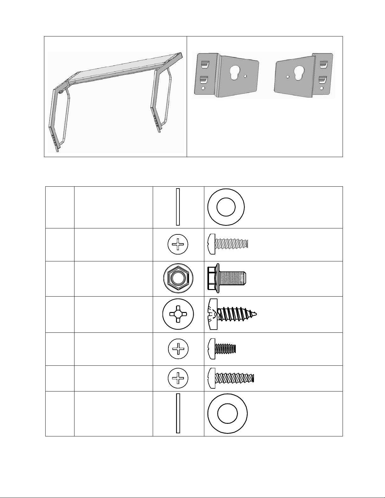
Overhead Lighting (optional)
Power Strip Brackets LH and RH (optional)
Hardware: Screws, Nuts, Washers, and Bolts
Washer, #10 Flat, Plain
Type A, Outside Dia. .5”
54225
(1.27 cm), Inside Dia.
.22” (.56 cm), .05” (.127
cm) Thick
54298
54348
59103
66714
80023
81710
Screw, #14B x 5/8”,
Phillips, Pan Head,
Thread Forming, Type B,
#3
Screw, 1/4 – 20 x 1/2”
Hex, Washer Head, SelfThreading
Screw, #10 - 3/4”,
Phillips, Pan Head,
Self-Tapping, Zinc
Screw, 10 -24 x 3/8”
Phillips, Pan Head,
Thread Forming, Black
Oxide
Screw, #10-24 x 3/4”
Phillips, Pan Head,
Thread-Forming
Washer, 5/16” SAE, Flat
Black, Plain Type A,
Outside Dia. ..69” (1.75
cm), Inside Dia. .34” (.86
cm), .06” (.15 cm) Thick
6
Installation Guide: TechBench™ / TechOrganizer - MN 212001EN r1.0
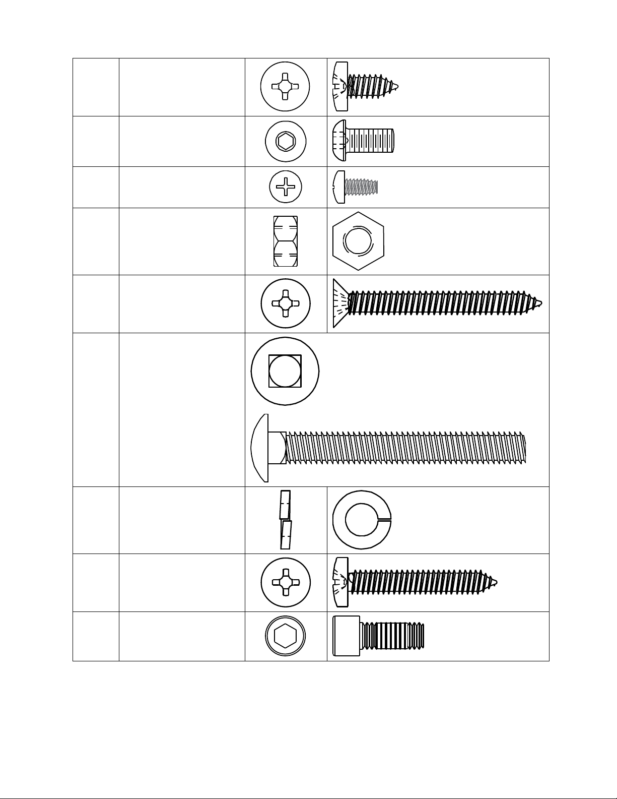
82287
Screw, #10-16 x 5/8”,
Phillips, Flat Head,
Self-Tapping, Zinc
82703
83645
84363
84742
85056
Screw, 1/4”-20 x 1/2”,
Button Head Cap, Black
Screw, 8-32 x 3/8”
Phillips, Pan Head,
Thread Forming
Nut, 3/8”-16
Screw, #10-16 x 2 1/4”,
Phillips, Flat Head,
Self-Tapping, Zinc
Carriage Bolt, 3/8”-16 x
3.00”
Washer, Split Lock, 3/8"
85057
Inside Dia., 11/16”
Outside Dia.
Screw, #10-16 x 1 3/4”,
85320
Phillips, Pan Head,
Self-Tapping, Zinc
91360
Screw, 5/16” x 3/4”,
Socket Head Cap
Installation Guide: TechBench™ / TechOrganizer - MN 212001EN r1.0
7

Linear TechBench™ Assembly
The following procedure applies to Linear Type A TechBench™ and T echOrganizer Systems
installed with the Laminate Worksurface in widths of 48 inches (121.9 cm), 60 inches (152.4
cm), and 72 inches (198.1.cm).
TechBench™ Adjustable Height
The base height of the TechBench™ Laminate Worksurface can be adjusted by removing the
eight Carriage Bolts along the Lower Side Frames and sliding the Upper Side Frames upward
(to raise) or downward (to lower) the height of the surface. The adjustable range for the
Lower and Upper Side Frame base structure is 30” (76.2 cm) to 35” (89.9 cm). To determine
the full height of the Worksurface, the Side Frame base measurement must be added to one
of the following; either the variable height set for the Leveling Glide Feet, which is between .5
(1.27 cm) to 2.5” (6.35 cm), or the fixed height of 5.625” (14.29 cm) if Casters are installed.
The Worksurface height level range varies slightly depending on whether the
TechBench™ is installed with Leveling Glides or Casters. Leveling Glides have
an adjustable range of .5” (1.27 cm) to 2.5” (6.35 cm). Casters are not
adjustable and have a fixed height of 5.625” (14.287 cm).
A minimum of three people are required to adjust the height of the worksurface
once the Linear TechBench™ and TechOrganizer System are assembled and in
the upright position. Attempting to adjust the height of an upright system without
the assistance of two additional installers may result in serious injury.
NOTE
WARNING
TechBench™ With Leveling Glides Installed
If Leveling Glides are attached to the bottom of the TechBench™, the height of the
Worksurface can be adjusted from a minimum of 30.5” (77.47 cm) to a maximum of 37.5”
(95.25 cm).
The minimum value above is calculated with the Leveling Glide feet fully
NOTE
retracted to a height of .5” (1.27 cm). The maximum value is calculated with the
Leveling Glide feet fully extended to a height of 2.5” (6.35 cm).
TechBench™ With Casters Installed
If Casters are attached to the bottom of the TechBench™, the height of the Worksurface can
be adjusted from a minimum of 35.625” (90.49 cm) to a maximum of 40.625” ( 103.19 cm).
The minimum and maximum values calculated for Caster-attached benches
includes 5.625” (14.29 cm), which is the a fixed height of each Caster.
NOTE
Before starting this procedure, identify/obtain the Worksurface height requirements
NOTE
for the TechBench™ to be assembled. It is much easier to adjust the height of the
Worksurface while the bench is face down on the floor, prior to turning the bench to
an upright position.
NOTE
8
Throughout the procedure, letter and number callouts within a figure only apply to
the figure in which they appear.
Installation Guide: TechBench™ / TechOrganizer - MN 212001EN r1.0

Step 1: Separate Upper Side Frame from Lower Side Frame
Locate the two Side Frames
within the installation kit.
Separate each Upper Side
Frame (5) from each Lower
Side Frame (4) by removing the
four Carriage Bolts (1),
Washers (2), and Nuts (3), on
both units. See Figure 1.
NOTE
Set the Lower Side Fram es and
hardware aside for r e-assembly
in a later step.
Carriage Bolt, 3/8-16 x
1
3.00” Long (85056)
Washer, Split Lock, 3/8"
2
Dia. (85057)
3
Nut, 3/8-16, (84363)
4
Lower Side Frame
Figure 1: Separate Upper and Lower Side Frames
5
Upper Side Frame
Installation Guide: TechBench™ / TechOrganizer - MN 212001EN r1.0
9

Step 2: Attach Stiffeners to Upper Side Frames
Locate the two Stiff eners (3) in
the installation kit. Attach the
Stiffeners to the Upper Side
Frames (2) as shown in Figure
2. See DETAIL A below.
Screw, 1/4”-20 x 1/2” Hex
1
Washer Head, SelfThreading [54348]
2
Upper Side Frames
3
Stiffeners
DETAIL A
A
Slot on Side Frame
B
Tongue Slides Into Slot
IMPORTANT! Flange Must Be
C
Positioned On Top as Shown
Figure 2: Attach Stiffeners to Upper Side Frames
DETAIL A
Screw, 1/4”-20 x 1/2” Hex Washer
1
Head, Self-Threading (54348)
2
Upper Side Frame
3
Stiffener End
4
Side Frame Post
At each corner, sl ide the tongue (B) at end
of Stiffener (3) into slot (A) on Side Frame
(2). Secure using six, Hex Washer Head,
Self-Threading screws (1).
Fully Assembled Corner
10
Installation Guide: TechBench™ / TechOrganizer - MN 212001EN r1.0

Step 3: Attach Upper Side Frame and Stiffener Assembly to Worksurface
Place Laminate Worksurface Face Down
Using two people, locate the Laminate
Worksurface in the installation kit. Carefully
unpack the W orksurface and place it finished
side down on the em pty carton or on a clea n
carpeted surface.
NOTE
The pre-drilled ho les locate d on the un dersid e
of the Laminate Worksurface should be facing
upward as shown in Figure 3.
Secure Side Frames and Stiffeners to Worksurface
Place the Upper Side Frame and
Stiffener assembly (B) on the
underside of the Worksurface (A),
as shown in Figure 4.
Secure Stiffeners to Worksurface
using ten, #10AB x 5/8” Ph i llips Pa n
Head screws (1).
Secure Upper Side Frames to
Worksurface using eight, #10 x 13/4” Phillips Pan Head screws (2),
with #10 Flat Washers (3).
Figure 4: Secure Side Frames and Stiffener to Worksurface
Figure 3: Laminate Worksurface Underside
A
Worksurface Underside
Upper Side Frame and
B
Stiffener Assy
Screw, #10AB x 5/8” Phillips
1
Pan Head, Black (82287)
Screw, #10 x 1-3/4”, Phillips
2
Pan Head (85320)
Washer, #10 flat
3
(54225)
Installation Guide: TechBench™ / TechOrganizer - MN 212001EN r1.0
11

Step 4: Attach Accessory Bracket and Two Drawer Pedestal (optional)
NOTE
If NOT attaching the optional Accessory
Bracket and Two Dra wer P edes ta l, the n GO
TO Step 5: Determine Worksurface Height
and Re-Attach Lower Side Frames, page
14.
With the Upper Side Frame and Stiffener
assembly firmly attached to the underside
of the Worksurface, secure the Accessory
Bracket (1) to the front and back Stiffeners
using four, #14B x 5/8”, Phillips, Pan Head
screws (2), as shown in Figure 5.
NOTE
The illustration shows the Accessory
Bracket centered along the front Stiffener.
Depending on user preference, the
Accessory Bracket and Two Drawer
Pedestal may also be attached to loc ations
left or right of center.
Point flange on front edge of
A
Accessory Bracket towards Laminate
Worksurface underside.
Figure 5: Attach Accessory Bracket to Stiffeners
Abut inside edge of flange to outside
B
edge of front Stiffener.
C
FRONT edge of Worksurface.
1
Accessory Bracket
Screw, #14B x 5/8”, Phillips, Pan
2
Head (54298)
Secure Hanger Screws to Accessory Bracket
After the Accessor y Bracket is fastened to
the front and back Stiffeners, secure the
four Pedestal Hanger screws (1) to the
bottom of the Accessory Bracket (2), as
shown in Figure 6.
CAUTION
Do NOT over-tighten Hanger screws.
Pedestal Hanger screws; Qty. 4
1
Shipped with Two Drawer Pedestal
Figure 6: Secure Hanger Screws to Accessory
Bracket
2
Accessory Bracket (bottom)
12
Installation Guide: TechBench™ / TechOrganizer - MN 212001EN r1.0

Attach Two Drawer Pedestal to Accessory Bracket
WARNING
To avoid injury, it is recommended that
two installers work together to lift the
Pedestal (1) onto the Accessory
Bracket (2).
As shown in Figure 7, to attach the
Two Drawer Pedestal (1), turn the
Pedestal upside down and place the
four key-slots in the top surface of the
Pedestal over the four Hanger screws
(A) on the Accessory Bracket (2). To
lock the Pedestal in place, push/slide
the Pedestal towards t he rear (B) until
the spring clips inside the Pedestal
holes lock into place.
A
Hanger Screws (4)
Sliding Pedestal Towards Rear
B
Locks Spring Clips in Place
C
FRONT of TechBench™
D
REAR of TechBench™
1
Two Drawer Pedestal
Figure 7: Attach Pedestal to Accessory Bracket
2
Accessory Bracket (bottom)
Installation Guide: TechBench™ / TechOrganizer - MN 212001EN r1.0
13

Step 5: Determine Worksurface Height and Re-Attach Lower Side Frames
Determine Worksurface Height
Figure 8 shows a view of the TechBench ™, up-side down, with the W orksurface flat on the flo or and
the Lower Side Fram es (2) separated from the Upp er Side Frames (1). As sho wn, when assembled,
the Upper Side Frames (1) slide inside the Lower Side Frames (2) and eight, Carriage Bolts (3),
Washers (4), and Nuts (5) are used to fasten the components together at a specific height.
Figure 8: Determine Worksurface Height
When adjusting the TechBench™ to set the Worksurface height, two factors (measurements ) must be
taken into consideratio n. T he firs t measur em ent (setti ng) is the height of the T echBenc h™ bas e, whic h
includes the Upper and Lower Side Frames along with the thick ness of the Lam inate W orksurface. As
shown in Figure 8, this ranges from 30” (76.2 cm) to 35” (89.9 c m). The second factor (m easurement)
is the height of the adjustable Leveling G lide Feet (range .5 (1.27 cm ) to 2.5” (6.35 cm), or the fixed
height of the Caster Wheels, 5.625” (14.29 cm), depending upon which are installed. To
obtain/achieve the full he ight of the Worksurface, the base measurement must be added to the
height of the Leveling Glides or Casters, depending upon which ones are to be attached.
To secure the base he ight, line up the holes and C arriage Bolts (A) located on the Lower Side Rails
with the d esired holes (items 30-35) on the Upper Side Rails. Once all bo lts are ins erted, sec ure using
the Washers (4) and Nuts (5) provided.
To determine the full height of the Worksurface, the Side Frame measurement,
30” (76.2 cm) to 35” (89.9 cm), must be added to the height set for the Leveling
Glides, .5 (1.27 cm) to 2.5” (6.35 cm), or Coasters, 5.625” (14.29 cm) fixed,
NOTE
depending upon which ones will be installed on the TechBench™.
14
Installation Guide: TechBench™ / TechOrganizer - MN 212001EN r1.0

Re-Attach Lower Side Frames
NOTE
When setting the height, remember to
add the height of the Leveling Glide
Feet, .5” (1.27 cm) to 2.5” (6.35 cm ), or
Coasters, 5.625” (14.29 cm) fixed, to
the base measurement, depending
upon which ones will be installed. For
details, see Determine Worksurface
Height, on page 14.
NOTE
Leveling Glide Feet will be adjusted in
the next step. If Leve ling Glide Fee t are
to remain on the TechBench™ (not
removed), select a measurement for
the Leveling Glide Feet (to be used in
the next step), and add that valu e to the
base measurement when determining
the full height of the Worksurface for
this step.
For Casters, add the fixed value of
5.625” ( cm).
As shown in Figure 9, re-attach the
Lower Side Frames (1) to the Upper
Side Frames (2) using the eight
Carriage Bolts (3), Washers (4), and
Nuts (5) removed in Step 1.
Figure 9: Re-Attach Lower Side Frames
1
Lower Side Frame
2
Upper Side Frame
Carriage Bolt, 3/8-16 x 3.00”
3
Long (85056)
Washer, Split Lock 3/8" Dia.
4
(85057)
5
Nut, 3/8-16 (84363)
Installation Guide: TechBench™ / TechOrganizer - MN 212001EN r1.0
15

Step 6: Adjust Height of Leveling Glides
e bottom of the
NOTE
If Casters and the Foot Rest are to be
attached to th
TechBench™, skip this step and GO TO
Step 7: Attach Casters and Foot Rest to
Bottom of TechBench™ (optional), on
page 16.
To adjust Leveling Glides, use a 1/2” open
end wrench at Notch position (3). Turn
Counter Clockwise (CCW) to increase
distance (A) and Clockwise (CW) to
decrease. Use a 1” open end wrench to
loosen/tighten Check Nut (2). Tighten
Check Nut once Levelin g Glid e Foot is set.
See Figure 10.
Leveling Glide range is 0.5” (12.7 mm)
A
minimum, to 2.5” (63.5 mm) maximum.
1
Leveling Glide Foot
2
Check Nut (1”)
3
Notch (1/2”)
Once Leveling Glide height adjustments
are complete, GO TO Step 8: Attach Back
Panel, on page 18.
Figure 10: Adjust Leveling Glide Height
NOTE
Set all four Leveling Glides to the same measurem ent
(A). Leveling Glide ra nge is .5” (12.7 m m ) to 2.5” (63.5
mm).
16
Installation Guide: TechBench™ / TechOrganizer - MN 212001EN r1.0

Step 7: Attach Casters and Foot Rest to Bottom of TechBench™ (optional)
NOTE
If Casters and Foot Rest are NOT to be installe d,
then skip this step an d GO TO Step 8: Attac h Bac k
Panel, on page 18.
Remove Leveling Glide Feet
Before Casters can b e attached, the four Leveling
Glide Feet (1) must be removed.
To remove the Leveling Glide Feet (Figure 11), use
a 1/2” open end wrench on the Notch point (see
Figure 10, on page 16 to view Notch location).
Turn Leveling Glide CCW to remove.
1
Four Leveling Glide Feet
Attach Casters to TechBench™
Figure 11: Remove Leveling Glide Feet
As shown in Figure 12, attach Locking
Casters (1) to the front (A) of the
Figure 12: Attach Casters to TechBench™
TechBench™, and Non-Lo cking Casters
(2) to the rear of the TechBench (B).
NOTE
When attaching Locking Casters (1),
make sure the Lock ing Me c hanism (C) is
pointing forwards, to wards the front, as
shown.
Secure each Caster to th e TechBench™
using four, 5/16” x 3/4” Long, Socket
Head Cap screws, and 5/16” Washers.
Tighten screws using 1/4” Allen wrench.
A
FRONT of TechBench™
B
REAR of TechBench™
C
Locking Mechanism
1
Locking Caster
2
Non-Locking Caster
Screw, 5/16” x 3/4” Long,
3
Socket Head Cap (91360)
Washer, 5/16” SAE, Flat Black
4
(81710)
NOTE
Casters add 5.65” (142.24 mm) to height of Worksurface.
Installation Guide: TechBench™ / TechOrganizer - MN 212001EN r1.0
17

Attach Foot Rest to TechBench™
As shown in Figure 13, attach the Foot Rest
(1) to the inside edges of both lower Side
Frames using four, 1/4”-20 x 1/2” Hex
Washer Head, Self-Threading screws (2).
NOTE
The Foot Rest (1) is typical ly attached to the
most forward location along the inside of the
lower Side Fram es (A), as shown. Additio nal
holes are available on both sides to
position/re-locate the Fo ot Rest further back
if necessary.
A
Front of TechBench™
1
Foot Rest
Screw, 1/4”-20 x 1/2” Hex Washer
2
Head, Self-Threading (54348)
Step 8: Attach Back Panel
Using six, 1/4”-20 x 1/2” Hex
Washer Head, Self-Threading
screws (3), attach the Back
Panel (1), to the rear of both
Side Frames (2), as shown in
Figure 14.
Figure 13: Attach Foot Rest to TechBe n ch
Figure 14: Attach Back Panel
1
Back Panel
2
Side Frames (rear)
Screw, 1/4”-20 x 1/2”
3
Hex Washer Head, SelfThreading (54348)
18
Installation Guide: TechBench™ / TechOrganizer - MN 212001EN r1.0

Step 9: Turn the TechBench™ Upright
WARNING
To avoid injury, it is recommended that
two or more installers work together to
turn the TechBench™ upright.
As shown in Figure 15, turn the
TechBench™ upright so it is resting on
either the Casters or Leveling Glides.
NOTE
If Casters were installed on the
TechBench™, there is no need for
leveling. GO TO Step 10: Attach
TechOrganizer to Worksurface, on page
20.
Level TechBench™ Worksurface
If Casters were NOT installed on the
TechBench™, then place a Leveling
device on the Worksurface (A) and level
the Worksurface by adjusting the height
of the four Leveling Glides (1).
To adjust the Le vel ers , us e a 1” o pe n end
wrench to loosen the Check Nut. Use a
1/2” open end wrench on the Leveler
Notch to adjust th e Leveler height (CCW
to raise a corner and CW to lower).
Tighten all four Check Nuts once final
adjustments are made. For a detailed
view of the Leveling Glide, see Figure 10,
on page 16.
Figure 15: Turn TechBench™ Upright
Installation Guide: TechBench™ / TechOrganizer - MN 212001EN r1.0
19

Step 10: Attach TechOrganizer to Worksurface (optional)
As shown in Figure 16, position the
TechOrganizer (1) along the rear of the
Worksurface (2).
Adjust the rear edge of the TechOrganizer
(1) so that it is .2” (5.08 mm) from the rear
edge of the Worksurface (A).
Using a plastic mallet, tap the en ds of the
TechOrganizer frame to ensure both feet
and frame are at a 90° a ngle in reference
to the corner of the Worksurface.
Using the holes along the frame bottom
crossbar (B) and both feet (C) as a
template, drill holes .113” (2.97 mm) in
diameter and .5” (12.7 mm) deep.
NOTE
Use a 7/64 drill bit to drill holes.
NOTE
It may be easier to m ark all drill loc ations
first, using the TechOrganizer as the
template, then rem ove the TechOrganizer,
drill the holes, and reposition the
TechOrganizer back along the
Worksurface edge.
Once all holes are drilled and the
TechOrganizer is repositioned, attach the
TechOrganizer bottom frame to the
Worksurface using four , #10 – 2 1/4” Long,
Phillips Flat Head, Self-Tapping screws
(4). Attach both feet to the Worksurface
using four (two per side), #10 - 3/4” Long,
Phillips Pan Head, Self-Tapping screws
(3).
Figure 16: Attach TechOrganizer to Worksurface
Position rear edge of TechOrganizer
A
.2” (5.08 mm) from rear edge of
Worksurface.
B
TechOrganizer Frame
C
TechOrganizer Feet
1
TechOrganizer
2
Worksurface
Screw, #10 - 3/4” Long, Phillip s Pa n
3
Head, Self-Tapping, Zinc (59103)
Screw, #10 – 2 1/4” Long, Phillips
4
Flat Head, Self-Tapping, Zinc
(84742)
20
Installation Guide: TechBench™ / TechOrganizer - MN 212001EN r1.0

Step11: Attach Mounting Channels and Bin Board to TechOrganize r (optional)
12: Attach Overhead Lighting to
NOTE
If Bin Board an d Mounting Channels are
NOT to be installed, then GO TO
TechOrganizer (optional), on page 23.
NOTE
Bin Board and Mounting Channels
MUST be installed BEFORE
components that might extend across
the face of the bo ard, such as a ho ok on
shelf.
NOTE
Figure 17 shows the Bin Board and
supporting Mounting Channels attached
to the lower right section of the
TechOrganizer. The Bin Board can be
installed at other locations along either
side of the TechOrganizer by relocating
the Mounting Channels accordingly.
Step
Figure 17: Mounting Channels and Bin Board
Assembly
1
Bin Board
2
Mounting Channels
Screw, #10-24 x 3/4” Phillips, Pan
3
Head, Thread-Forming (80023)
Screw, #8 -32 x 3/8” Phillips, Pan
4
Head, Thread-Forming, (83645)
A
TechBench™ Worksurface
TechOrganizer Frame with Slotted
B
Standards
Embossed Triangle on Mounting
C
Channels – MUST BE AT TOP,
when Installed.
As shown in Figure 17
, attach each
Mounting Channel (2) al ong the inside of
the Slotted Standards (B) using eight,
#8-32 x 3/8” Phillips, Pan Head, ThreadForming screws (4). Make sure to
position the Embossed Triangle at the
TOP (C) during installation.
Installation Guide: TechBench™ / TechOrganizer - MN 212001EN r1.0
21

Attach Bin Board to Mounting Channels
1
Bin Board
2
Mounting Channels
Screw, #10-24 x 3/4” Phillips, Pan
3
Head, Thread-Forming (80023)
Bin Board Panel Hooks (three on
A
each side)
To attach the Bin Board (1) to the Mounting
Channels (2), align the Panel Hook s (A) on the
back of the Bin board with the rectangular slots
on each Mounting Channel. See Figure 18.
Figure 18: Line Up Panel Hooks
Figure 19: Insert Panel Hooks Into Channel Slots
As shown in Figure 19, ins ert and firmly seat
the three Panel Hooks (A) along each side
into the slots on the Mounting Channels (2).
NOTE
Use a flat blade screwdriver as a lever or
plastic mallet as required.
Secure the Bin Panel to the Mounting
Channels using two, #10-24 x 3/4” Phillips,
Pan Head, Thread-Forming screws, as shown
in Figure 20.
Figure 20: Secure to Mounting Channe ls
22
Installation Guide: TechBench™ / TechOrganizer - MN 212001EN r1.0

Step 12: Attach Overhead Lighting to TechOrganizer (optional)
5
6
NOTE
If the Overhead Light is NOT t o be installed, then GO TO Step 13: Attach Lam inate Hook-On Shelf
(optional), on page 26.
Overhead Lighting Components
Figure 21: Overhead Lighting Components
Figure 21 shows the components com prising the
Overhead Lighting assembly. As illustrated, the
assembly consists of the Overhead Light (1), two
Support Brackets (2), two Mountin g Spacers (3),
and the hardware Screws (4, 5 and 6) , used for
interconnecting t he com ponents toge ther an d for
fastening the unit to the TechOrganizer.
NOTE
The Overhead Light (High Profile Model) hooks
onto the slotted standard (trapezoid shaped
holes) at the top of the TechOrganizer. If
attached to the very top, the light will sit 12”
above the top of the frame.
Installation Guide: TechBench™ / TechOrganizer - MN 212001EN r1.0
1
Overhead Light (High Profile Model)
2
Support Bracket
3
Mounting Spacers
4
Screw, 1/4”-20 x 1/2”, Button Head (82703)
Screw, 10 -24 x 3/8” Phillips, Pan Head,
+
Thread Forming, Black Oxide, (66714)
23

Attach Support Brackets to TechOrganizer
Brackets (1) will be attached to the
Figure 22: Hook Support Brackets onto TechOrganizer
Select the position (height) where the Support
TechOrganizer (3). Insert the Hooks (A) into the
Slotted Standard (B). Tap the brackets down
making sure the hook s are seated firml y into the
frame. As shown in
Figure 22, secure the
brackets to the standards using two, 10-24 x 3/8”
Phillips, Pan Head, T hr ead F orm ing, B lack Oxide,
screws (2).
24
1
Support Brackets
Screw, 10 -24 x 3/8” Phillips, Pan Head,
2
Thread Forming, Black Oxide, (66714)
3
TechOrganizer Frame
A
Hooks
B
Slotted Standard (trapezoid shaped holes)
Installation Guide: TechBench™ / TechOrganizer - MN 212001EN r1.0

Attach Mounting Spacers to Overhead Light
Figure 23: Attach Mounting Spacers to Overhead Light
The Mounting Spacers (2) must be attach ed to the ends of
the Overhead Light (1) b efore the light can be secured to
the Support Brackets.
As shown in Figure 23, secure the Mount ing Spacer s (2) t o
the Overhead Light (1) us ing six, 10-2 4 x 3/8” Phillips , Pan
Head, Thread Forming, Black Oxide, screws.
Attach Overhead Light to Support Brackets
Figure 24: Attach Overhead Light to Support Brackets
1
Overhead Light
2
Mounting Spacers
Screw, 10 -24 x 3/8” Phillips,
3
Pan Head, Thread Forming,
Black Oxide, (66714)
Once Mounting Spacers are attached to both ends of the
Overhead Light (1), it can be attached to the top of the
Support Brackets (2), using four, 1/4”-20 x 1/2”, Button
Head, screws, as shown in Figure 24.
NOTE
1
Overhead Light
2
Support Brackets
Screw, 1/4”-20 x 1/2”,
3
Button Head, (82703)
The Overhead Light can be mounted in three different
locations (front to back) along the top of the Support
Brackets.
Installation Guide: TechBench™ / TechOrganizer - MN 212001EN r1.0
25

Step 13: Attach Laminate Hook-On Shelf (optional)
are pointing inward towards one another.
NOTE
If Laminate Hook-O n Shelf is NOT to be installe d, then G o So Step 14: Attach LH and RH Power Str ip
Brackets (optional), on page 28.
Attach Shelf Supports to Laminate Shelf
Figure 25: Attach Shelf Supports to Laminate Shelf
Before the Laminate Hook-On Shelf can be
installed, the Shelf Support s (2 and 3) must first
be attached to the Laminate Shelf Underside (1).
As shown in Figure 25, lay the Laminate Shelf
(1) with the finished side down on an empty
carton or on a clean carpeted surface. Then
position the Left H and ( LH) and Right Hand ( RH)
Shelf Supports (2 and 3) on the underside as
shown and secure both Supports to the
Laminate Shelf using four, #10AB x 5/8” Phillips,
Pan Head, Black, screws.
A
Square Holes at Rear of Shelf
B
Hooks on Shelf Supports
1
Laminate Shelf Underside
2
LH Shelf Support
3
RH Shelf Support
Screw, #10AB x 5/8” Phillips, Pan Head,
4
Black, (82287)
NOTE
For proper positioning, make sure the hooks (B)
on both supports are pointing towards the s quare
holes at the rear of the s helf (A) and the flanges
26
Installation Guide: TechBench™ / TechOrganizer - MN 212001EN r1.0

Attach Laminate Shelf to the TechOrganizer
Figure 26: Attach Laminate Shelf to TechOrganizer
Identify the height a t which the Laminate HookOn Shelf will be ins talled. I nsert the ho oks at the
front of the LH and RH Shelf Supports (2 and 3)
into the corresponding holes along both
Standards (A).
As shown in Figure 26, secure the shelf to the
TechOrganizer using two, 10-24 x 3/8” Phillips,
Pan Head, Thread Forming, Black Oxide,
screws.
Installation Guide: TechBench™ / TechOrganizer - MN 212001EN r1.0
A
Standards with Trapezoid Shaped H o les
1
LH Shelf Support
2
RH Shelf Support
Screw, 10 -24 x 3/8” Phillips, Pan Head,
3
Thread Forming, Black Oxide, (66714)
NOTE
Use a flat blade screwdriver as a lever or a
plastic m allet to tap the brackets down m aking
sure the hooks are seated firmly into the frame.
27

Step 14: Attach LH and RH Power Strip Brackets (optional)
NOTE
If LH and RH Power Strip Brackets are NOT to be installed, then this procedure is complete.
Figure 27: Attach Power Strip Brackets to TechOrganizer
As shown in Figure 27, attach the LH and RH
Power Strip Brackets (1 and 2) to the Standards
(A) by inserting the hooks at the back of each
bracket into the Standard holes and securing
each bracket using one, 1/4”-20 x 1/2” Hex
Washer Head, Self-Threading, screw (3).
PROCEDURE COMPLETE.
A
Standards with Trapezoid Shaped H o les
1
LH Power Strip Bracket
2
RH Power Strip Bracket
Screw, 1/4”-20 x 1/2” Hex Washer Head,
3
Self-Threading (54348)
28
Installation Guide: TechBench™ / TechOrganizer - MN 212001EN r1.0

© Copyright 2013 Eaton Corporation, Worcester, MA, USA.
Eaton Corporation
To contact an Eaton salesperson
All rights reserved.
Information in this document is subject to change without notice. No part of this document may
be reproduced or transmitted in any form or by any means, electronic or mechanical, for any
purpose, without the express written consent of Eaton Corporation.
Eaton is a registered trademark of Eaton Corporation or its subsidiaries and affiliates. Phillips is
a registered trademark of Phillips Screw Company. All other trademarks are the property of
their respective owners.
Electrical Sector
1111 Superior Ave.
Cleveland, OH 44114
United States 877-ETN-CARE (877-386-2273)
Eaton.com © 2013
Eaton Corporation
All Rights Reserved
Publication No
MN 212001EN r1.0
or local distributor, please visit
www.eaton.com/wrightline or
call 800-225-7348.
Installation Guide: TechBench™ / TechOrganizer - MN 212001EN r1.0
29
 Loading...