

Eaton UltraShift PLUS EO-11E406B-PV, UltraShift PLUS EO-11E406B-PVER Installation Manual

Installation Guide
Eaton Medium-Duty
UltraShift® PLUS Transmissions
TRIG0996 EN-US
September 2014
Eaton UltraShift® PLUS PV Performance Transmissions
EO-11E406B-PV
EO-11E406B-PVER


General Information
Introduction and General Information ......................... 1
Warnings and Cautions ............................................... 1
Important Notice ........................................................ 1
About this Manual ...................................................... 2
OEM Design Responsibility ........................................ 2
Application Approval .................................................. 2
Transmission Identification Tag ................................. 3
Product Identification
Nomenclature ...................................................... 3
Product Familiarization ................................................ 4
Similarities and Differences Compared to
Current Automated Products ...................................... 4
Similarities with Eaton UltraShift® PLUS PV
Products compared to UltraShift® HV Products ........ 4
Differences and Features with
Eaton UltraShift PLUS PV Products ........................... 4
Suggested Tools/Publications ..................................... 5
Vendor List .................................................................. 6
Vehicle Space Claim
Cab Floor Access Plate Requirements ........................ 8
Shift Label Requirements ........................................... 9
Eaton Shift Console Space Requirements ................ 10
Eaton Shift Lever and Tower Space Requirements ... 11
Clutch Interface
Pilot Bearing Specifications ...................................... 12
Clutch Installation
395 Clutch Installation Requirements ................ 13
395mm Mounting Bolts and Shipping Bolts ...... 14
ECA Assembly Instructions ................................15
ECA Removal Instructions .................................. 16
Transmission Interface
Handling ................................................................... 17
Transmission Preparations ...................................... 17
Reverse Switch
Reverse Switch Option ....................................... 17
Reverse Switch .................................................. 17
Mounting Transmission to Engine
Using Rear Supports ..........................................18
Table of Contents
ECA Engine Speed Sensor Requirements ................. 19
Threaded Engine Speed Sensor
Installation Requirements ...................................19
Lubrication Requirements and Specifications
Eaton UltraShift PLUS PV Transmission
Gear Box Lubrication Requirements ...................20
Warnings and Cautions ......................................20
Operating Temperatures .....................................20
Transmission Oil Level .......................................21
Transmission Component
Temperature Requirements .......................................22
Right Side View ........................................................ 22
Top View ................................................................... 23
Left Side View ........................................................... 24
Electrical System Interface
Definitions ................................................................ 25
Power Requirements and Recommendations
Battery Power Requirements
and Recommendations .......................................26
Medium Duty Power Architecture Option ...........27
Medium Duty Power Architecture Option ...........28
Electrical Harnessing Integration Examples ........29
ECA Power Harness ............................................30
Typical ECA Circuit .............................................31
Typical TCM Circuit ............................................32
Electrical Current Requirements
and Recommendations.............................................. 33
Operating Conditions over Temperature
for 24-Volt Systems .................................................. 33
OEM on Transmission Routed Components
Routable Component Requirements ...................34
Mating Connector and Terminal Requirements
TCM ....................................................................34
ECA .....................................................................35
Engine Speed Sensor Interface ...........................35
PBSC ..................................................................36
Eaton Shift Lever ................................................37
General Requirements .............................................. 37
Network Communications Requirements ................. 38
Typical System Wiring for SAE J1939/13
Diagnostic Connector ................................................39

Table of Contents
Electrical System Interface (continued)
Typical System Wiring for SAE J1939/11
and SAE J1939/15 .................................................... 40
Vehicle Service Requirements for Electronics .......... 41
Electrical/Electronic Vehicle System
Hardware Requirements
Start Enable Relay Requirements
and Recommendations ...................................... 41
J1939 Start Enable Requirements...................... 41
Typical Start Enable Circuit ................................ 42
Typical Relay Isolated PTO Input ....................... 43
PTO Switch Input Requirements
Typical Switched PTO Input............................... 44
Auto Neutral Switch Requirements
Typical Auto Neutral Switch Input...................... 45
Eaton PBSC Installation Requirements
Typical System with Eaton PBSC ....................... 46
Eaton Shift Lever and Resistive Ladder Shift
Device Requirements
Typical System Wiring with OEM Resistive Ladder
Shift Device ........................................................47
Typical System Wiring with Eaton Shift Lever .... 48
OEM J1939 Based Shift Devices
Typical System Wiring with OEM SAE J1939
Shift Input Device .............................................. 49
Dimmer Control Input Requirements for PBSC
and Eaton Shift Lever
Typical Eaton Shift Device System Wiring
for Dimmer Control Input Control ...................... 50
Service Lamp Requirements
Service Lamp TCM Connection Requirements... 50
Service Lamp SAE J1939................................... 50
Eaton Installed Reverse Switch Electrical
Requirements and Recommendations ..................... 51
Vehicle Electrical/Electronic System Component
Recommendations
Relay Recommendations ................................... 51
Harness Design, Routing, and Attachment
Recommendations
Mating Connector and Terminal
Recommendations............................................. 52
Electrical Sealing Recommendations ................. 52
Harness Design Recommendations ................... 52
Harness Routing Recommendations.................. 52
Harness Attachment Recommendations ............ 53
Table of Contents
Contact Lubrication Recommendation ...................... 53
Additional Harness Design Recommendations ......... 53
Electrical Juncture Recommendations ...................... 55
Troubleshooting Recommendations
Harness Troubleshooting and Test Equipment Design
Recommendations .............................................55
Vehicle Service Recommendations for Electronics ... 55
Electrical Reference Diagrams
Routing Attachment Points................................. 56
SAE Cable Insulation Outside
Diameter Reference ............................................ 57
Wiring Diagram - OEM Responsibility
UltraShift PLUS PV with Eaton Shift Lever ......... 58
UltraShift PLUS PV with Eaton PBSC ................. 59
UltraShift PLUS PV Wiring Diagram with Analog
Shifter................................................................. 60
UltraShift PLUS PV Wiring Diagram
with PBSC Shifter ............................................... 61
Connector Pin Descriptions
Transmission Controller 38-Way (Vehicle
Interface Connector)........................................... 63
Cobra Lever 8-way Connector ............................ 64
Electric Clutch Actuator (ECA) 3-way Connector 64
PBSC 30-Way Connector.................................... 64
System Integration Specifications
SAE J1939 Data Link Broadcast Messages................ 65
Broadcast On Request To Transmission ................... 68
SAE J1939 Data Link Received Messages ................. 70
Received On Request From Transmission ................ 74
SAE J1587 Data Link Broadcast Messages................ 75
Gear Display .............................................................. 76
Defined Control Characters ....................................... 76
Minimum Gear Display Alphanumeric
Combinations ........................................................... 77
Auto Neutral .............................................................. 78
Shift Input Device ..................................................... 78
Engine ....................................................................... 78
J1939 Start Enable Functionality .............................. 78
Alert Tone ................................................................. 79
Service Lamp ............................................................ 79
OEM Vehicle Equipment Programming
Station (VEPS) .......................................................... 79

Auxiliary Equipment Interface
PTO Inputs and Configurations
PTO Inputs ........................................................ 80
PTO Configurations ........................................... 80
Line Inspection and End of Line
Line Inspection and Road Test Instructions ............. 81
Line Inspection ......................................................... 82
Pre-Start Inspection and Initial
Starting Requirements
Pre-Start Inspection ........................................... 82
Before Cranking Engine ...................................... 83
Grade Sensor Calibration
Process Requirements....................................... 84
Grade Sensor Calibration Tool ........................... 84
Shift Input Device Combination ......................... 85
ServiceRanger (PC-based Diagnostic Tool) ....... 85
Line Inspection Forms
Eaton UltraShift PLUS PV Models ..................... 86
OEM Wiring Connector/Harness ....................... 87
Diagnostic Procedure ............................................... 88
Table of Contents
Appendix
Torque Specifications................................................ 91
Change Control Log ................................................... 92
Warnings and Cautions
Warnings and Cautions
Introduction and General Information
Warnings and Cautions
This symbol is used throughout this
manual to call attention to procedures
whe re carelessness or fa ilur e to follow
specific instructions may result in
personal injury and/or component
damage.
Departure from the instructions, choice
of tools, materials and recommended
parts me ntioned in this public ation
may jeopardize the personal safety
of the service technician or vehicle
operator.
!
Warning: Failure to follow indicated
procedures crea te s a high risk of pers onal
injury to the servicing technician.
Caution: Fai lure to follow indicated
procedure
damage or malfunction.
Important: Highly recommended
procedures for proper service of this unit.
Note: Additional servic e information not
covered in the service procedures .
Tip: Helpful removal and installation
procedures to aid in the ser
s may cause component
vice of this unit.
Important Notice
Any reference to brand name in this publication is made as an example of the types of tools and materials recommended for
use and should not be considered an endorsement. Equivalents may be used, unless otherwise stated.
The description and specifications contained in this service publication are current at the time of printing.
Eaton reserves the right to discontinue or modify its models and/or procedures and to change specifications at any time
without notice.
1

General Information
About this Manual
This Eaton® publication is intended to be a reference guide for the installation of the Eaton UltraShift® PLUS PV transmission.
General vehicle and transmission information is provided to cover the wide range of applications. This information benefits the
OEM installer by providing the correct installation procedures to ensure the utmost in satisfactory operation and long service life.
For additional transmission information, see the Suggested Tools section in this manual. For specific engine information contact
the engine OEM.
Failure to adhere to Eaton Installation Requirements may affect transmission performance and/or warranty coverage.
Eaton UltraShift® PLUS PV is compatible with electronically governed engines equipped with a J-1939 data link and certified by
Eaton. Transmissions installed at OEM facilities shall meet and be approved by Eaton Application Engineering. Contact Eaton
Application Engineering or your OEM Application Engineering department for the proper Application form. All applications shall
be submitted for approval.
OEM Design Responsibility
OEM facilities shall submit a design package to Eaton OEM Engineering Support Group for approval prior to any OEM build.
A design package consists of the following information:
• Battery power and ground - Detailed drawing of battery power and ground scheme.
• Individual harness drawings - Construction detail of individual wiring harnesses including harness routing location
and clipping points.
• Wiring schematic - High-level schematic of how this transmission interfaces with the vehicle.
Application Approval
Eaton UltraShift PLUS PV model transmission systems installed at OEM facilities must meet the requirements and be
approved using the Eaton Transmission Application Approval Form. Please contact Eaton Application Engineering or your
OEM's Application department for the latest Application form.
• Driveline Torque Requirements - Driveline angular acceleration and driveline torque shall not exceed requirements
stated in Eaton Application Guideline specification TRAG2600.
• Applications and PTO Applications- refer to Application Guidelines Manual TRAG2600 and PTO Torque Limits
TMIB0127 for PTO application guidelines.
Every effort has been made to ensure the accuracy of the information contained in this manual. However, Eaton makes no warranty, either expressed or implied, based on the information provided. With each new application, engine manufactures should be
contacted to make sure desired engines are compatible with these systems.
2

General Information
E
Newton meters
Overdrive
O
-
X 100 Newton meters
ECA clutch control
(same as HD)
Gear Ratio Set
Number of Speeds
11E406B-
PVER
Passenger Vehicle
Electromagnetic Retarder
Same Gear Design Level as all MD automated
current products (Park HV uses 5 because
they actually use a different mainshaft)
Mechicanical & Electronic
Transmission Identification Tag
All UltraShift transmissions are supplied with component identification tags. All tags are located on the bottom, right rear corner
of the transmission.
Care should be taken not to damage the identification tag during the installation process.
Do not remove the identification tag.
Model
Information
General
Serial
R
Eaton
Fuller
Transmissions
Product Identification
Nomenclature
Eaton UltraShift® PLUS PV Performance Transmissions
E
O
11E406B-
-
Newton meters
Overdrive
X 100 Newton meters
ECA clutch control
(same as HD)
Same Gear Design Level as all MD automated
current products (Park HV uses 5 because
they actually use a different mainshaft)
Mechicanical & Electronic
Made In
R
Eaton Corporation
Transmission Div.
Kalamazoo, MI. 49003
PV
Passenger Vehicle
No Retarder
Gear Ratio Set
Number of Speeds
3

General Information
Product Familiarization
Similarities and Differences Compared to Current Automated Products
Note: In all cases where differences have been identified, see the respective installation requirements for details.
Similarities with Eaton UltraShift® PLUS PV Products compared to
®
UltraShift
• Identical PTO locations and PTO fit up requirements.
• Identical shift device options.
• Utilizes Gen 3 ECU and electrical connections
• Includes advanced Gen 3 diagnostic capabilities.
• Identical reverse switch option and locations.
Differences and Features with Eaton UltraShift PLUS PV Products
HV Products
• A MEIIR circuit is not required for the Eaton UltraShift PLUS PV Transmissions.
• New 12/24 Volt capable Electric Clutch Actuator (ECA) to manage clutch engagement for improved transmission
shifting. This requires the OEM to connect a power harness and ground.
• New ECA Clutch which is automatically adjusted at the OEM prior to vehicle being driven.
• A zerk fitting for the ECA cross shaft is easily accessible on the outside of the clutch housing for servicing. The cross
shaft is pre-lubed by Eaton.
• Transmission rear supports are required with transmission mounted retarder.
• An intelligent start gear selection system automatically selects appropriate gear based on percent grade, vehicle weight
and engine torque. The OEM is required to perform a grade sensor calibration procedure upon initial vehicle start up to
support this system.
• A PTO input is available on this transmission. The OEM is recommended to provide a connector and wiring from the
transmission ECU 38-way with the PTO wires installed.
• A High Capacity Inertia Brake (HCIB) is located on the transmissions PTO opening. This device is installed by Eaton.
Therefore, a clutch brake is not required to be installed by the OEM.
• This system requires passive sealing on the clutch housing to ensure no foreign debris enters the clutch area. This
requires the OEM ensure that all openings in the flywheel housing are plugged.
• A 10 tooth 1 3/4 inch spline on the input shaft is standard for the PV transmission.
• An auto neutral feature is required with this transmission which forces neutral in all instances when the parking
brake is applied. This requires the OEM to install and connect a pressure switch in the parking brake valve circuit.
Starting with the release of software #5569892, a data link signal will be an acceptable substitute for the pressure
switch requirement.
• A direction sensor is a new device for this transmission which integrates the speed and directional signal into one
sensor, thereby requiring only one opening (12 o’clock position) on the rear bearing cover.
• A 12 or 24 volt electrical system with a minimum of 1800 CCA is required.
• Product-specific J1939 messaging.
• The OEM is required to install a flywheel speed sensor.
4

General Information
Suggested Tools/Publications
O.E. Tool & Equipment Group/Kent-Moore SPX Corporation 1(800) 520-2584
Kent-Moore Part no. Description
5505027 Volt/Ohm Meter (Standard commercially available VOM)
O.E. Tool & Equipment Group/Kent-Moore SPX Corporation 1(800) 328-6657
Kent-Moore Part no. Description
J-43318 Eaton Test Adapter Kit
J-49111 Clutch Alignment Tool
Liberty Circuits Corporation (269) 226-8743
Part No. Description
500-432 Pull-To-Neutral Box
500-442 Grade Sensor Calibration Box
Deutsch 951-765-2250
Part No. Description
DTT-20-02 Hand Crimping Tool - Low Power Pins (size 20)
DTT-12-00 Hand Crimping Tool - High Power Pins (size 12)
Service Publications
TRSM0930 Service Manual for External components
TRTS0930 Troubleshooting Guide
TRDR1110 Drivers Instructions
Dearborn Group Technology
Part No. Description
DG-DPA IV PLUS Protocol Adaptor
Nexiq Technologies
Part No. Description
104004 Pro-link GRAPHIC Scan Tool
6006001 HD Scan Tool Kit
For more information contact your OEM quality representative.
Information
General
5

Vendor List
General Information
Eaton Vehicle Controls Business Unit
J1939 Auto Shift Display
Contact Phone Number: 919 202 5220
http://commercialcontrols.eaton.com
BELDEN WIRE AND CABLE
(HIL and J-1939 Cable)
P.O. Box 1980
Richmond, IN 47375
(317) 983-5200
Fax (765) 983-5294
www.Belden.com
BRAND-REX CO.
(J-1939 Cable)
300 Brickston Square
Andover, MA 01801
(978) 933-5100
www.brand-rex.com
CHAMPLAIN CABLE CO.
(J-1939 Cable)
12 Hercules Dr.
Colchester, VT 05446
(802) 655-2121
Fax (802) 654-4224
www.champcable.com
DEUTSCH
(Connectors)
Industrial Products Division
3850 Industrial Ave.
Hemet, CA 92545
(951) 765-2250
Fax (951) 765-2255
www.deutschipd.com
insidesales-ipd@deutsch.net
www.laddinc.com (Ladd Industries)
Delphi Connection Systems
(Connectors)
1265 North River Rd. MC. 11C
Warren, OH 44483 USA
(330) 373-3630
Fax (330) 373-7774
www.delphi.com
RAYCHEM
(Wire)
Electronics OEM Components Division
300 Construction Drive
Menlo Park, CA 94025-1164
1-800-260-9909
Fax United States (800) 260-9999
Fax Worldwide (650) 361-5579
www.raychem.com
LIBERTY CIRCUITS CORPORATION
630 East Walnut
Kalamazoo, MI 49007
(269) 226-8743
DELFINGEN
(Conduit)
840 W. Long Lake Road, Suite 120
Troy, MI 48098
(248) 519-0534
Fax (248) 519-0093
www.delfingen.com
6

Telma
General Information
United States:
Telma Retarder Inc.
870 Lively Boulevard
Wood Dale, IL 60191
1-800-797-7714
www.telmausa.com
China:
Telma Vehicle Braking System Co., Ltd
No. 9 factory
533 Yuanzhong Rd.
Nanhui Shanghai, China 210300
+86 13818963597
www.telma-retarder.com.cn
7
Information
General
Vehicle Space Claim
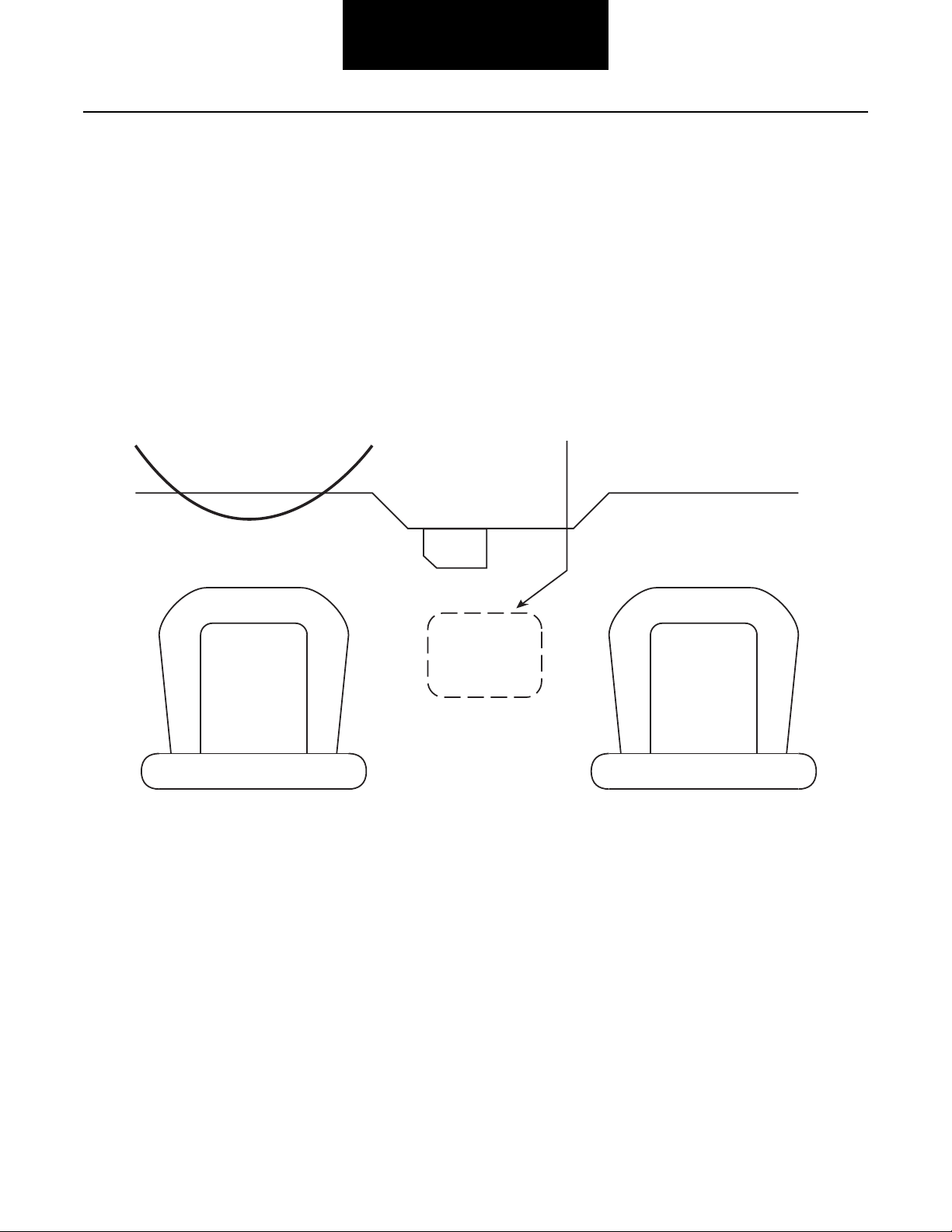
Easily accessible and removable
transmission access plate.
minimum size is 15” x 12”
DASH
Driver's
Seat
Pass
Seat
15”
12”
Vehicle Space Claim
Cab Floor Access Plate Requirements
Note: Access plate requirement applies to any vehicle configuration even though only a front engine configuration is shown.
Note: During chassis layout adequate space is required for ECA removal and maintenance.
Note: Refer to the “Transmission Component Temperature Requirements” on page 22.
Cab Floor Access Plate Requirements
1. A cab floor access plate is required for access and removal of components from the transmission top. Plate
size (minimum: 15”x12”) shall be sufficient to allow removal of the Transmission Electronic Control Unit or the
Electric Shifter.
2. Access plate requirement applies to any vehicle configuration even though only a front engine configuration is shown.
8
Vehicle Space Claim
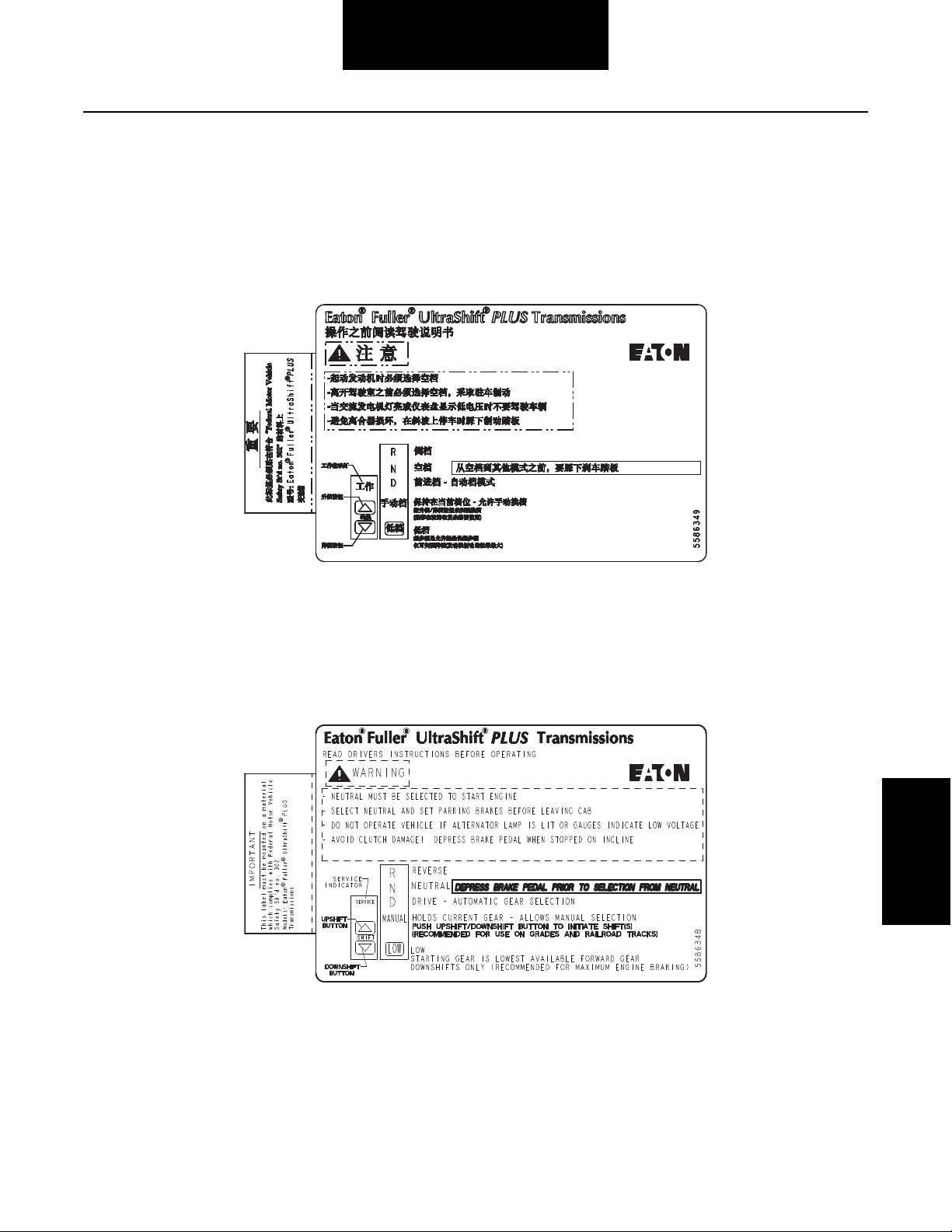
Shift Label Requirements
1. The shift label should be located in the cab so that it is visible in the driver seat.
2. Shift labels are available for shift devices in Chinese and English.
3. The OEM must match the label with the installed shift device.
Vehicle Space
Claim
9
Vehicle Space Claim
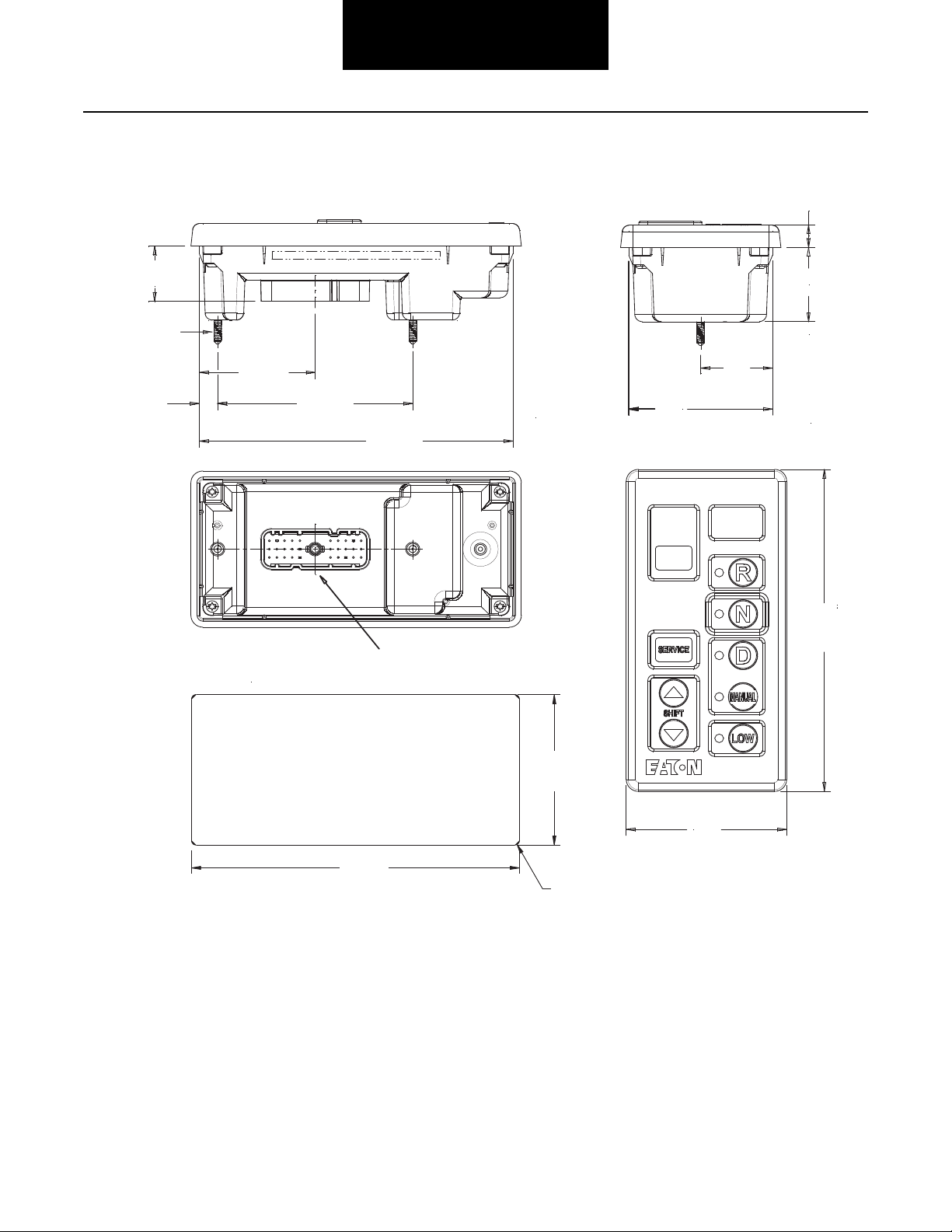
Mates with 30-way packard connector with
body #15492553 and terminals #12103881
12.2
[.48]
38.74 - 40.76
[1.525 - 1.605]
75.2
[2.96]
29.6
[1.16]
37.54
[1.478]
83.8
[3.30]
172.7
[6.80]
164.1
[6.46]
101.98
[4.015]
60.6
[2.39]
9.59
[.378]
166.62
[6.56]
PANEL CUT OUT DIMENSIONS
4X R.10 MAX
77.72
[3.06]
2X #8-32 UNC
Eaton Shift Console Space Requirements
10
Vehicle Space Claim
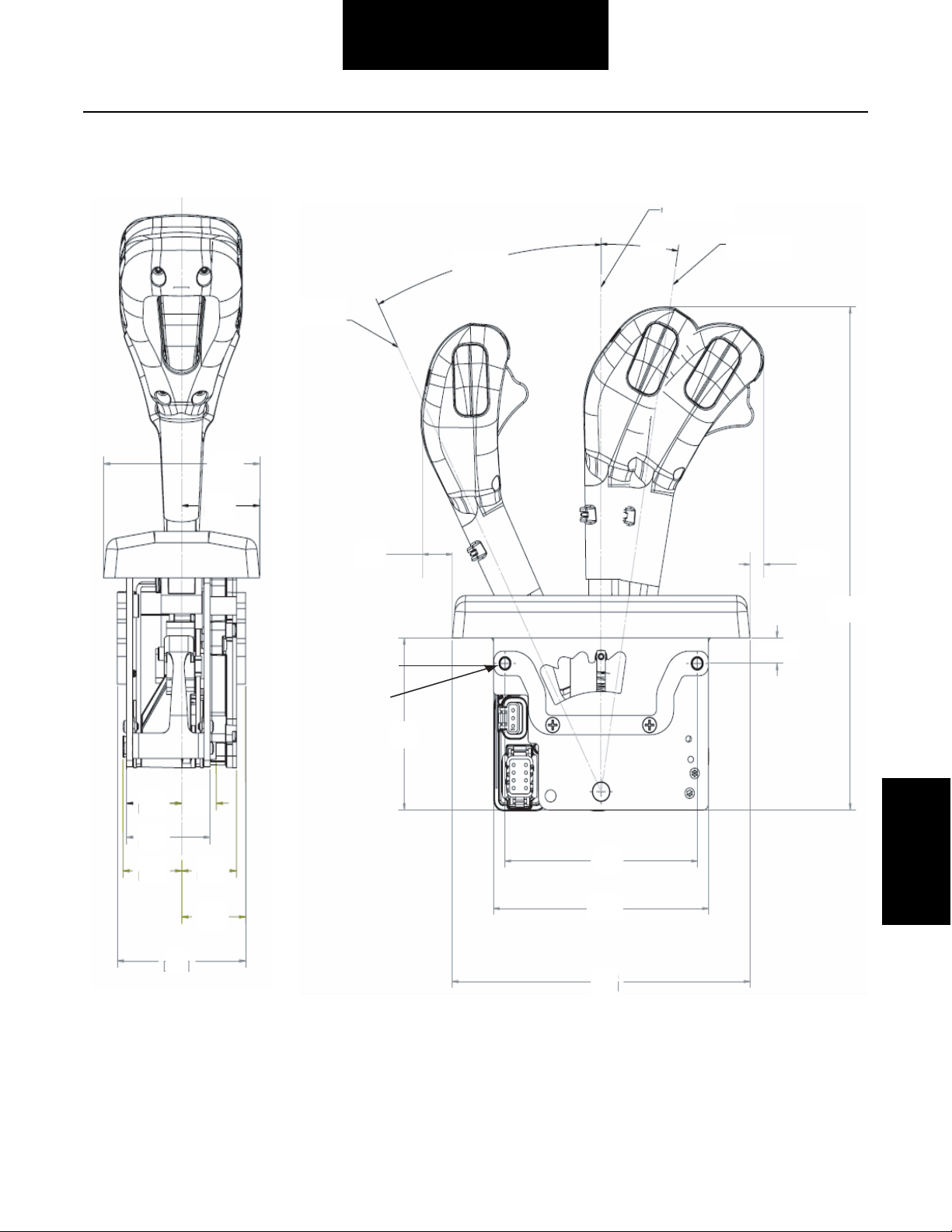
81
[3.2]
41
[1.6]
28
[1.1]18[.7]
43
[1.7]
30
[1.2]
28
[1.1]
33
[1.3]
69
[2.7]
81
[3.2]
41
[1.6]
28
[1.1]18[.7]
43
[1.7]
30
[1.2]
28
[1.1]
33
[1.3]
69
[2.7]
18
[.7]
8
[.3]
262
[10.3]
13.2 [.52]
89
[3.5]
111.3
[4.38]
124
[4.9]
173
[6.8]
18
[.7]
8
[.3]
262
[10.3]
13.2 [.52]
89
[3.5]
111.3
[4.38]
124
[4.9]
173
[6.8]
Low Gear
Position
Neutral Position
Reverse Gear
Position
27.0°
9.0°
4- M6 x 1
Use M6x1 Mounting
Screws 23-31 lb-in
[2.5-3.5 Nm]
4 Places
Eaton Shift Lever and Tower Space Requirements
Vehicle Space
Claim
11

Clutch Interface
Clutch Interface
Pilot Bearing Specifications
The OEM is responsible for the design and selection of pilot bearings to mate with our product. Eaton recommends high quality
pilot bearings procured from Original Equipment Manufacturers. Significant decrease in life may occur with the use of generic
brand pilot bearings.
The following pilot bearings are currently the minimum Eaton Clutch Division recommends. The operating temperature that the
pilot bearing sees has increased in the last several years. This creates operating conditions that are no longer acceptable to the
standard pilot bearings and grease. In addition, the life of the clutch has increased. The use of high temperature grease and Viton
seals are now mandatory to ensure adequate bearing life. Pilot bearing failure usually results in a warranty claim for drag or
clutch noise. This results in a claim against Eaton Clutch.
Below is a list of the recommended Pilot Bearings. All of these bearings have Viton seals and a high temperature grease in
addition to a C3 fit. It is acceptable to use synthetic high temperature grease and a C5 fit if desired.
If the supplier specific bearing is no longer available, contact the supplier for an equivalent alternative bearing.
Vendor Seal Type Bearing Series 6205 Bearing Series 6206 Bearing Series 6306 Bearing Series 6006
NTN Viton 6205 LLUA1/C3 6206 LLUA1 6306 LLUA1/C3 6006 LLUA1 C3/LX16
KOYO Viton 6205 2RKF-S2/C3 6206 2RU 6306 2RKF-S2/C3 -
NSK Viton 6205 DDU7/C4 ENS 6206 2RS2 6306 DDU7/C4 ENS 6006 DDWA18A C4/ENSS
SKF Viton 6205 2RS2/C3 6206 2RSJ 6306 2RS2/C3 -
FED-MOG Viton 6205 VV/C3 206 VV 6306 VV/C3 -
PEER Viton 6205-2VRLD-C3 - 6306-2VRLD-C3 6006-2VRLD-C3
12
Clutch Installation
Clutch Interface
Clutch Interface
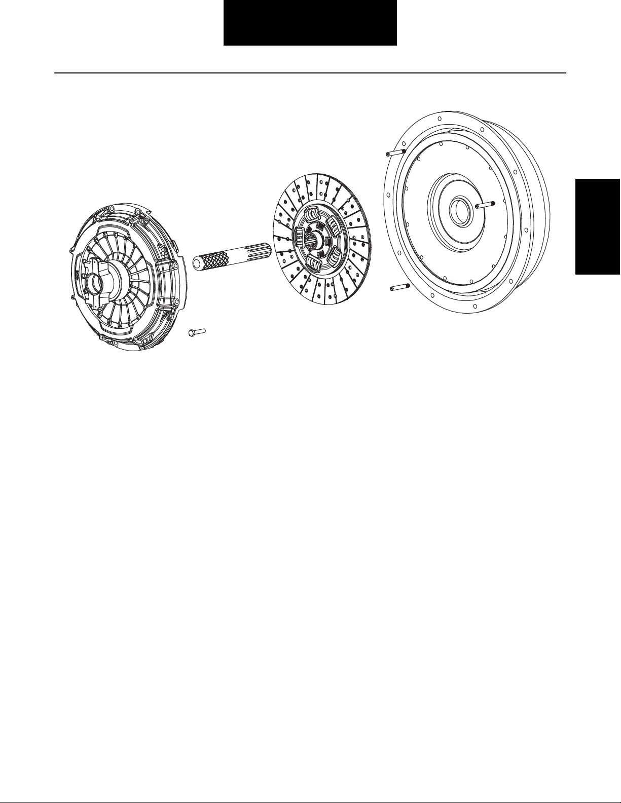
Note: Eaton supplied 395mm clutch must be used.
395 Clutch Installation Requirements
1. Install two guide studs into mounting holes.
2. Install disc onto aligning tool. Follow the orientation instructions on the disc.
3. Put aligning tool with disc into flywheel. Verify aligning tool pilot is through the pilot bearing.
4. Slide clutch assembly over aligning tool and two guide studs.
5. Install lock washers and (8) 7/16-14 x 2” grade 5 or better mounting bolts finger tight. Replace studs with lock
washers and bolts. Progressively tighten bolts in a crisscross pattern starting with a lower bolt. Torque the 395mm
to 40–50 lb-ft. [54–68 Nm].
6. Remove (4) yellow shipping bolts.
7. Remove aligning tool.
13
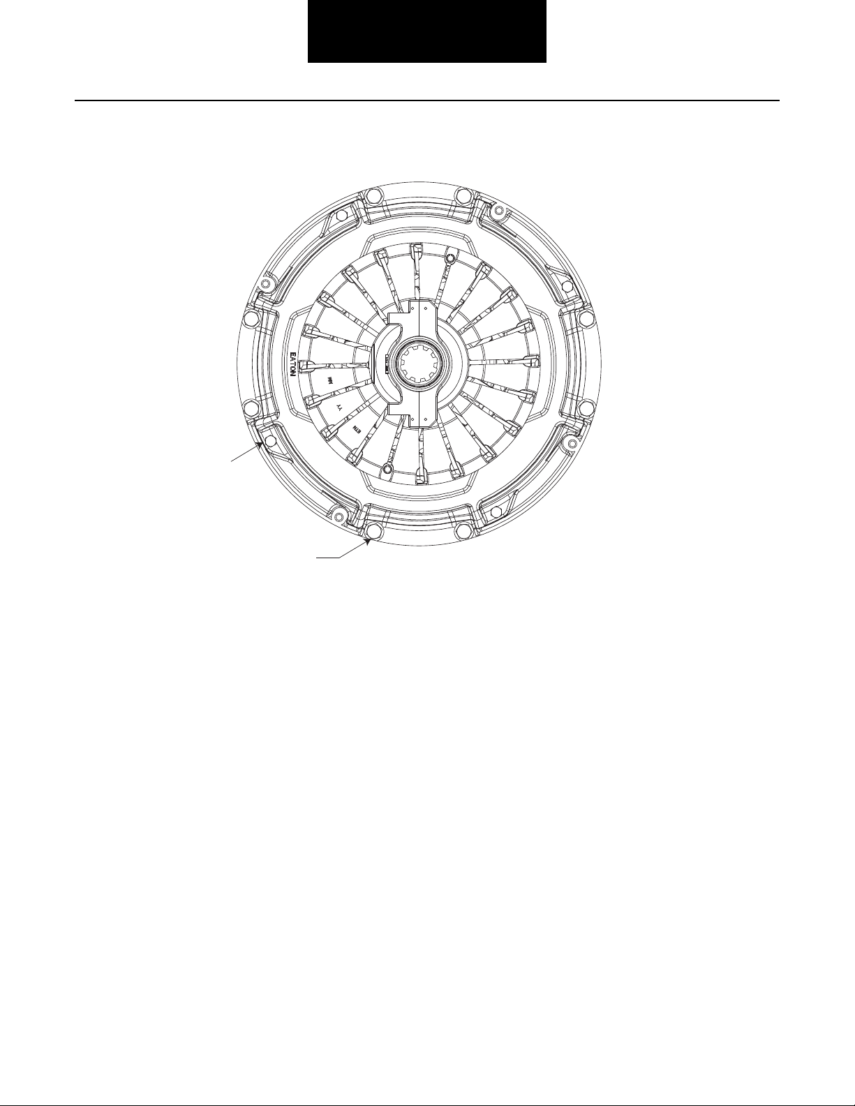
395mm Mounting Bolts and Shipping Bolts
Shipping Bolts (4)
(8) 7/16 - 14 x 2 1/4”
Torque 40-50 lbs. ft. [54-68 NM]
NOTE: Remove shipping
bolts after mounting bolts
are installed.
Clutch Interface
14
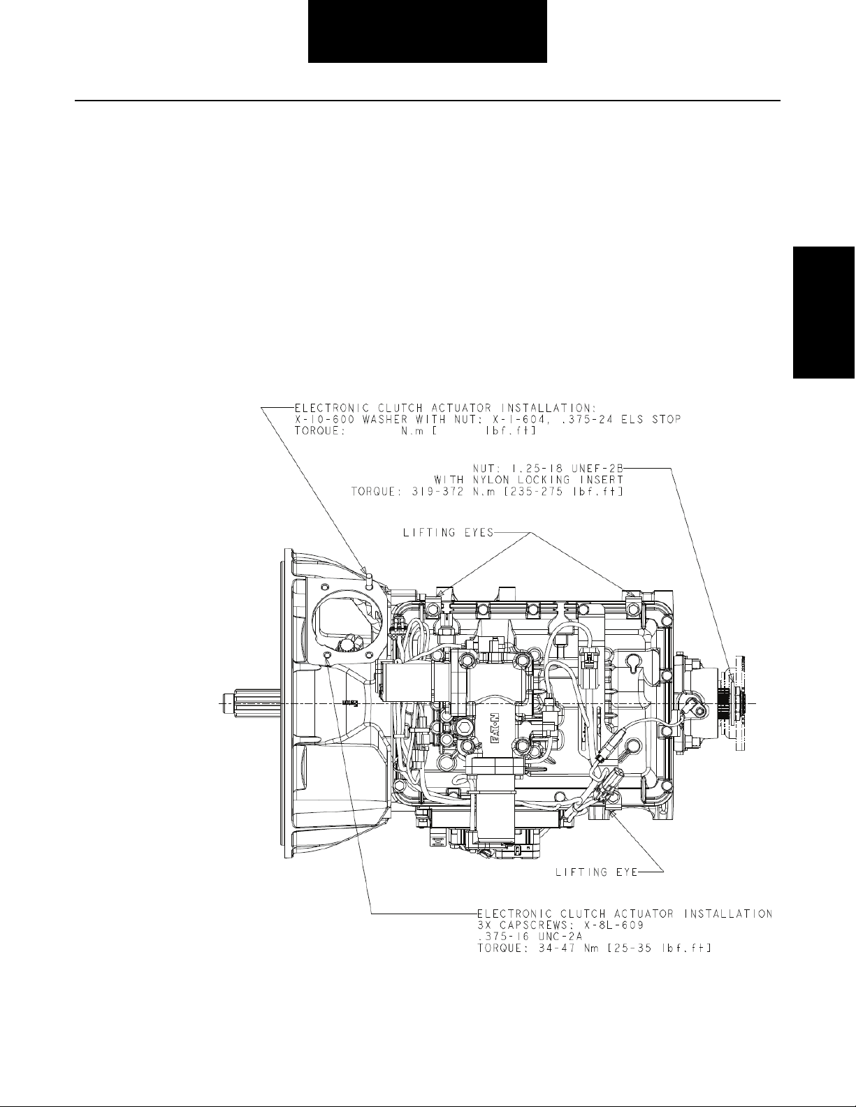
ECA Assembly Instructions
34 - 47 25 - 35
The ECA will be shipped as a loose part.
ECA Installation:
• Apply anti-seize compound to the bore of the ECA.
Clutch Interface
• The ECA will need to be rotated to line up a locating pin with a notch in the housing in order to install the ECA into the
clutch housing.
• Install the ECA onto the housing, while matching the splines of the ECA motor to the shaft.
• Install (1) 3/8”-24 nylon lock nut or nut with washer to secure the ECA to the housing. Torque to 25 - 35 ft lb (34 - 47
Nm).
• Install (3) 3/8”-16 cap screws. Torque to 25–35 ft-lb (34–47 Nm).
Clutch Interface
15

Clutch Interface
ECA Removal Instructions
If transmission removal is necessary the ECA must first be released from the clutch by one of two methods.
The first method is to use ServiceRanger:
1. Once connected with Service Ranger go to Service Routines.
2. Click the “Start” button located next to “Clutch Service Utility”. This page will give instructions for a variety of operations.
3. Select Service Position on the upper left corner of the screen, carefully follow the instructions on the screen. This will
rotate the clutch fork to the open position so the transmission can be pulled back from the engine with out damaging
the clutch.
4. Make sure the shipping bolts are installed before removing the clutch or clutch damage will occur.
The other option is to remove the ECA by using the following Instructions. Refer to the following procedure in the event the Electronic Clutch Actuator assembly requires removal and replacement:
ECA Removal:
1. Cut tie straps which secures the ECA harness (if applicable).
2. Disconnect the harness to the ECA.
3. Remove the (1) 3/8"-24 nylock nut that secure the ECA to the housing.
4. Remove the (4) 3/8"-16 capscrews that secure the ECA to the housing. Remove the ECA.
5. The ECA will need to be rotated to line up a locating pin with a notch in the housing in order to remove the ECA from the
clutch housing.
6. Make sure the shipping bolts are installed before removing the clutch or clutch damage will occur.
16

Transmission Interface
Transmission Interface
Handling
Handle the transmission carefully to avoid damage to the transmission components and surrounding vehicle components.
• Use a hoist or transmission jack that permits precise control of the transmission movement during installation.
Transmission Preparations
Note: Eaton has provided several brackets that can be used for clipping vehicle components to. ECU, sensor, and lifting eye
fasteners are not to be used for securing additional OEM brackets under any circumstances. This includes cap screws used
to fasten the shift bar housing, rear housing, bearing covers, and PTO covers. Removal of these can compromise
transmission system operation and overall system reliability.
Note: No mechanical speedometer. The rear bearing cover will offer three (3) push-in sensor openings at 3, 9, and 12 o’clock
positions. The 12 o’clock position is reserved for Eaton for the direction and speed sensor assembly. The 3 and 9 o’clock
positions are reserved for the OEM to install a speed sensor. The tone wheel has 16 teeth, as standard.
Reverse Switch
Reverse Switch Option
Reverse switch opening is standard on all medium-duty Eaton transmissions. The transmission will be shipped with plug this
opening, unless a switch is ordered by the OEM and pre installed by Eaton.
Reverse Switch
Location: Opening is located at the right front corner of the shift bar housing. See top view drawings for location.
Switch type: Normally open ball type switch. See Electrical System Interface for electrical requirements.
Thread size: 0.5625-18 UNF-2B.
Transmission
Interface
Mating Connector: Options are screw terminals or Weather Pack.
17

Transmission Interface
Mounting Transmission to Engine
Use the two transmission lifting eyes provided. The lifting eye position shall not be changed on the transmission. Do not remove
the Electric Shifter at any time.
• Use a two point lift chain or transmission jack with a minimum capacity of 1500 lbs.
• Inspect the engine to transmission mating surfaces for damage or debris prior to installation. Make sure the engine
flywheel housing face, transmission clutch housing face, input shaft, etc. are free of paint, debris, rust, and any type of
damage before installation.
• The transmission is shipped in gear until the vehicle is powered up with the key switch. Use a Pull-to-Neutral-Box to
disengage the transmission or rotate the axles to align the transmission prop shaft.
• Input Shaft To Clutch Alignment - the transmission is shipped from Eaton with the transmission in gear. The
transmission shall be in gear in order to rotate the input shaft by turning the output shaft/yoke. The transmission will
automatically reset to the neutral position as soon as the vehicle is powered up (key switched on). In the event that the
transmission is not received in gear, the input shaft will have to be manually indexed to mate up with the clutch splines.
• Adjust the lift chain or transmission jack to obtain the same relative angle as the engine. The face of the engine flywheel
housing and the face of the transmission clutch housing shall be parallel during installation. Rotate the output shaft/
yoke while sliding the input shaft into the clutch to line up the splines. If the transmission is properly aligned and the
clutch splines are properly aligned, very little force is required to slide the input shaft through the clutch and into the
pilot bearing.
• If interference is encountered, move the transmission away from the engine to investigate the cause. The use of
excessive force to overcome misalignment may cause damage to the transmission input shaft and the clutch.
• The clutch/yoke will remain in the released position during the entire transmission installation. At key on the ECA will
rotate the clutch/yoke to its proper position.
• Once the transmission is seated against the engine flywheel housing, align the clutch housing bolt holes with the engine
flywheel housing bolt holes and install all capscrews and tighten finger tight.
Note: The clutch housing shall be flush against the engine flywheel housing before tightening any capscrews. Do not
use the capscrews to seat housing.
Note: Do not tighten any mounting capscrews until all capscrews have been installed and are finger tight. Do not
remove the transmission support chain or jack until all mounting bolts have been tightened.
• The ECA and ECA cover will be shipped as a loose part to the OEM. This requires the OEM to install the ECA after the
transmission has been attached to the engine.
Using Rear Supports
Transmission rear supports are required for all Eaton UltraShift PLUS PV model installations that have a Telma retarder. The OEM
is responsible for nodal and rear support design. Refer to OEM for rear support fastener torque specifications.
18
Transmission Interface
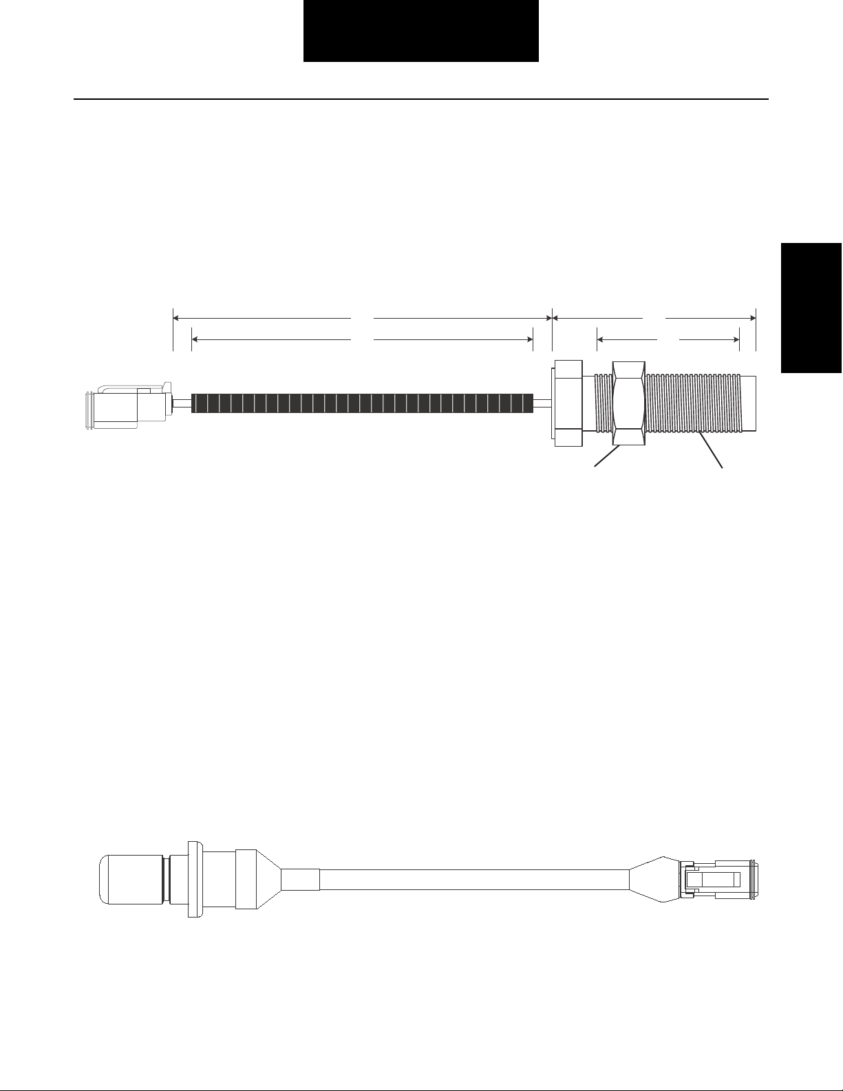
Eaton Part Number 4308074
JAM NUT
3/4" - 16NC
SENSOR
3/4" - 16UNC
5.00
4.50
2.72
1.95
DT06-2S-EP06
1
P/N 4306660
ECA Engine Speed Sensor Requirements
The OEM is required to install a dedicated engine speed sensor in this product. The use of the J1939 data bus engine speed
signal is not a substitute for this sensor.
The ECA engine speed sensor is directly connected to the ECA and mounted in the engine flywheel housing.
Note: The ECA Engine Speed Sensor requires a port in the engine flywheel housing. The preferred location of the port is either
between 3 and 5 o'clock or 7 and 9 O'clock positions, for serviceability and to prevent road debris damage.
Transmission
Interface
Threaded Engine Speed Sensor Installation Requirements
• Thread speed sensor into the engine bellhousing until it touches the flywheel then back sensor out approximately 1/2
turn to set gap.
• Set gap between sensor and flywheel to 0.055 inches +/- 0.020".
• Hold the sensor in place and tighten the 3/4"-16 jam nut to 15 lbs.ft. [20.3 Nm].
• Connect engine speed sensor connector to the mating connector on the transmission and fasten harness to the
ECA cover.
Push in Engine Speed Sensor Installation Requirements
• Install push in speed sensor and secure by proper means that sensor shall not rotate or vibrate.
• Gap between sensor and flywheel must be 0.055 +/- 0.020”.
• Connect engine speed sensor connector to the mating connector on the transmission and fasten harness to the
ECA cover.
19

Transmission Interface
Lubrication Requirements and Specifications
Eaton UltraShift PLUS PV Transmission Gear Box Lubrication Requirements
Eaton requires the use of a transmission lubricant that meets PS-164 rev 7 specification.
A list of approved lubricants and suppliers can be found in the Approved Lubricant Supplier Manual, TCMT0020.
Not using the required lubricant will result in degraded performance and shortened life of the product. Refer to the Lubrication
Manual, TCMT0021, for the latest information regarding lubrication requirements.
Note: Eaton recommends the use of Eaton Roadranger Lubricants. Roadranger SAE 50 Synthetic Lubricant and Eaton PS-164
rev 7 are the only approved synthetic lubricants.
Note: Failure to adhere to Eaton installation requirements may affect the transmission performance and / or warranty coverage.
Transmission Gear Box Required Lubricant
Eaton Roadranger SAE 50 Synthetic Lubricant
or PS164 Rev 7 approved lubricant
Warnings and Cautions
• Before working on a vehicle, place transmission in neutral, set brakes, and block wheels.
• Do not introduce additives and / or friction modifiers. Additives of any kind added later to the oil can result in
unpredictable consequences. No liability of any kind will be accepted by Eaton for any damage resulting from the use
of such additives.
• Do not mix lubricants of different grades.
• Use clean containers when transferring lubricant from the bulk storage to the transmission. Containers used for
antifreeze or water should be cleaned prior to use.
• Do not re-use lubricant.
• Failure to use the required lubricant will affect the transmission performance and the warranty coverage.
• SAE 15W-40 viscosity grades are not allowed in Eaton transmissions.
Operating Temperatures
Transmissions must not be operated at temperatures above 250 °F (121 °C.) Operation at temperatures above 250 °F (121 °C)
causes loaded gear tooth temperatures to exceed 350 °F (177 °C) which will ultimately destroy the heat treatment of the gears.
The following conditions in any combination can cause operating temperatures over 250 °F (121 °C.)
• Operating consistently at high loads / slower speeds
• High ambient temperatures
• Restricted air flow around transmission
• Exhaust system too close to the transmission
20
Transmission Interface
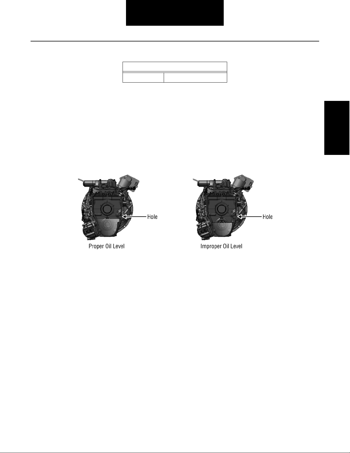
Transmission Oil Level
Transmission Capacity (Approximate)
PV 20.75 pints (9.8 liters)
1. Place vehicle on level ground.
2. Turn engine off.
3. Remove fill hole plug.
4. Lubricant must be level with the bottom of the fill hole (+/- 3mm).
5. Reinstall the fill hole plug and torque to recommended torque value.
6. Clean off any oil residue.
Make sure that the transmission lubricant is level with the bottom of the fill opening (+/-3mm).
Note: Being able to reach the lubricant with your finger does not indicate that the lubricant is at the proper level.
(On heavy-duty transmissions, one inch of lubricant equals about nine pints of oil.)
Transmission
Interface
DO NOT remove the Electric Shifter (XY Shifter) to fill the transmission with oil. Transmission must be filled through the fill hole.
21
Transmission Interface
Transmission Component Temperature Requirements
The temperature limit for all electrical and air system components is 250 °F (121 °C). Do not exceed. If sufficient air gap between
the heat source and these transmission components cannot be achieved, the OEM must provide proper methods of heat
shielding to ensure this limit is not exceeded. The components and systems to be protected would include, but not limited to, the
Shift Motors, Sensors, Solenoids, Inertia Brake, Wire Harness, Transmission Controller, ECA, and the Transmission Case.
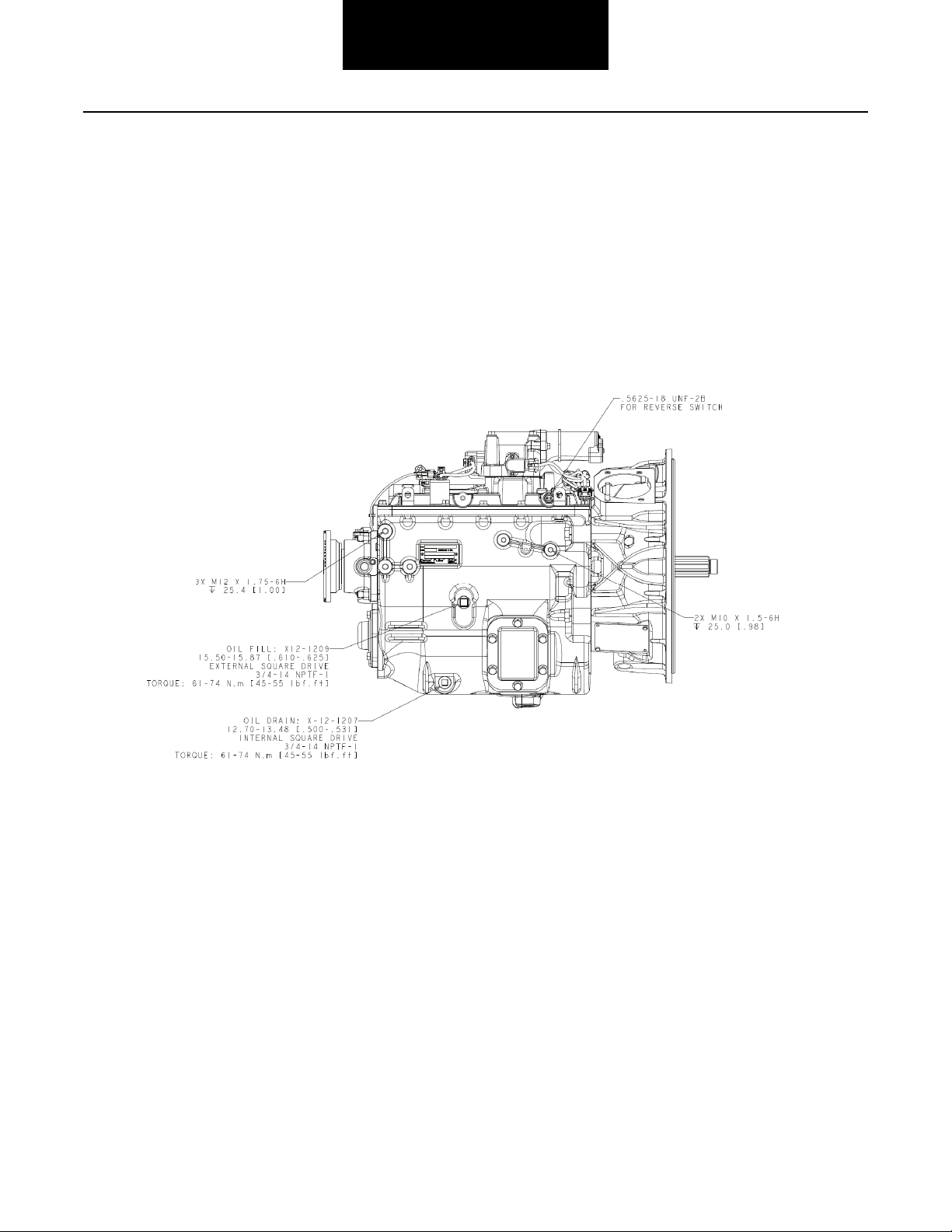
Right Side View
22
Top View
34 - 47 25 - 35
Transmission Interface
Transmission
Interface
23

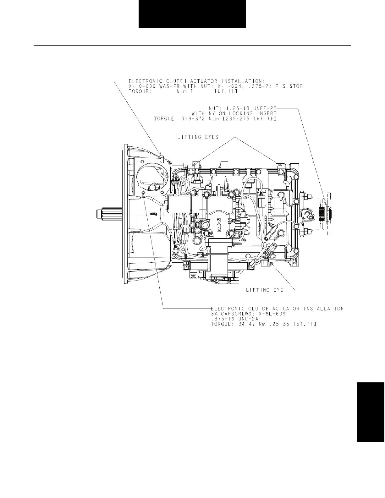
Left Side View
Transmission Interface
24
 Loading...