

Eaton NRX Series, UL489 Series Instruction Leaflet
Effective July 2016
Supercedes March 2011 Series NRXInstruction Leaet IL01301044E
Series NRX - installation and removal
instructions for drawout cassette
primary IP20 safety shutters
Instructions apply to:
UL489 series NRX RF frame
IEC IZMX40
• WARNING
(1) ONLY QUALIFIED ELECTRICAL PERSONNEL SHOULD BE PERMITTED TO WORK
ON THE EQUIPMENT.
(2) ALWAYS DE-ENERGIZE PRIMARY AND SECONDARY CIRCUITS IF A CIRCUIT
BREAKER CANNOT BE REMOVED TO A SAFE WORK LOCATION.
(3) DRAWOUT CIRCUIT BREAKERS SHOULD BE LEVERED (RACKED) OUT TO THE
DISCONNECT POSITION.
(4) ALL CIRCUIT BREAKERS SHOULD BE SWITCHED TO THE OFF POSITION AND
MECHANISM SPRINGS DISCHARGED.
FAILURE TO FOLLOW THESE STEPS FOR ALL PROCEDURES DESCRIBED IN
THIS INSTRUCTION LEAFLET COULD RESULT IN DEATH, BODILY INJURY, OR
PROPERTY DAMAGE.
• WARNING
THE INSTRUCTIONS CONTAINED IN THIS IL AND ON PRODUCT LABELS HAVE TO
BE FOLLOWED. OBSERVE THE FIVE SAFETY RULES:
– DISCONNECTING
– ENSURE THAT DEVICES CANNOT BE ACCIDENTALLY RESTARTED
– VERIFY ISOLATION FROM THE SUPPLY
– EARTHING AND SHORT-CIRCUITING
– COVERING OR PROVIDING BARRIERS TO ADJACENT LIVE PARTS
DISCONNECT THE EQUIPMENT FROM THE SUPPLY. USE ONLY AUTHORIZED
SPARE PARTS IN THE REPAIR OF THE EQUIPMENT. THE SPECIFIED
MAINTENANCE INTERVALS AS WELL AS THE INSTRUCTIONS FOR REPAIR AND
EXCHANGE MUST BE STRICTLY ADHERED TO PREVENT INJURY TO PERSONNEL
AND DAMAGE TO THE SWITCHBOARD.
Instruction Leaet IL01301044E
Effective July 2016
Series NRX - installation and removal
instructions for drawout cassette
primary IP20 safety shutters
ote:N The content of this IL applies to both PXR and Digitrip equipped breakers.
Appearance of product may vary.
Section 1: General information
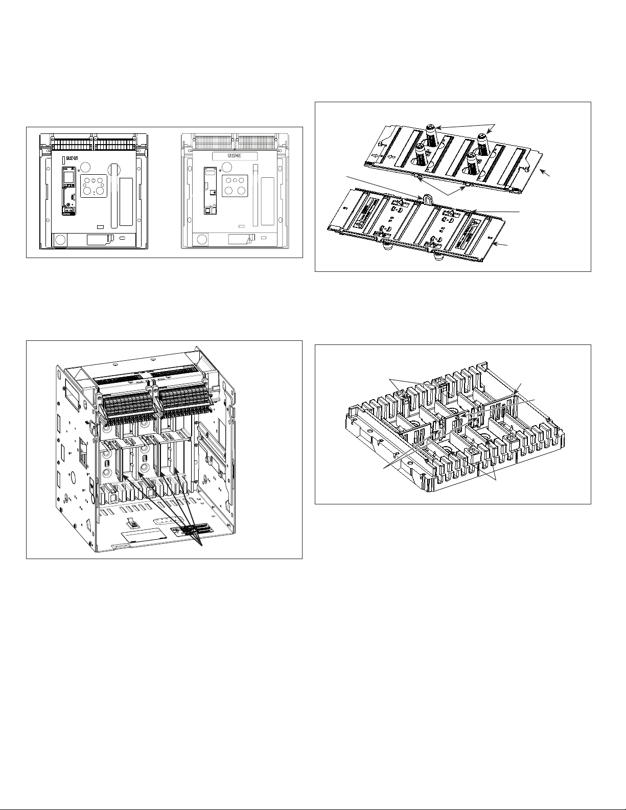
Cassette safety shutters are insulating type shutters tested to IP20
protection. They operate automatically to cover a cassette’s fixed
primary contacts when the breaker is not in the CONNECT position
(Figure 1). Provisions are provided for padlocking the shutters in the
closed position.
Three-pole shown in CLOSED position
Spring retainers
Padlock
hole
Figure 2.
Mounting tabs
Shutter assembly
Shutter assemblies.
Shutter
assembly
(up side down)
Retainer
edge
(right side up)
The two interchangeable shutter assemblies are installed in the rear
backplane (Figure 3). The backplane is shown here removed from
its cassette for clarification purposes only. Become familiar with the
cassette’s rear backplane.
Three-pole shown
Mounting tab slots
(2 on each side)
Backplane
center
divider
Padlock hole
Fixed primary contacts
Figure 1. Drawout cassette (front view, shutters open).
A complete drawout cassette shutter installation is comprised of two
duplicate, already assembled, shutter assemblies (Figure 2). Become
familiar with the shutter assemblies provided.
levers (2 on
Figure 3.
Retainer
each side)
Rear backplane only.
Spring retainer
pocket
2
EATON www.eaton.com
 Loading...