

Eaton SI-2-NA Installation Manual
Installation Instructions
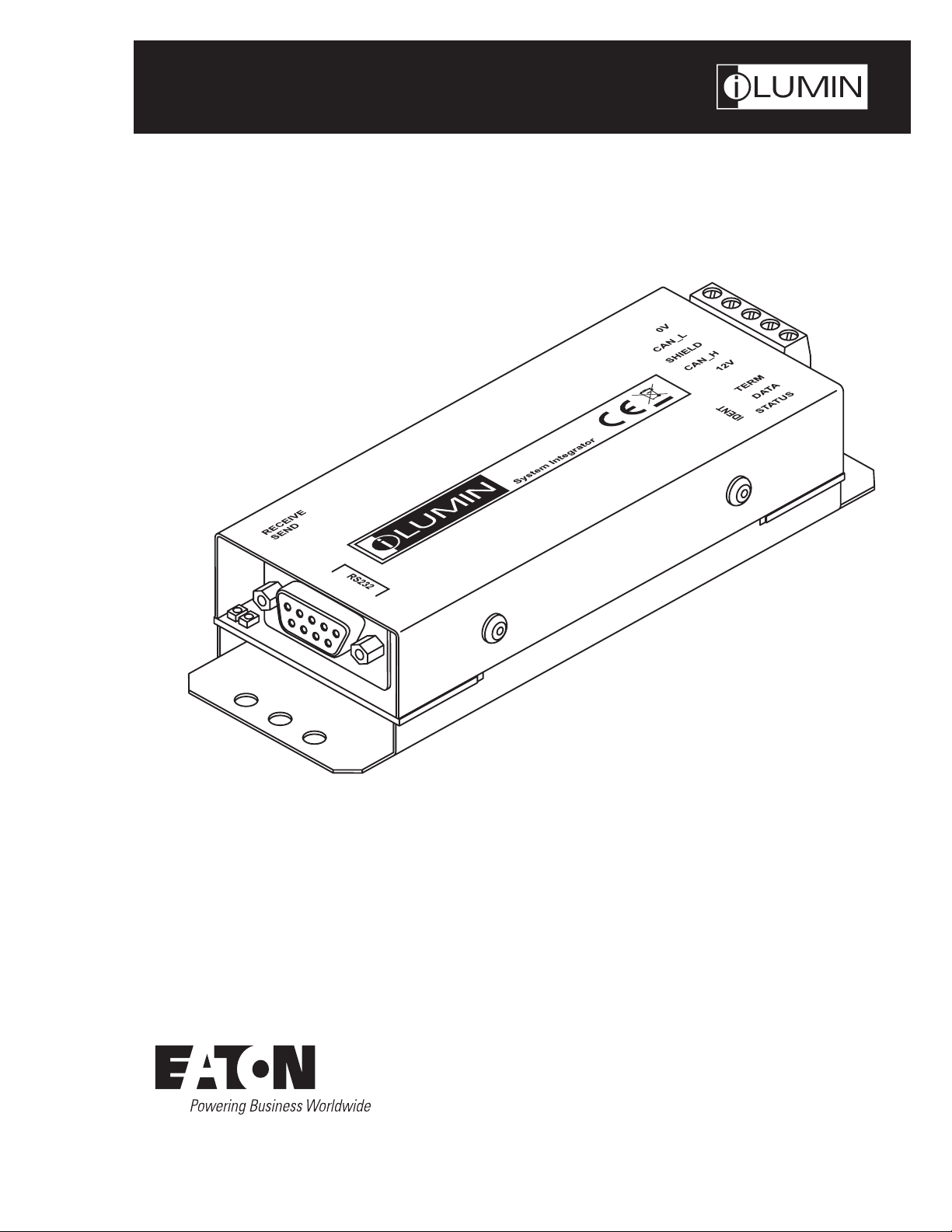
SI-2-NA – System Integrator
Model # SI-2-NA
A
SI-2-N
INS #

Contents
Contents
Description Page
Introduction ...................................................................3
Welcome ...................................................................3
Supplied parts ...............................................................3
Dimensions .................................................................3
Ambient atmosphere requirements ............................................... 3
Connections ................................................................... 4
iCANnet wiring ............................................................... 4
iCANnet announce button ......................................................4
iCANnet termination ..........................................................4
Serial device connection .......................................................5
Operation indicators ........................................................... 5
Programming ..................................................................6
Adding the SI-2-NA to iCANsoft ................................................. 6
The SI-2-NA configuration window ...............................................6
Viewing SI-2-NA details in iCANsoft ..............................................6
RS232 communication settings ..................................................7
Startup action ................................................................8
Input strings ................................................................. 9
Input actions ............................................................... 10
Output strings .............................................................. 11
Output actions .............................................................. 12
Sequences ................................................................. 13
Diagnostics ................................................................14
Appendix 1 ..................................................................15
ASCII Virtual Control Messages ................................................. 15
2
SI-2-NA – System Integrator
Introduction
Introduction
Welcome
The SI-2-NA System Integrator provides a vital link point
between any iCANnet network and a third party device
such as an audio visual unit. The compact SI-2-NA System
Integrator provides a 5-way connector block at one end for
the iCANnet link and a 9-pin D-type female socket at the
other end for the RS232 serial connection to the third party
device.
Using the intuitive iCANsoft application, you can program
the SI-2-NA to search for particular actions or messages
received from other control units attached to the iCANnet
network. When a received action or message matches a
stored template, the SI-2-NA will send a control message to
the device connected via the serial port.
Similarly, the SI-2-NA also monitors messages being sent
back from the connected serial device and when any of
those messages match those stored within its memory, a
range of actions can be triggered on the iCANnet network.
The SI-2-NA System Integrator can store up to 100 input
and output messages together with their related actions.
Additionally, the SI-2-NA can store up to 16 sequences, each
of which can comprise up to 128 separate steps to allow
multiple actions to be triggered by a single command.
Supplied Parts
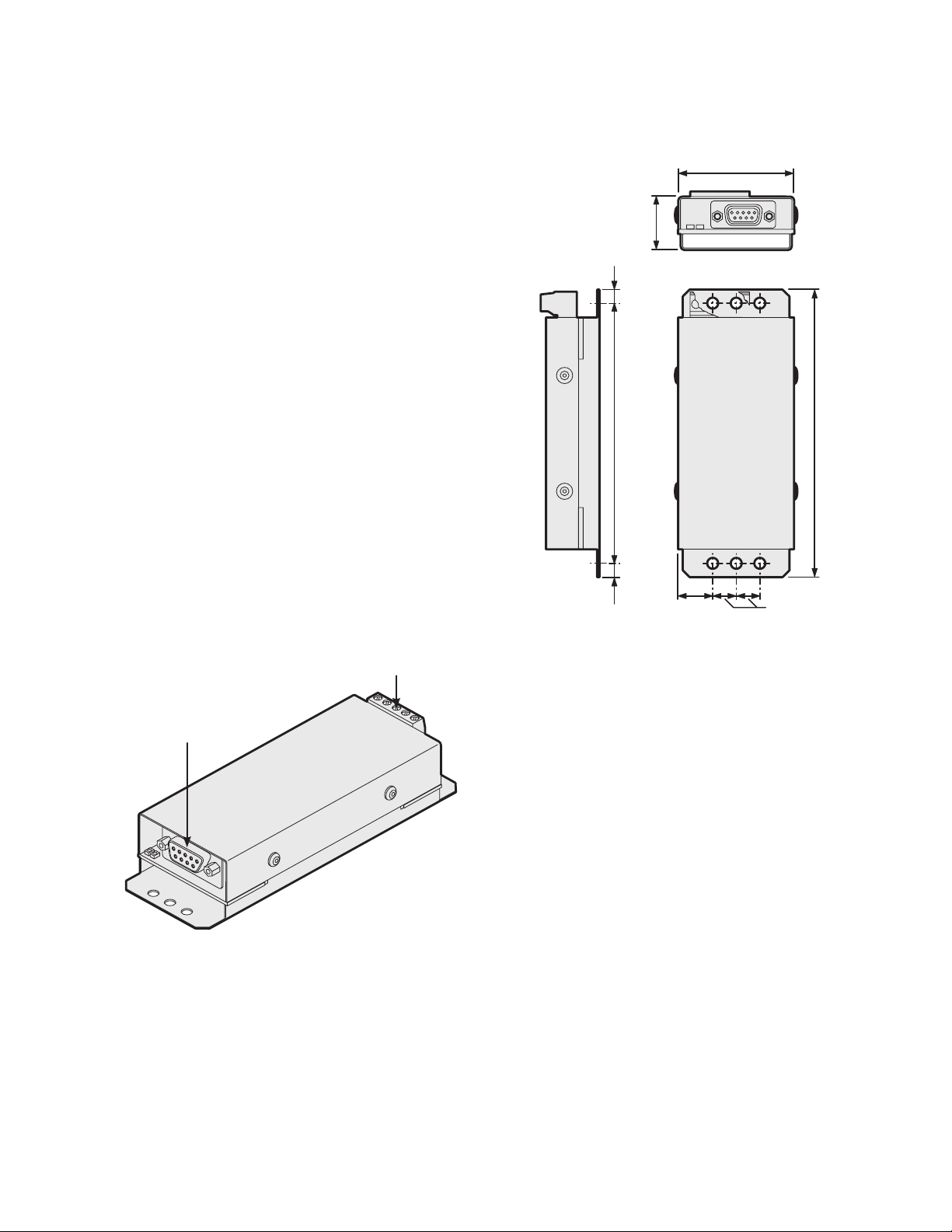
Dimensions
0.9 in.
(23 mm)
0.24 in.
(6 mm)
4.40 in.
(112 mm)
0.24 in.
(6 mm)
0.6 in.
(15 mm)
1.97 in.
(50 mm)
4.88 in.
(124 mm)
0.4 in.
(10 mm)
Serial connection
to device
iCANnet connection to network
ote:N All mounting holes are 4mm (0.15 in.) diameter. The
two outer holes at either end allow you to attach the
unit using plastic ties.
Ambient atmosphere requirements
Temperature 00C to +400C (320F to 1040F)
Humidity 0 to 95% non-condensing
SI-2-NA – System Integrator
3
Connections
Connections
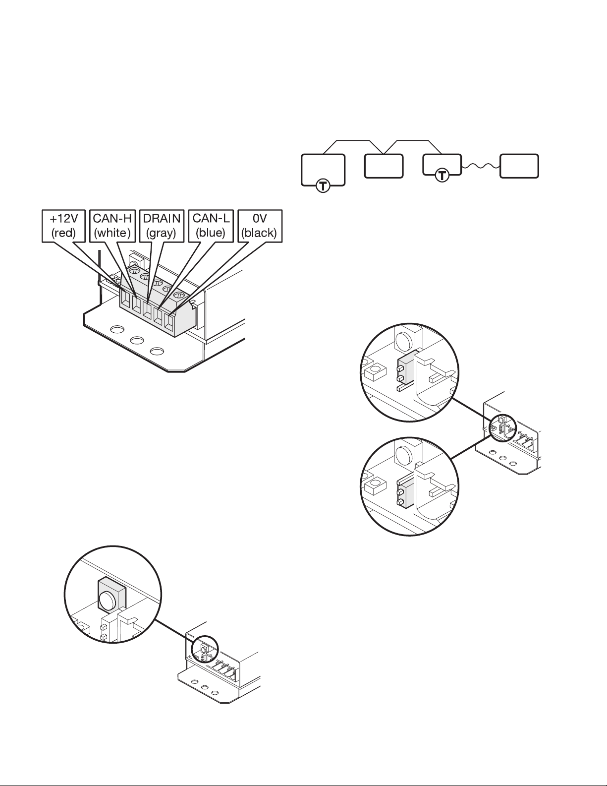
iCANnet wiring
Cable connections to the iCANnet network are made to a
removable 5-way connector block located at one end of the
SI-2-NA unit:
Cable type: Cooper LC or Belden 1502
Cooper
LC cable
iCANnet termination
The iCANnet link is a ‘daisy chain’ protocol that requires
termination on the devices located at either end of the
iCANnet chain.
iCAN
Device
The SI-2-NA unit is supplied with termination enabled as
standard. If it is not connected as an end device in the
iCANnet chain, you need to disable termination.
ote:N The connection to the serial device is treated
separately and has no impact on whether or not
the SI-2-NA should be terminated.
To disable SI-2-NA termination, move the jumper from the
lower two pins to the upper two pins, as shown here:
Termination OFF
iCAN
Device
SI-2-NA
Serial
Device
Each Source Controller can power up to 10 wallstations/
devices. These devices must be within 1,000 ft of the
Source Controller. For devices further from a Source
Controller, add a 15 Vdc power supply. If there are more
than 100 devices on the iCANnet segment use a BN-2-NA
to repeat the signal.
iCANnet announce button
The SI-2-NA unit features a small button adjacent to the
iCANnet connector which can be used to add the device to
an iCANnet network. When pressed, the SI-2-NA will send
an announcement message across the iCANnet network.
Please see the section ‘Adding the SI-2-NA to iCANsoft’ for
more details.
Termination ON
4
SI-2-NA – System Integrator
Connections
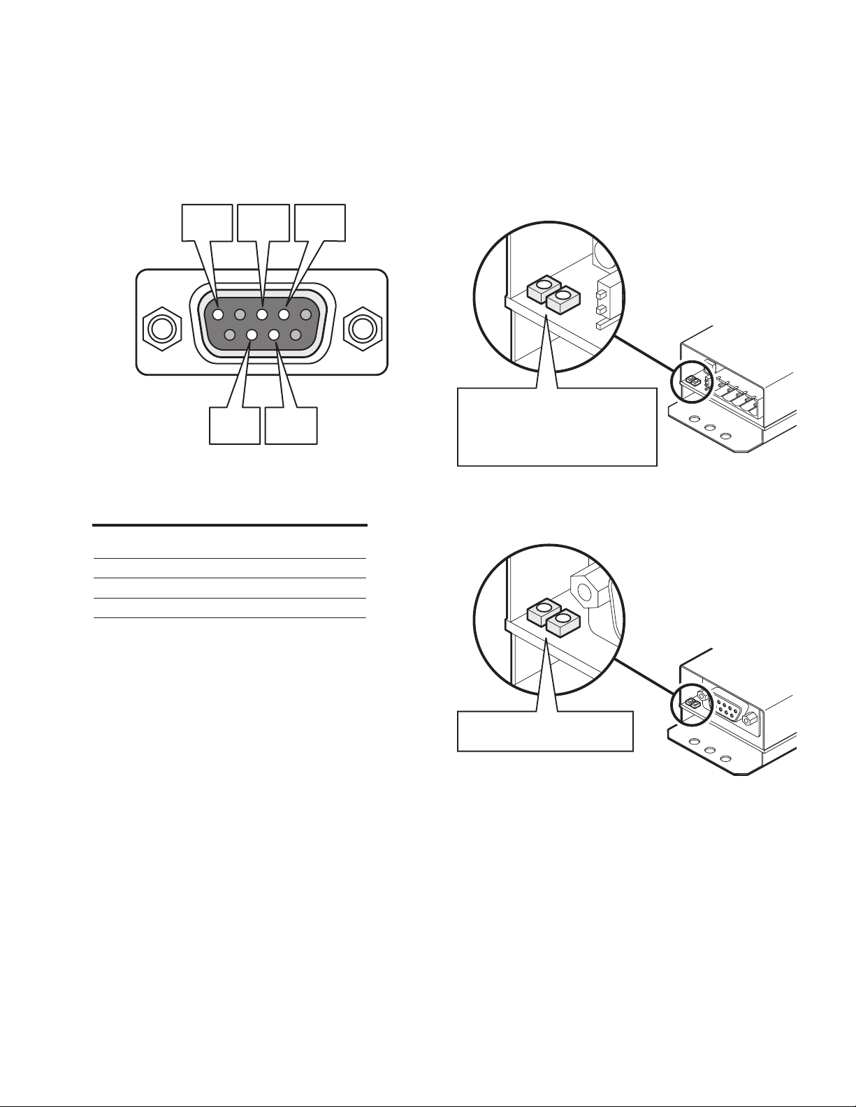
Serial device connection
The SI-2-NA unit provides an RS232 link via a standard 9-pin
D-type female connector. The SI-2-NA uses five pins of the
D-type connector as shown below:
GND
(pin 5)
RxD
(pin 3)
RTS
(pin 8)
The various serial communication parameters used by
the SI-2-NA serial port are all fully configurable using the
iCANsoft application:
Baud rate 1200, 2400, 4800, 9600, 19200,
Data bits 7 or 8
Stop bits 1 or 2
Parity None, Reserved, Even or Odd
Handshaking Enabled or Disabled
38400, 57600 or 115200
TxD
(pin 2)
CTS
(pin 7)
Operation indicators
The SI-2-NA unit has a red and green indicator at either end
to assist with configuration and troubleshooting.
At the iCANnet end
Green flashing: Normal operation
Red flashing: Traffic being sent
and/or received
Red on: iCANnet error
At the RS232 end
Green: RS232 data received
Red: RS232 data sent
SI-2-NA – System Integrator
5
Programming
Programming
This section provides details about programming items
specific to the SI-2-NA system integrator within the
iCANsoft application. For details about the general use of
iCANsoft, please refer to the System manual.
Adding the SI-2-NA to iCANsoft
Once the SI-2-NA System Integrator has been connected
to the iCANnet network, you can add it to the iCANsoft
application in any of the following three ways:
Within the iCANsoft main window, click the icon,
Within the iCANsoft main window, select ‘Tools’ >
‘Advanced Network Search’, or
On the SI-2-NA unit, adjacent to the iCANnet connector
block, press and release the small button to cause an
announcement message to be sent across the network.
ote:N Where there are multiple SI-2-NA units installed
on a network, you can use the announce button to
pinpoint the device within iCANsoft. Its entry within
the device list will appear in bold and the iCANsoft
output section will provide device number details.
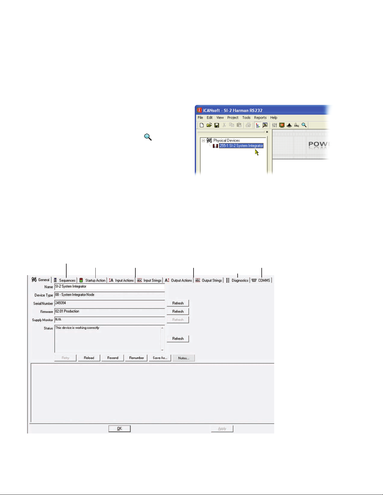
SI-2-NA configuration window
This tabbed window provides all of the options necessary to
program the SI-2-NA unit.
Viewing the SI-2-NA details in iCANsoft
Once the SI-2-NA unit has been added to the iCANsoft
application, it will appear in the devices list within the
Workspace window:
To view the configuration window for the SI-2-NA system
integrator, double click its entry within the list.
Sequences
Startup
Actions
Input Actions
and Strings
Output Actions
and Strings
Diagnostics
Communication
settings
6
SI-2-NA – System Integrator
 Loading...