

Eaton QD5, Cooper Powers Series, Cooper Power Series, 5740785B72ER User Manual
QD5 Quik-Drive voltage regulator tap-changer manual
COOPER POWER
SERIES
Voltage Regulators
MN225012EN
Effective March 2016
Supersedes S225-12-2 February 2013

QD5 QUIK-DRIVE TAP-CHANGER INSTALLATION AND MAINTENANCE INSTRUCTIONS MN225012EN March 2016
DISCLAIMER OF WARRANTIES AND LIMITATION OF LIABILITY
The information, recommendations, descriptions and safety notations in this document are based on Eaton Corporation’s
(“Eaton”) experience and judgment and may not cover all contingencies. If further information is required, an Eaton sales
office should be consulted. Sale of the product shown in this literature is subject to the terms and conditions outlined in
appropriate Eaton selling policies or other contractual agreement between Eaton and the purchaser.
THERE ARE NO UNDERSTANDINGS, AGREEMENTS, WARRANTIES, EXPRESSED OR IMPLIED, INCLUDING WARRANTIES
OF FITNESS FOR A PARTICULAR PURPOSE OR MERCHANTABILITY, OTHER THAN THOSE SPECIFICALLY SET OUT IN ANY
EXISTING CONTRACT BETWEEN THE PARTIES. ANY SUCH CONTRACT STATES THE ENTIRE OBLIGATION OF EATON. THE
CONTENTS OF THIS DOCUMENT SHALL NOT BECOME PART OF OR MODIFY ANY CONTRACT BETWEEN THE PARTIES.
In no event will Eaton be responsible to the purchaser or user in contract, in tort (including negligence), strict liability or
other-wise for any special, indirect, incidental or consequential damage or loss whatsoever, including but not limited to
damage or loss of use of equipment, plant or power system, cost of capital, loss of power, additional expenses in the use of
existing power facilities, or claims against the purchaser or user by its customers resulting from the use of the information,
recommendations and descriptions contained herein. The information contained in this manual is subject to change without
notice.
ii

QD5 QUIK-DRIVE TAP-CHANGER INSTALLATION AND MAINTENANCE INSTRUCTIONS MN225012EN March 2016
Contents
SAFETY INFORMATION
Safety information .............................................................................iv
PRODUCT INFORMATION
Introduction ...................................................................................1
Standards .....................................................................................1
General .......................................................................................1
Motor ........................................................................................1
Motor resistance ...............................................................................1
Motor capacitor ................................................................................2
Holding switch .................................................................................2
Contacts ......................................................................................3
Main stationary contacts .........................................................................3
Main movable contacts ..........................................................................3
Reversing stationary contacts .....................................................................3
Main reversing movable contacts ..................................................................4
Micro switches.................................................................................4
QD5 tap-changer operating sequence ...............................................................4
MAINTENANCE, SERVICE AND TROUBLESHOOTING .................................................5
QD5 TAP-CHANGER SCHEMATIC .................................................................. .10
QD5 TAP-CHANGER TORQUE REGUIREMENTS.......................................................13
QD5 TAP-CHANGER REVERSING MOVABLE CONTACT ASSEMBLY KIT 5740785B72ER .................19
QD5 TAP-CHANGER REVERSING NEUTRAL STATIONARY CONTACT ASSEMBLY KIT 5791646A26 ......23
QD5 TAP-CHANGER MAIN STATIONARY CONTACT ASSEMBLY KIT 5791646A24 .......................30
QD5 TAP-CHANGER VL REVERSING STATIONARY CONTACT ASSEMBLY KIT 5791646A25 ..............33
QD5 TAP-CHANGE VR REVERSING STATIONARY CONTACT ASSEMBLY KIT 5791646A27 ...............36
QD5 TAP-CHANGER MOTOR REPLACEMENT PROCEDURE KIT 57A63675100A .........................39
QD5 TAP-CHANGER MAIN MOVABLE CONTACT REPLACEMENT KIT 5740785B33 ......................46
iii
QD5 QUIK-DRIVE TAP-CHANGER INSTALLATION AND MAINTENANCE INSTRUCTIONS MN225012EN March 2016
!
SAFETY
FOR LIFE
Eaton meets or exceeds all applicable industry standards relating to product safety in its Cooper Power™ series products.
We actively promote safe practices in the use and maintenance of our products through our service literature, instructional
training programs, and the continuous efforts of all Eaton employees involved in product design, manufacture, marketing,
and service.
We strongly urge that you always follow all locally approved safety procedures and safety instructions when working around
high voltage lines and equipment, and support our “Safety For Life” mission.
Safety for life
!
SAFETY
FOR LIFE
Safety information
The instructions in this manual are not intended as a
substitute for proper training or adequate experience in the
safe operation of the equipment described. Only competent
technicians who are familiar with this equipment should
install, operate, and service it.
A competent technician has these qualifications:
• Is thoroughly familiar with these instructions.
• Is trained in industry-accepted high and low-voltage safe
operating practices and procedures.
• Is trained and authorized to energize, de-energize, clear,
and ground power distribution equipment.
• Is trained in the care and use of protective equipment
such as arc flash clothing, safety glasses, face shield, hard
hat, rubber gloves, clampstick, hotstick, etc.
Following is important safety information. For safe
installation and operation of this equipment, be sure to read
and understand all cautions and warnings.
Hazard Statement Definitions
This manual may contain four types of hazard statements:
DANGER
Indicates an imminently hazardous situation which, if
not avoided, will result in death or serious injury.
WARNING
Indicates a potentially hazardous situation which, if not
avoided, could result in death or serious injury.
CAUTION
Indicates a potentially hazardous situation which, if not
avoided, may result in minor or moderate injury.
CAUTION
Indicates a potentially hazardous situation which, if not
avoided, may result in equipment damage only.
Safety instructions
Following are general caution and warning statements that
apply to this equipment. Additional statements, related to
specific tasks and procedures, are located throughout the
manual.
DANGER
Hazardous voltage. Contact with hazardous voltage will
cause death or severe personal injury. Follow all locally
approved safety procedures when working around highand low-voltage lines and equipment.
G103.3
WARNING
Before installing, operating, maintaining, or testing this
equipment, carefully read and understand the contents
of this manual. Improper operation, handling or
maintenance can result in death, severe personal injury,
and equipment damage.
G101.0
WARNING
This equipment is not intended to protect human
life. Follow all locally approved procedures and safety
practices when installing or operating this equipment.
Failure to comply can result in death, severe personal
injury and equipment damage.
G102.1
WARNING
Power distribution and transmission equipment must
be properly selected for the intended application. It
must be installed and serviced by competent personnel
who have been trained and understand proper safety
procedures. These instructions are written for such
personnel and are not a substitute for adequate training
and experience in safety procedures. Failure to properly
select, install or maintain power distribution and
transmission equipment can result in death, severe
personal injury, and equipment damage.
G122.3
iv
Product information
QD5 QUIK-DRIVE TAP-CHANGER INSTALLATION AND MAINTENANCE INSTRUCTIONS MN225012EN March 2016
Introduction
Eaton combines more than 50 years of tap-changer
experience with the latest technology providing the most
advanced and reliable voltage regulator tap-changer in its
Cooper Power series QD5 Quik-Drive™ tap-changer. Eaton
provides the proven value customers have come to expect
from the leader. By using advanced thermal-set material
rather than Phenolic material Eaton has been able to design
in strength to meet the most demanding applications.
The design provides for an improved contact alignment
and longer contact life. The QD5 tap-changer incorporates
Cooper’s exclusive holding switch circuit, which has set the
standard for tap-changer tracking reliability.
The QD5 Quik-Drive tap-changer offers many advanced
features when integrated with Eaton's Cooper Power series
voltage regulator controls. Applications such as Preventative
Maintenances Tapping (PMT™), Duty Cycle Monitor (DCM),
and Time–ON-TAP™ features enables the unique capability
to monitoring factors that affect tap-changer life.
Read this manual first
These instructions apply to distribution voltage regulators
equipped with the QD5 tap-changer. Read these instructions
carefully before attempting maintenance on the voltage
regulator.
The equipment covered by these instructions should be
operated and serviced only by competent personnel familiar
with good safety practices. These instructions are written
for such personnel and are not intended as a substitute for
adequate training and experience in safe procedures for this
type of equipment.
The text of this instruction includes information concerning
hazards to safety, which are common to all regulators.
This safety hazard information is offered for guidance
when installing and operating the descriptive matter to
aid in preventing damage to the equipment and to advise
of possible hazards to personnel. When reading this text,
the meaning and content of these statements should be
understood and followed carefully.
Standards
ISO 9001 Certified Quality Management System
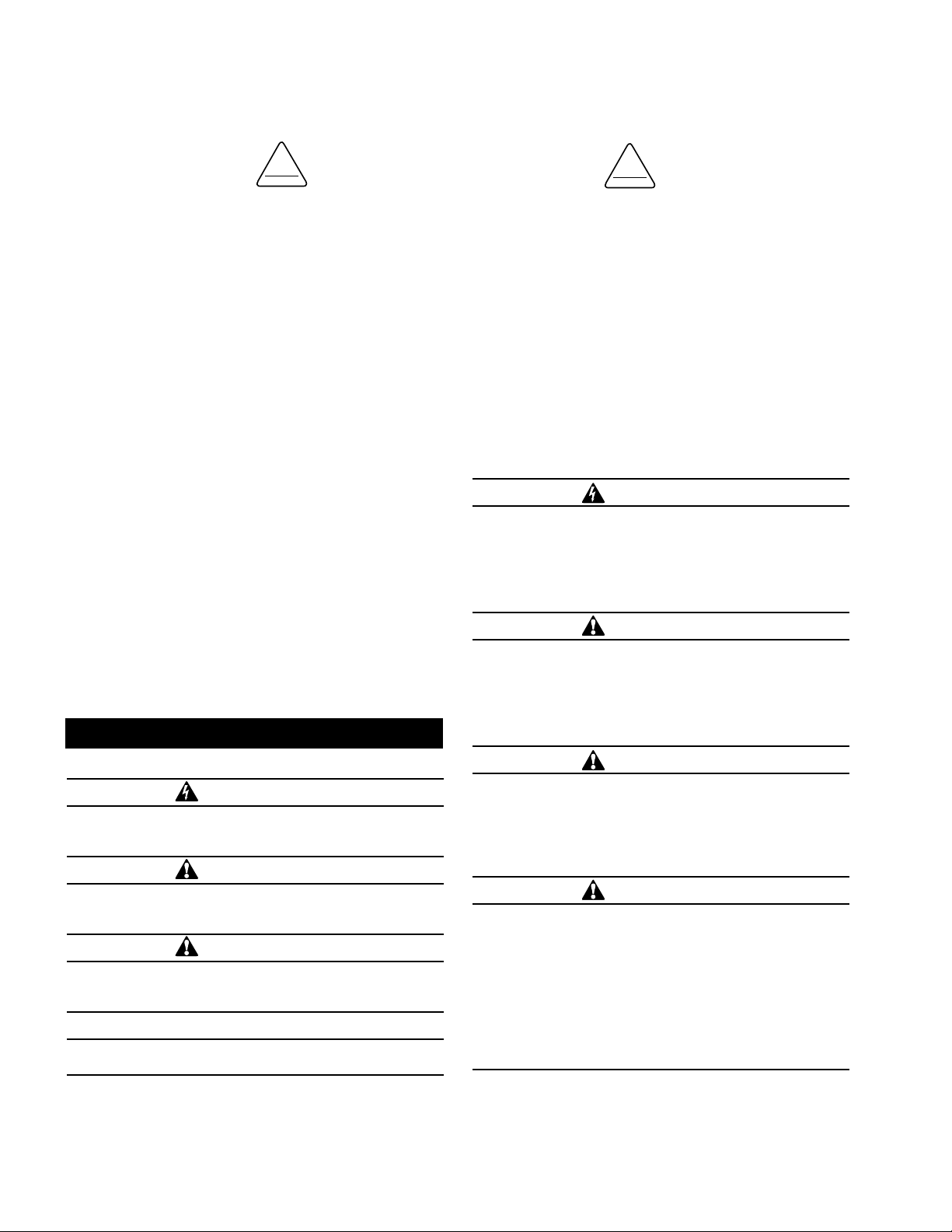
CAUTION
Do not operate the motor in air for excessive periods of
time or overheating and failure may result.
Figure 1. Motor.
General
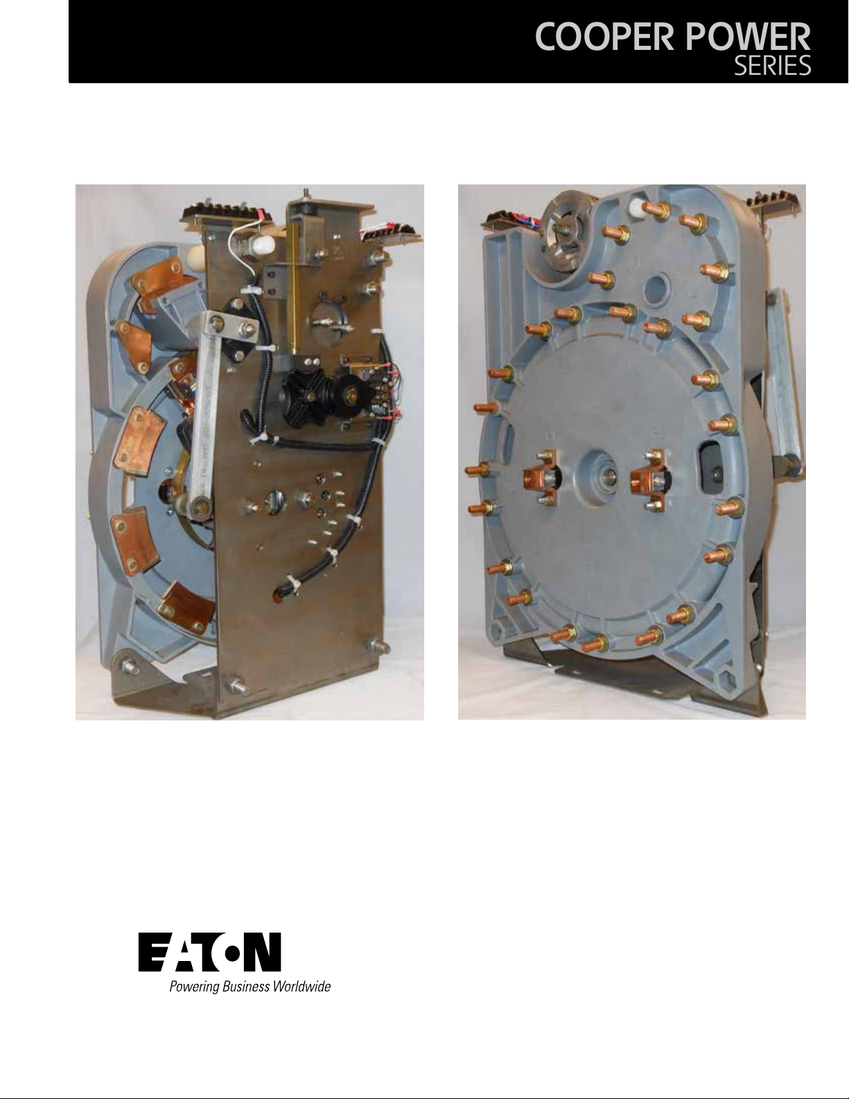
Service Information MN225012EN covers operating,
maintenance and component replacement instructions for
the QD5 Quik-Drive tap-changer in Eaton's Cooper Power
series VR-32 voltage regulators. The QD5 tap-changer
in 2003 replaced the 770 Direct Drive tap-changers for
low current application single-phase voltage regulators.
Replacing the medium direct drive model 770, 150 kV BIL,
the QD5 tap-changer like the 770 direct drive tap-changer
are used on voltage regulators with a load rating up to 328
Amps. In 2007, the original Phenolic contact board design of
the QD5 was replace by thermal-set material.
Motor
The motors for the QD5 Quik-Drive tap-changer are
permanent split capacitor type suitable for operation in both
directions of rotation at 120 Vac, single-phase, 50/60 Hz. All
components are compatible with hot transformer oil and
windings are oil cooled. The motor will carry locked–rotor
current for at least 3000 hours.
Motor resistance
To measure the motor resistance of each motor directional
winding, see the following:
Motor Ground “White Lead” to
“Blue Lead” Raise = 7.2 ohms
Motor Ground “ White Lead” to ”
Red Lead” Lower = 7.2 ohms
Raise “Blue Lead” to Lower
“Red Lead” = 13.9 ohms
1
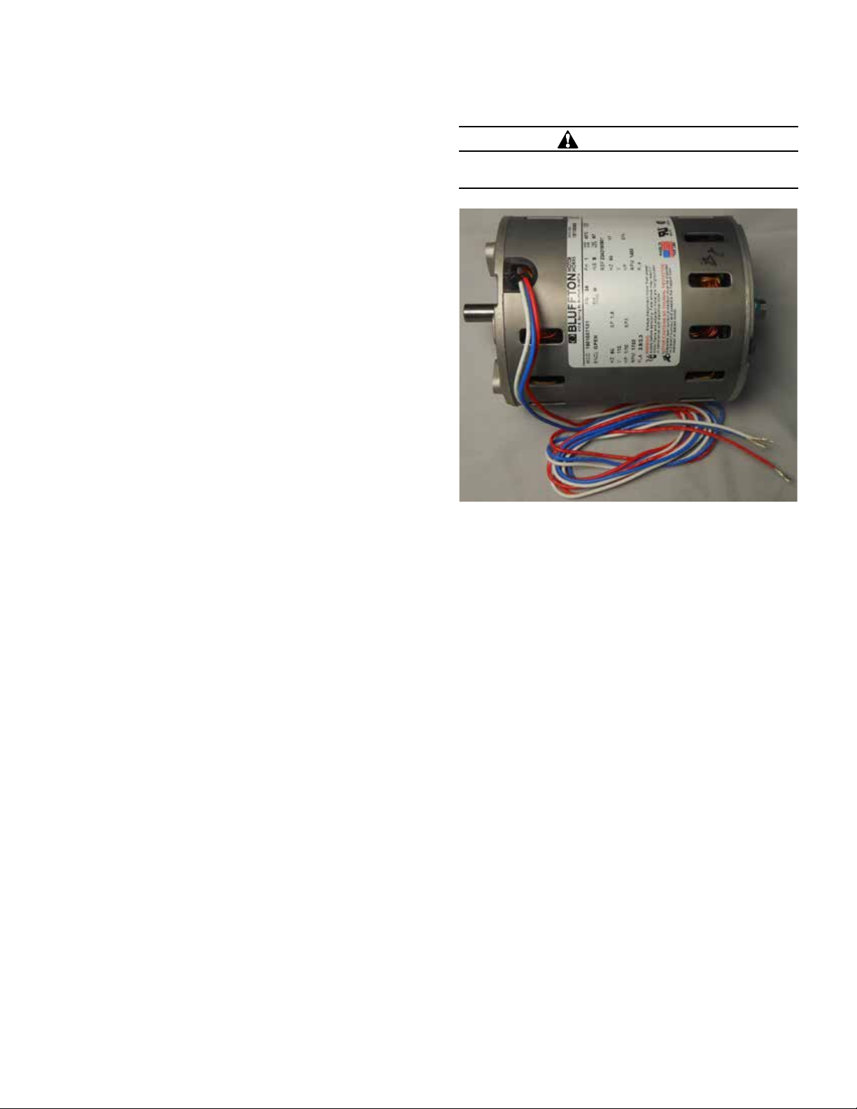
Motor capacitor
QD5 QUIK-DRIVE TAP-CHANGER INSTALLATION AND MAINTENANCE INSTRUCTIONS MN225012EN March 2016
The QD5 tap-changer motor uses a 50 μF, 440 Vac, and
100°C motor capacitor. The motor capacitor is not part of
the tap-changer assembly; it will be located in the voltage
regulator control box.
Figure 2. Motor capacitor.
Motor capacitor
Size Rating
50 μ F, 440 Vac, 100°C for 50 and 60 Hertz
It is recommended that a replacement capacitor be of the
same size and rating as was originally supplied with the unit.
Incorrectly sized motor capacitors can cause the motor to
labor and not run properly or at all; premature motor failure
will result. Tap position tracking of the voltage regulator
control will also be adversely affected by improperly sized
motor capacitors.
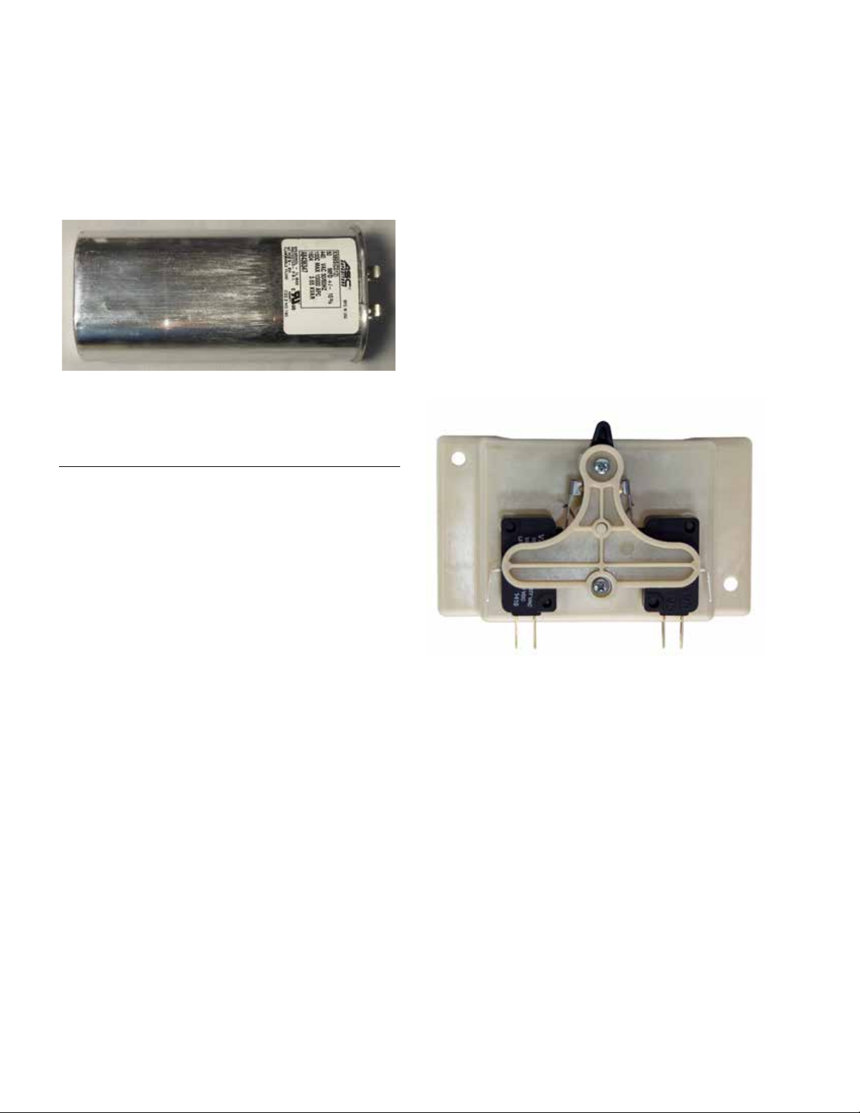
Holding switch
Eaton's tap-changers are equipped with a holding switch
to assure that a tap-changer operation is completed. This
switch also provides a repetitive and accurate opening
action causing the motor to stop the drive components
with correct alignment. A signal from the holding switch
activates the operations counter and prevents time delay
reset during a tap change. The holding switch is operated by
a pinion cam causing the holding switch lever to close in on
either the raise or lower micro switch.
If there is a problem with one of the micro switches on the
holding switch, the individual micro switch should not be
replaced. Instead, the complete holding-switch assembly
must be replaced. Replacement of an individual micro
switch can cause alignment problems which will affect
the operation of the tap-changer. Special fixtures are used
to assemble the holding-switch assembly to ensure that
alignment gap setting requirements are met.
Figure 3. Holding switch assembly.
2
Contacts
QD5 QUIK-DRIVE TAP-CHANGER INSTALLATION AND MAINTENANCE INSTRUCTIONS MN225012EN March 2016
All movable and main stationary contacts employ
copper-tungsten alloy tips at points subjected to arcing
duty. Contact points not subjected to arcing employ a
combination of EPT copper to provide a high conductivity
current path. Movable contacts are split to make contact
on both sides of mating parts and resist separation during
high current surges. Contact pressure is maintained by steel
compression springs.
Main stationary contacts
Copper-Tungsten
Arcing Tips
The main movable contact assembly is made up of a set
of two individual contact assemblies and a thermal set
material insulating arm. Each of the main movable contacts
makes contact with the main stationary contacts as the
tap changer rotates through each tap position. At least one
of the main movable contacts remains in contact with a
stationary contact at all times. The main stationary contacts
bolt to collector rings. The collector rings insert between
a set of button contacts that are able to hold a continuous
current path through all 32 steps of the tap changer and
while in neutral. The movable contact assemblies are
identical and can be used for either the right or left hand
contacts.
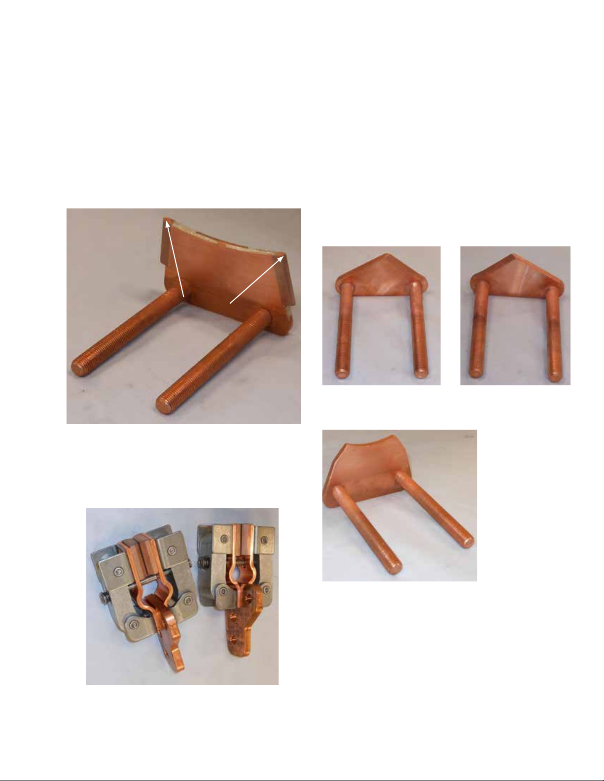
Reversing stationary contacts
Figure 4. Main stationary contact.
The main stationary contact is used for stationary tap
contacts and the neutral contact.
Main movable contacts
Figure 5. Main movable contact assembly.
Figure 6. VL reversing
stationary.
Figure 7. Figure 8. Neutral reversing
stationary.
The set of reversing switch stationary contacts on the QD5
tap-changer consist of three individual stationary contacts,
a VL-Reversing Stationary, a Reversing Neutral Stationary,
and a VR-Reversing Raise Stationary contact. The reversing
switch stationary contacts see less operating duty than the
main stationary contacts and therefore do not utilize the
copper-tungsten alloy arcing tips.
Figure 8. Figure 7. VR
reversing stationary.
3
Main reversing movable contacts
QD5 QUIK-DRIVE TAP-CHANGER INSTALLATION AND MAINTENANCE INSTRUCTIONS MN225012EN March 2016
Micro switches
Micro switches are use for the holding switch, reversing
logic, neutral indication and taping limit logic switches.
Two sets of normally closed switches are use to provide a
safety switch circuit to prevent the tap-changer from tapping
beyond 16R and 16L acting as a fail-safe to the mechanical
stop. The switches enable the tap changer to step back from
the mechanical stop when the holding switch is closed.
The micro switches used are rated for –40°C to 130°C,
5 Amp 125/250 Vac rating. The switches are designed to
exceed one million operations at QD5 tap-changer current.
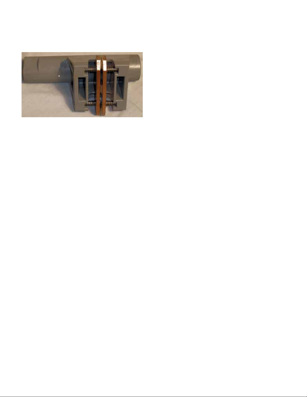
Figure 9. Reversing movable contact assembly.
The reversing switch changes the polarity of the tapped
winding. When the QD5 Quik-Drive tap-changer is in neutral
position, the reversing switch is located on the “VN”
Reversing Neutral Stationary Contact. In the open position
the reversing switch is not in the load current circuit.
The reversing switch motion on the QD5 tap-changer occurs
as the main movable contacts enter or leave the neutral
position. The QD5 tap-changer reversing switch movable
contacts interact with the three reversing stationary
contacts during the buck and boost operation of the tap
changer.
The first tap step in either direction rotates the Reversing
Segment actuator causing the Reversing Segment Actuator
arms to rotate the reversing switch and engage the
appropriate reversing stationary contact. When the tapchanger receives a signal for raise and the reversing switch
contact is in neutral, the reversing movable contacts will
move clockwise on to the VR stationary bridging the VR and
VN stationary contacts. In the lower direction from neutral
the reversing movable will move counter clockwise on to
the VL stationary contact. The reversing movable will be
bridging the VL and VN when moving in the lower direction.
QD5 tap-changer operating sequence
When the tap-changer is in the neutral position and the
control calls for a tap change, the following events occur:
1. Motor will start and drive the chain sprocket.
2. Rotation of the chain sprocket rotates the drive pinion.
3. The drive pinion cam engages and closes in the holding
switch.
4. Drive pinion roller engages the position indicator drive
gear advancing the position indicator pointer.
5. The sprocket drive roller engages the Geneva gear
rotating the Geneva gear.
6. As the sprocket rotates and the holding switch is
actuated, the sprocket cam dis-engages and releases
the brake.
7. The rotation of the Geneva gear causes the reversing
segment actuator to operate which moves the
reversing switch movable contacts, via the linkage tying
the reversing segment actuator to the reversing switch
from neutral to VR or VL.
8. Rotation of the Geneva gear relocates the movable
contacts on the stationary contacts.
9. Drive pinion cam returns to the open area opening the
holding switch.
10. Tap Change is completed.
4
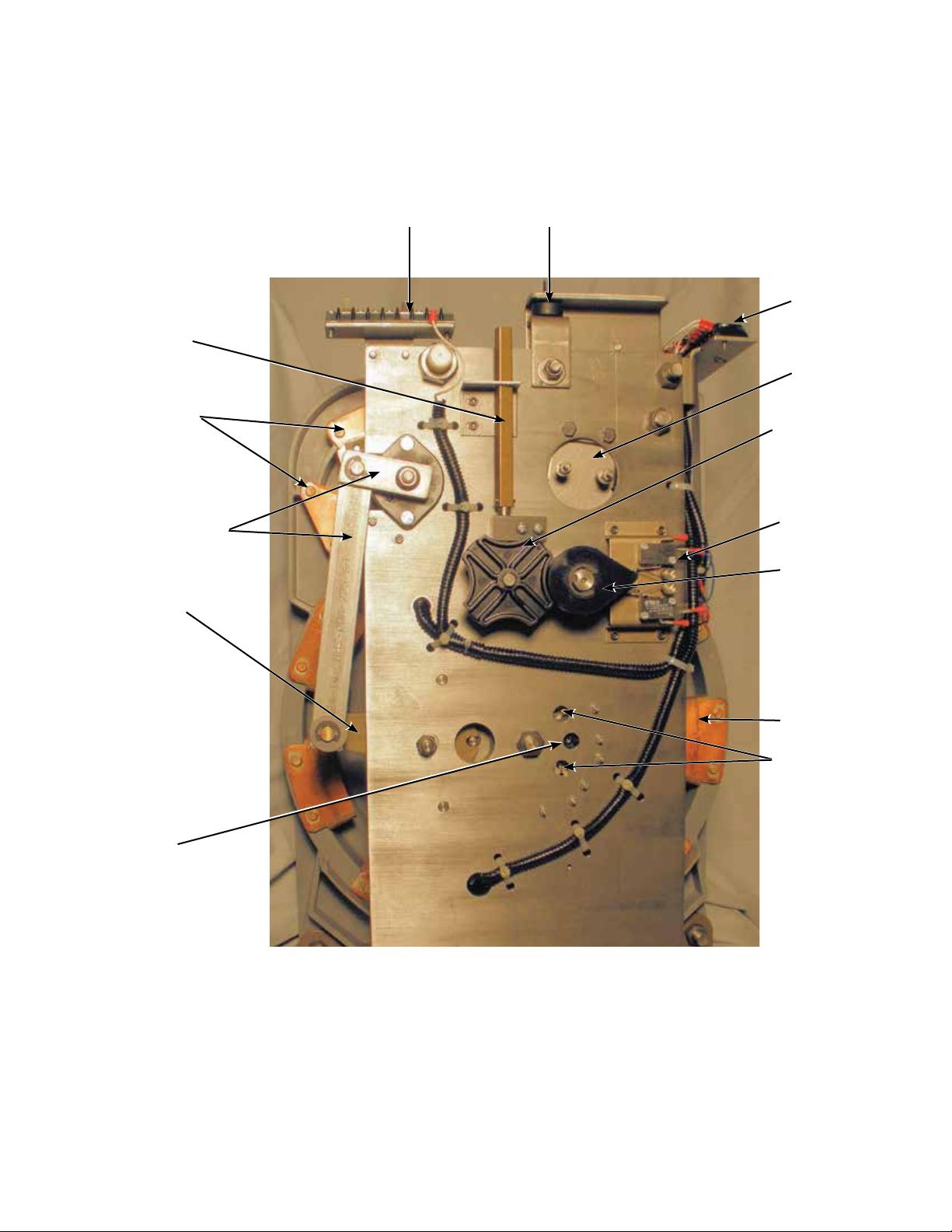
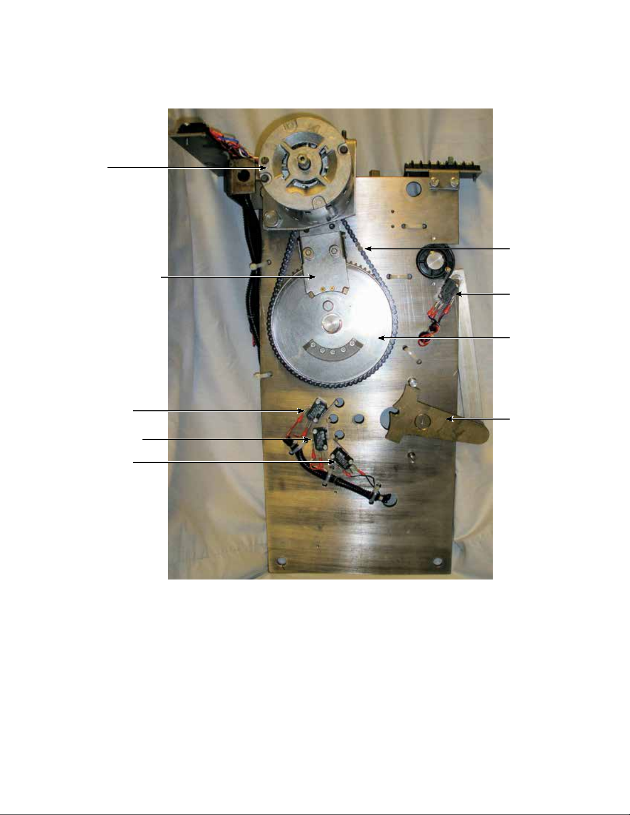
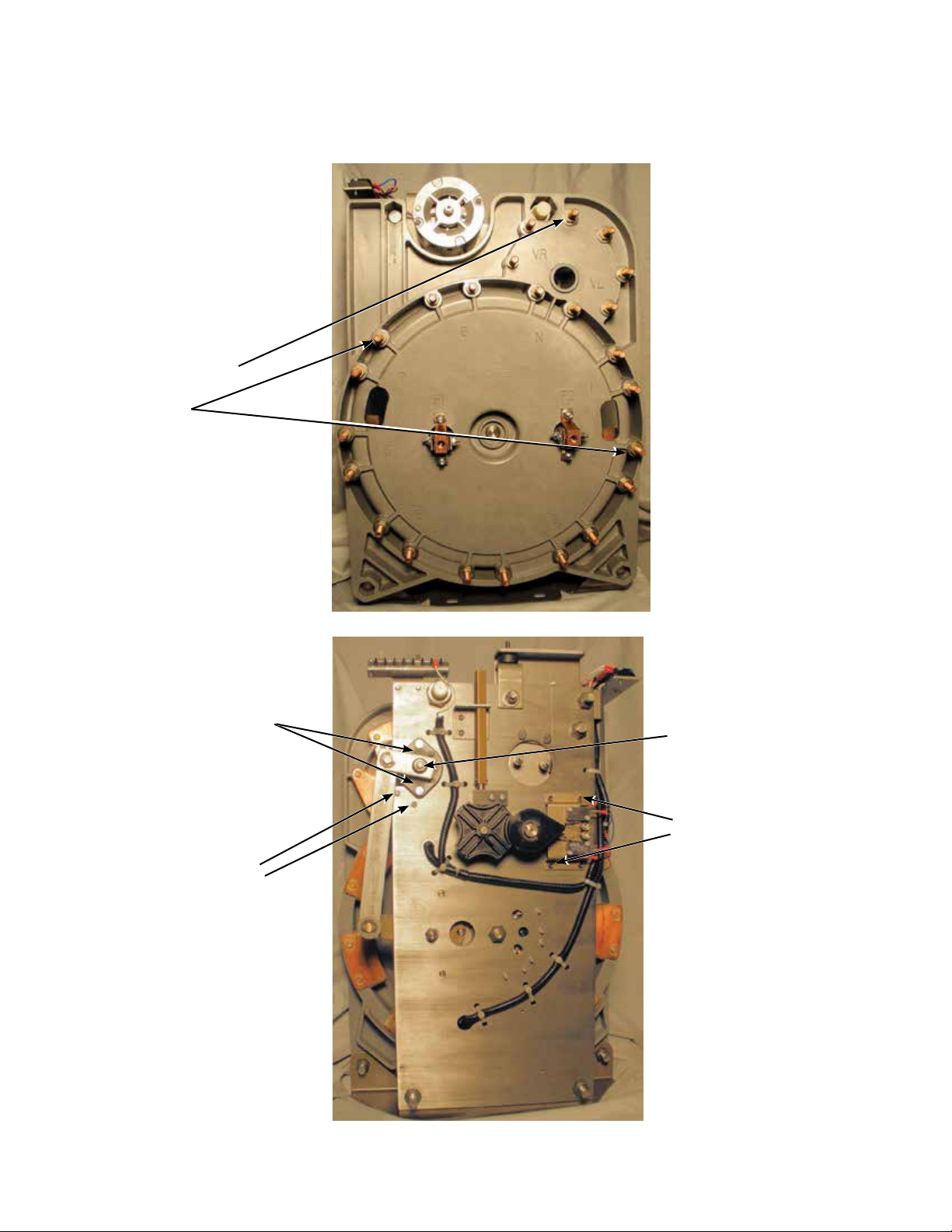
Maintenance, service and troubleshooting
QD5 QUIK-DRIVE TAP-CHANGER INSTALLATION AND MAINTENANCE INSTRUCTIONS MN225012EN March 2016
Position Indicator
Drive Tube
Reversing Stationary Contacts
Reversing Segment
Actuator Arms
Reversing
Actuator
Control Winding
Terminal Board
Motor/Chain
Tension Bumper
Main Terminal
Board
Brake Assembly
PI Drive Face
Geneva Gear
Holding Switch
Assembly
Drive Pinion Cam
Neutral
Switch
Figure 10. Tap-changer front view.
Main Stationary
Contact
Safety Switches
5
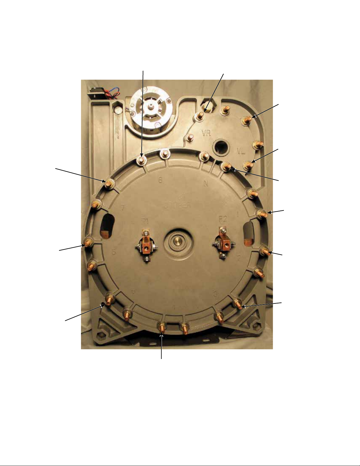
#7 Stationary
QD5 QUIK-DRIVE TAP-CHANGER INSTALLATION AND MAINTENANCE INSTRUCTIONS MN225012EN March 2016
#8 Stationary
VR-Reversing
Stationary
Contact
Reversing
Neutral
Stationary
Contact
VL-Reversing
Stationary
Contact
Neutral
Stationary
#1 Main
Stationary
Contact
#6 Stationary
#5 Stationary
Figure 11. Back side of QD5 tap-changer.
#2 Stationary
#3 Stationary
#4 Stationary
6
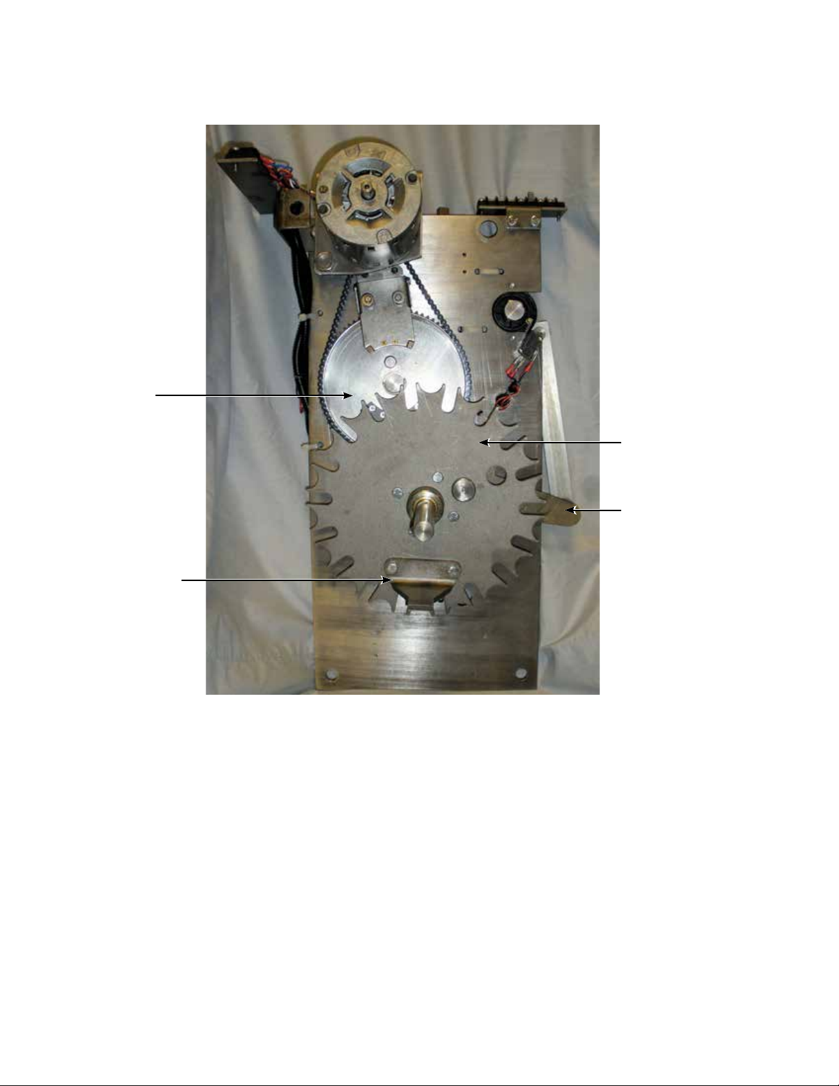
Motor
QD5 QUIK-DRIVE TAP-CHANGER INSTALLATION AND MAINTENANCE INSTRUCTIONS MN225012EN March 2016
Brake Assembly
Raise Safety
Switch
Neutral Switch
Lower Safety
Switch
Chain
Logic Switches
Drive Sprocket
Gear
Reversing
Segment
Actuator
Figure 12. Inside drive frame.
7
Drive Sprocket
QD5 QUIK-DRIVE TAP-CHANGER INSTALLATION AND MAINTENANCE INSTRUCTIONS MN225012EN March 2016
Gear
Movable Contact
Actuator Finger
Figure 13. Drive frame with Geneva gear.
Geneva Gear
Reversing Segment
Actuator
8

Reversing Neutral
QD5 QUIK-DRIVE TAP-CHANGER INSTALLATION AND MAINTENANCE INSTRUCTIONS MN225012EN March 2016
Stationary
VR Stationary Contact
Reversing Movable
Contact
VL Stationary
Contact
Main Movable
Contacts
Main Stationary
Contact #1
Movable Contact
Insulator Arm
Neutral Main
Stationary Contact
Main Stationary
Contact #8
Inner Collector Ring
Outer Collector Ring
Figure 14. Inside contact assembly.
9
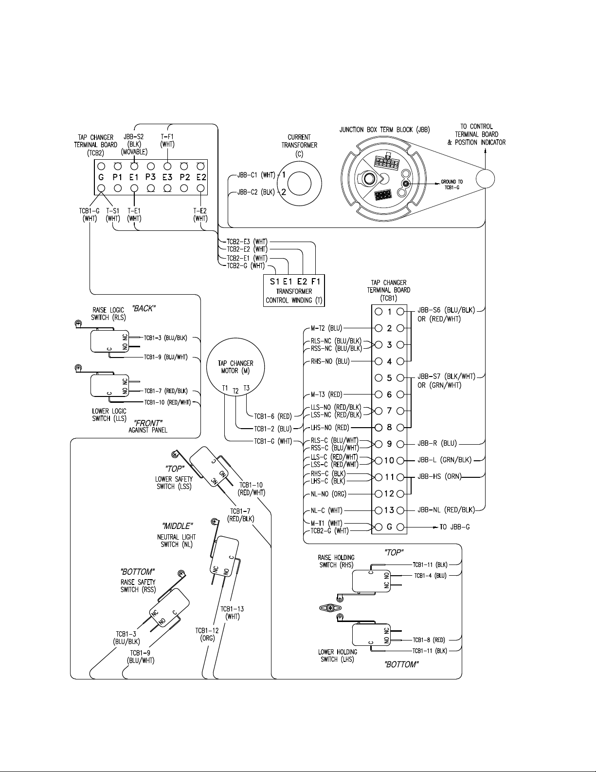
QD5 tap-changer schematic
QD5 QUIK-DRIVE TAP-CHANGER INSTALLATION AND MAINTENANCE INSTRUCTIONS MN225012EN March 2016
Figure 15. QD5 wiring schematic.
10
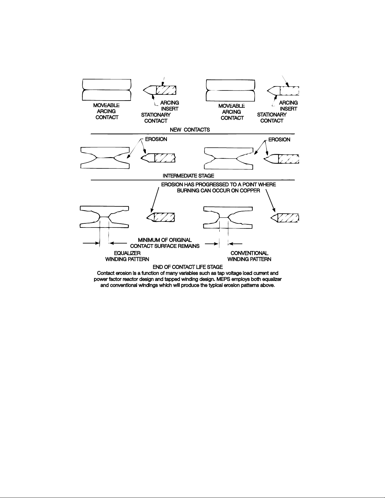
Contact erosion patterns
QD5 QUIK-DRIVE TAP-CHANGER INSTALLATION AND MAINTENANCE INSTRUCTIONS MN225012EN March 2016
Copper Copper
MOVEABLE
ARCING
CONTACT
EQUALIZER
WINDING PATTERN
Contact erosion is a function of many variables such as tap voltage load current and
power factor reactor design and tapped winding design. MEPS employs both equalizer
and conventional windings which will produce the typical erosion patterns above.
STATIONARY
MINIMUM OF ORIGINAL
CONTACT SURFACE REMAINS
ARCING
INSERT
CONTACT
NEW CONTACTS
NEW CONTACTS
EROSION
INTERMEDIATE STAGE
EROSION HAS PROGRESSED TO A POINT WHERE
BURNING CAN OCCUR ON COPPER
END OF CONTACT LIFE STAGE
MOVEABLE
ARCING
CONTACT
CONVENTIONAL
WINDING PATTERN
STATIONARY
CONTACT
EROSION
ARCING
INSERT
Figure 16. Contact life stages.
11
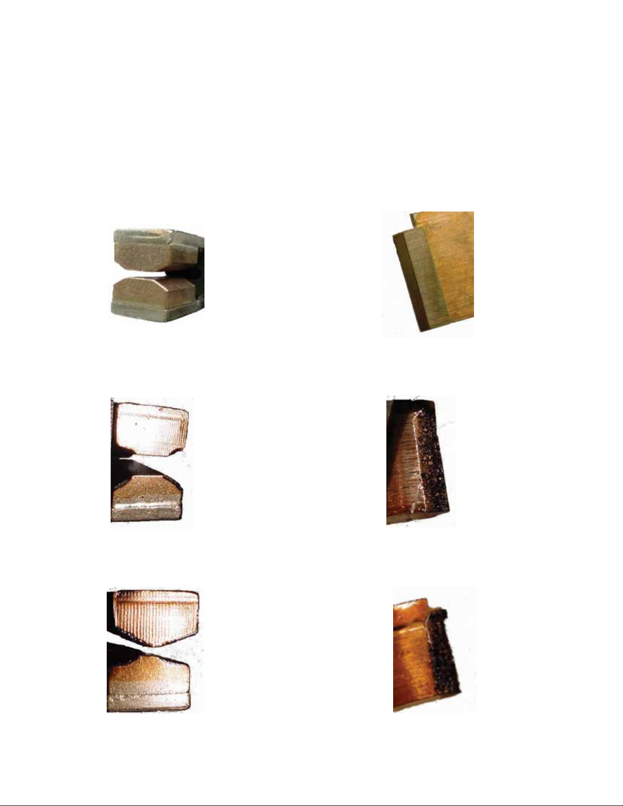
Contact inspection
QD5 QUIK-DRIVE TAP-CHANGER INSTALLATION AND MAINTENANCE INSTRUCTIONS MN225012EN March 2016
Tap-changer contacts are exposed to combination of
electrical, mechanical and thermal conditions that result
in deterioration. Erosion at the points subjected to arcing
duty is the most visible indication of wear. Figures 19 and
20 illustrate typical contact erosion patterns resulting from
normal service. Contacts at the end of life stage shown in
Figures 21 and 22 must definitely be replaced. The figures
below show actual contacts after various stages of contact
erosion.
New contacts
Figure 17. QD5 tap-changer movable contact. Figure 18. QD5 tap-changer stationary contact.
Intermediate life stage
Figure 19. QD5 tap-changer movable contact. Figure 20. QD5 tap-changer stationary contact.
End of contact life stage
Figure 21. QD5 tap-changer movable contact. Figure 22. QD5 tap-changer stationary contact edge.
12
QD5 tap-changer torque requirements
QD5 QUIK-DRIVE TAP-CHANGER INSTALLATION AND MAINTENANCE INSTRUCTIONS MN225012EN March 2016
Reversing
Stationary
Contact
Stationary
Contact
80–90 in-lbs
(9.0–10.2 Nm)
Figure 23. QD5 tap-changer stationary contact torque requirements.
30–40 in-lbs
(3.4–4.5 Nm)
4–5 in-lbs
(0.5–0.6 Nm)
180–192 in-lbs
(20.3–21.6 Nm)
12–18 in-lbs
(1.4–2.0 Nm)
Figure 24. Front drive torque requirements.
13
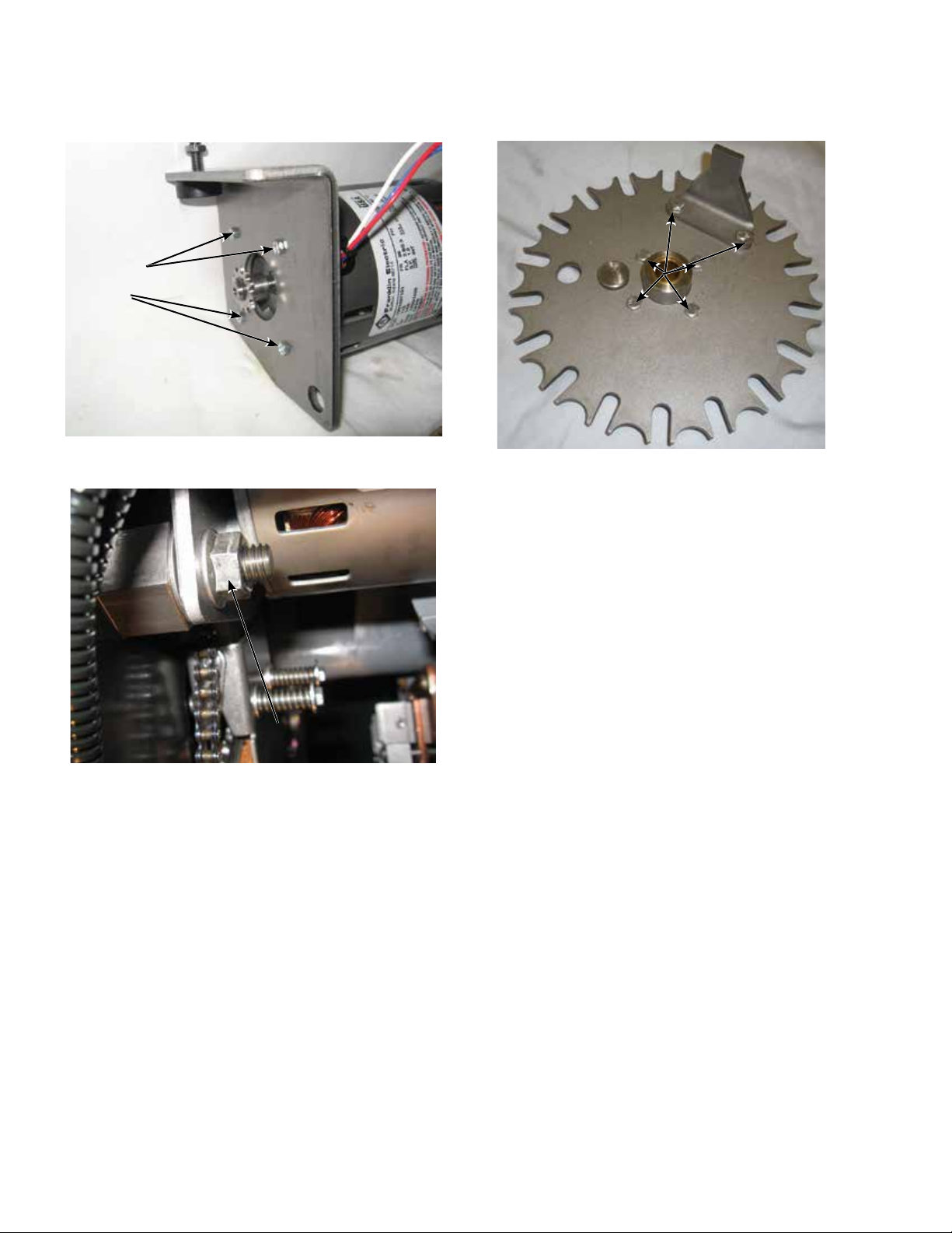
18–20 lb-in
QD5 QUIK-DRIVE TAP-CHANGER INSTALLATION AND MAINTENANCE INSTRUCTIONS MN225012EN March 2016
(5–2.2 Nm)
65–75 in-lbs
(7.5–8.5 Nm)
Figure 25. Motor to mounting bracket torque
requirements.
180–192 lb-in
(20.2–21.6 Nm)
Figure 26. Motor pivot stud and locknut torque
requirements.
Figure 27. Geneva gear torque requirements.
14
 Loading...