

Page 1
Power-Sure 700
Instruction manual
Effective September 2015
Supersedes September 2013
Page 2

Power-Sure 700
DISCLAIMER OF WARRANTIES AND LIMITATION OF LIABILITY
The information, recommendations, descriptions and safety notations in this document are based on Eaton Corporation’s
(“Eaton”) experience and judgment and may not cover all contingencies. If further information is required, an Eaton sales
office should be consulted. Sale of the product shown in this literature is subject to the terms and conditions outlined in
appropriate Eaton selling policies or other contractual agreement between Eaton and the purchaser.
THERE ARE NO UNDERSTANDINGS, AGREEMENTS, WARRANTIES, EXPRESSED OR IMPLIED, INCLUDING WARRANTIES
OF FITNESS FOR A PARTICULAR PURPOSE OR MERCHANTABILITY, OTHER THAN THOSE SPECIFICALLY SET OUT IN ANY
EXISTING CONTRACT BETWEEN THE PARTIES. ANY SUCH CONTRACT STATES THE ENTIRE OBLIGATION OF EATON. THE
CONTENTS OF THIS DOCUMENT SHALL NOT BECOME PART OF OR MODIFY ANY CONTRACT BETWEEN THE PARTIES.
In no event will Eaton be responsible to the purchaser or user in contract, in tort (including negligence), strict liability or
other-wise for any special, indirect, incidental or consequential damage or loss whatsoever, including but not limited to
damage or loss of use of equipment, plant or power system, cost of capital, loss of power, additional expenses in the
use of existing power facilities, or claims against the purchaser or user by its customers resulting from the use of
the information, recommendations and descriptions contained herein. The information contained in this manual is
subject to change without notice.
ii
Instruction manual IM1002004E September 2015 www.powerquality.eaton.com
Page 3

Contents
Power-Sure 700
General description ..........................1
Monitor ....................................1
Protection ..................................1
Operation ...................................2
Benefits of owning and using
the Power-Sure 700 ...........................2
Specifications ...............................2
Main transformer .............................3
Cabinet ....................................3
Input breaker ................................3
Industry standards ............................3
Theory of operation ...........................3
Sizing the Power-Sure 700 .....................4
Installation considerations ......................4
Inspection and installation ......................5
Unpacking ..................................5
Storing .....................................5
Choice of location ............................5
Inspection ..................................5
Installation procedure .........................5
Input wire size, grounding, and output wiring .......5
Startup sequence ............................7
Preventive maintenance .......................7
General troubleshooting guide ..................7
Troubleshooting ..............................7
Equipment required ...........................8
Power modules (SCRs) ........................8
Check the SCR snubber card ...................9
Check control card and filter card ................9
Final testing and adjustment ...................10
Control board measurements ..................22
Adjustment procedure ........................22
Parts kits ..................................22
Replacement parts ..........................22
Technical diagrams ..........................22
Cabinet dimensions ..........................36
Manual bypass switch ........................36
Normal mode ...............................36
Bypass mode ...............................36
Metering option .............................37
Warranty ..................................37
Instruction manual IM1002004E September 2015 www.powerquality.eaton.com
iii
Page 4

Power-Sure 700
iv
Instruction manual IM1002004E September 2015 www.powerquality.eaton.com
Page 5

General description
IMPORTANT
Save these instructions. Please read this manual before
using equipment.
General description
The Power-Sure™ 700 is a continuous duty electronic
voltage regulator designed to supply reliable, clean
regulated power to critical loads. An efficient design with
state-of-the-art microprocessor controlled solid-state devices
provide immunity to all line disturbances.
The basic design consists of a three-phase triple-shielded
isolation transformer with seven separate voltage taps per
phase. Output regulation is achieved by monitoring the
input and automatically switching taps anytime the input
line sags or surges. The special process of triple-shielded
isolation transformers provide superior common mode and
transverse mode noise attenuation. Automatic switching
occurs during current zero, allowing noise-free switches
for both leading and lagging power factor loads that are
connected to the Power-Sure 700.
Monitor
Monitoring of the Power-Sure 700 is simple, clean, and
effective. Three green light indicators are utilized to
display“POWER ON” (output line to neutral for each
phase) and one red light indicator to display “ALERT.” The
“POWERON” display is connected directly to the output
that indicates the Power-Sure 700 is operating properly
with just a quick glance. The “ALERT” display represents
an overtemp problem when illuminated, and will shut down
the output, but cooling fans remain on. Overtemp thermal
sensors are strategically located at critical points on the
regulator assemblies and transformer. The main AC input
circuit breaker must be turned off in order to reset the
“ALERT” light.
Protection
Protection is accomplished very effectively to minimize
failures and the cost of repairs. A total of four major devices
protect the Power-Sure 700.
1. The input is protected with an integrally mounted
AC circuit breaker for abnormal current overloads
and provides a convenient means of disconnecting
utility power.
2. The electronic regulating devices are protected
with fast-acting semi-conductor fuses. These fuses
are designed to clear before damage occurs to the
more expensive SCR regulating devices. The main
transformer is protected by fuse links connecting the
SCR regulators together, and are designed to clear in
the event that two or more SCRs should fail. This will
prevent a transformer tap short and the possibility of
transformer failure.
3. Overtemp sensing devices are mounted at critical
points on the SCR regulating assembly and the main
transformer. When an overtemp condition exists,
the “ALERT” light will illuminate and hold until the
overtemp is corrected. There are no automatic shutoff
circuits for the “ALERT” condition. The main AC input
breaker must be turned off in order to reset the
“ALERT” light.
4. Optional dedicated surge protective device can be
installed internally if requested at time of order. This
surge suppression device (SPD) is a CVX 50 kA SPD
forPower-Sure 700 units 50 kVA and below, and
CVX100 kA SPD for Power-Sure 700 units 75 kVA
andabove. This unit provides effective transient voltage
surge suppression and will help to prolong the life of
the Power-Sure 700.
Instruction manual IM1002004E September 2015 www.powerquality.eaton.com
1
Page 6
Operation
Operation
The Power-Sure 700 is operated by simply turning on the
main AC input circuit breaker. All units 50 kVA and larger are
equipped with a bypass switch as a standard feature. For
units 45 kVA and smaller, the bypass switch is optional. This
is a no load switch and MUST only be operated when the
unit is OFF. The bypass switch should be in the “NORMAL”
position unless a problem occurs with the system. If a
problem occurs, turn OFF the main AC circuit breaker
and turn the bypass switch to the “BYPASS” position.
Re-energize the system by turning on the AC circuit breaker
and contact the Customer Support Department for repairs.
Any “ALERT” condition requires the main AC input breaker
to be turned off in order to reset the “ALERT” light.
FOR ASSISTANCE, CALL 1-800-809-2772, option 4, and
then option 2.
Bene ts of owning and using the
Power-Sure 700
Line harmonic filtering
Small physical size
Simple and inexpensive installation
Highly efficient
Quiet operation
Low BTU output
Low failure rate
Seven-tap, microprocessor control and diagnostics
UL® Listed to 1012 standards
Priced to be affordable
Conservatively rated
Extremely high surge capability
Simple operation
Input electronic circuit breakers
Nationwide customer support service
Load regulation: output maintained within 3% from no
load to full load
Response time: <1/2 cycle
Correction time: output will correct to within ±3% of
nominal in 1.5 cycles or less
Harmonic distortion: Less than 1.0% THD added to
the output waveform under any dynamic linear loading
conditions presented to the line regulator
Transverse-mode noise attenuation: 3 dB down at 1000 Hz,
40 dB/decade to below 50 dB with resistive load
Common-mode noise attenuation: 146 dB
Audible noise: 45 dB or less
Turn on characteristics: when energized, voltage
overshoot will be less than 5% of nominal for 1 cycle
or less
Overload rating: 1000% for 1 cycle and 200% for
10 seconds
Ambient rating: –10º to +40º Celsius
Integral manual rotary maintenance bypass switch
standard on 50 to 500 kVA units and optional on
smaller units
ote: N 50 Hz models available.
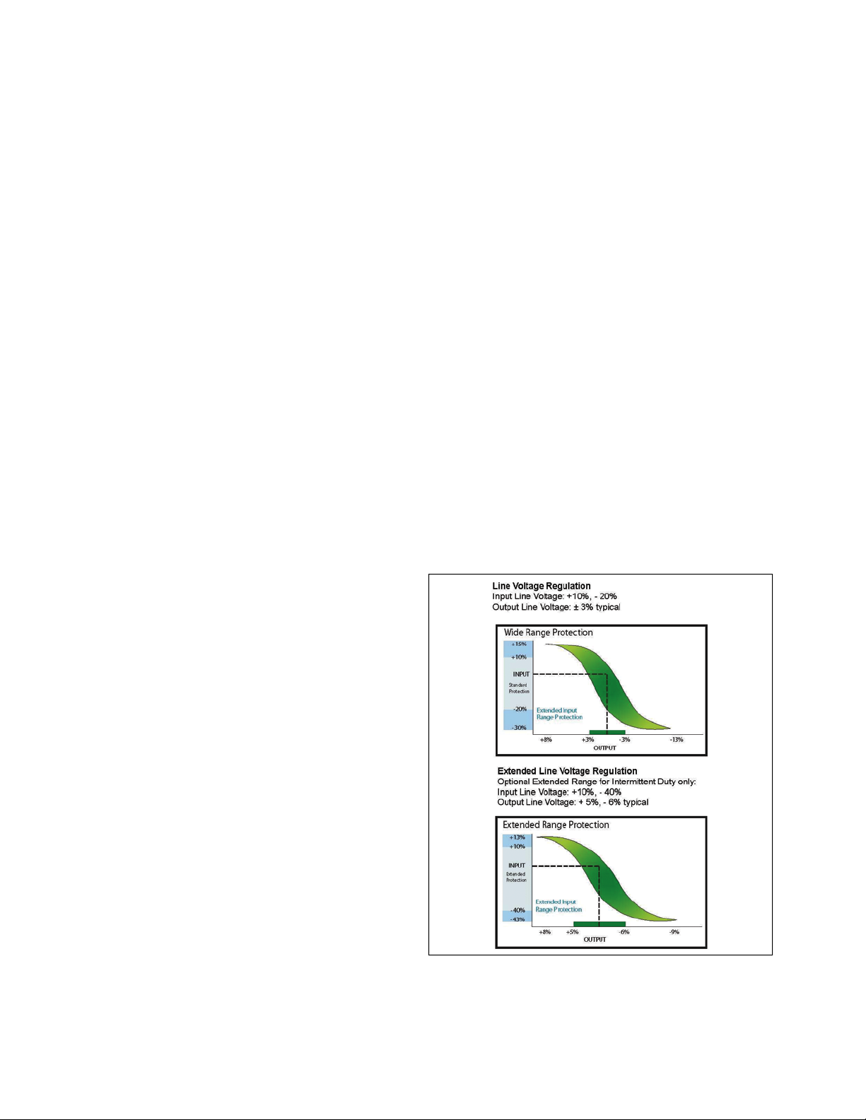
Figure 1. Regulation graphs
Speci cations
Dynamic electrical specifications
Output: maintained to within ±3% of nominal
Input: +10% to –23% of the nominal rated input
Frequency: 60 Hz ±3 Hz
Input power factor: >0.99 PF with resistive load
Line regulation: output is ±3% of nominal for input
variations of +10% to –23% of nominal
2
Instruction manual IM1002004E September 2015 www.powerquality.eaton.com
a
a
ab
a
Optional extended input regulation range provided on some units.
If provided, reference the description next to the units specification tag.
b
Between 160 V and 229 V at 208 V nominal. Between 369 V and 528 V
at 480 V nominal.
Page 7

Main transformer
Main transformer
Windings: all copper
Magnetics: grain orientated, M6 grade, stress-relieved
transformer steel is utilized for minimum losses and
maximum efficiency
Insulation: Class (N) 200 all sizes
Shielding: multiple triple copper shield to minimize
interwinding capacitance, transient, and noise coupling
between primary and secondary windings
Cooling: convection, operating temp is 130 degrees
Celsius maximum rise above ambient
Isolation: output is fully isolated from input
Cabinet
Heavy-gauge industrial steel throughout. Metal is
anti-corrosive phosphate treated prior to paint. Paint
is a baked finish.
Input breaker
Main input molded-case circuit breaker, rated at 125% of full
load input current.
Industry standards
Listed to UL 1012, standard for “power units other than
Class 2.”
Theory of operation
The Power-Sure 700 provides the triple function of isolation,
noise attenuation and voltage regulation. The first two
functions are provided by the power transformer, where as
the third function of voltage regulation is achieved through
solid-state thyristors (SCRs) connected to taps on the power
transformer. A microprocessor monitors and controls the
overall function of regulating the system.
The power transformer is manufactured with a unique
method of shielding which produces very low capacitive
coupling between the primary and secondary. This low
coupling provides excellent attenuation of the commonmode noise. In addition, special care is taken in the design
of the transformer to attenuate transverse-mode noise
above 1000 Hz.
The power transformer has taps to which solid-state
switches (SCRs) are connected.
The voltage regulator incorporated in the Power-Sure 700
is microprocessor controlled to achieve optimum correction
time of input voltage sags and surges. The response time is
typically one half (1/2) cycle for 100% correction, therefore,
a very smooth switch takes place undetected by computer
equipment.
As the input voltage (building power) varies, the voltage
available at each tap of the transformer will also change.
The amount of variation is dependent upon the input sag
or surge, turns ratio, and transformer losses.
By selecting a particular tap voltage, the output can be kept
within a tight range. The way in which this is accomplished
is that an electronic control card using a microprocessor
continually monitors the input voltage. When a voltage
fluctuation occurs, which exceeds the limit of rated regulation
(typically ±3%), the output is switched to another tap, that
is within the required range. This “switch” will be made at
the next current zero crossing to allow for both leading and
lagging power loads to be connected to the conditioner.
Instruction manual IM1002004E September 2015 www.powerquality.eaton.com
3
Page 8
Sizing the Power-Sure 700
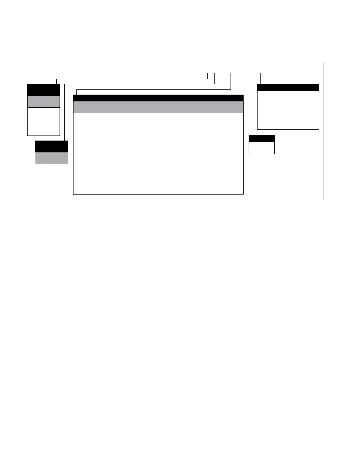
Table 1. Eaton Power-Sure 700 ordering guidelines
Nominal
input voltage
Delta input:
L, L, L, G
B = 208
C = 240
H = 400
D = 480
E = 600
Nominal
output voltage
Wye output:
L, L, L, N, G
L = 120/208
M = 230/400
N = 277/480
P = 347/600
kVA
010
010
015
015
025
030
045
050
075
100
125
150
225
300
500
Weight
(lbs)
440
520
520
600
870
890
950
1,176
1,575
2,014
2,137
2,240
3,300
4,000
5,500
BTUs/ hr
1,025
1,205
1,540
1,540
2,560
3,090
4,600
7,332
9,514
11,833
14,748
17,698
23,000
30,750
51,250
kVA ratings and dimensions
Bypass Metering
Optional
Optional
Optional
Optional
Optional
Optional
Optional
Yes
Yes
Yes
Yes
Yes
Yes
Yes
Yes
No
Yes
No
Yes
Yes
Yes
Yes
Yes
Yes
Yes
Yes
Yes
Yes
Yes
Yes
T - k -
Cabinet size
Dimensions H x W x D in inches (mm)
30.20 x 22.20 x 29.00 (767.1 x 563.9 x 736.6)
44.20 x 22.20 x 29.00 (1122.7 x 563.9 x 736.6)
30.20 x 22.20 x 29.00 (767.1 x 563.9 x 736.6)
44.20 x 22.20 x 29.00 (1122.7 x 563.9 x 736.6)
44.20 x 22.20 x 29.00 (1122.7 x 563.9 x 736.6)
44.20 x 22.20 x 29.00 (1122.7 x 563.9 x 736.6)
44.30 x 45.90 x 29.00 (1125.2 x 1165.9 x 736.6)
66.00 x 29.00 x 35.50 (1676.4 x 736.6 x 901.7)
76.00 x 34.40 x 35.50 (1930.4 x 873.8 x 901.7)
76.00 x 34.40 x 35.50 (1930.4 x 873.8 x 901.7)
76.00 x 34.40 x 35.50 (1930.4 x 873.8 x 901.7)
76.00 x 34.40 x 35.50 (1930.4 x 873.8 x 901.7)
77.40 x 56.00 x 41.50 (1966.0 x 1422.4 x 1054.1)
77.40 x 56.00 x 41.50 (1966.0 x 1422.4 x 1054.1)
77.00 x 72.40 x 48.40 (1955.8 x 1839.0 x 1229.4)
Options
Blank = No options
B = Bypass switch
M1 = Standard metering
(IQ 130)
M2 = Premium metering
(IQ 150)
S = Surge
Frequency
6 = 60 Hz
5 = 50 Hz
A
2
A
Units with no surge protection option, bypass option or metering will have blanks in the last three spaces in the catalog number.
B
Bypass is standard on 50 kVA and larger units and an option on 45 kVA and smaller units.
otes:N Listings—UL Listed, CSA Certified, except for 600 V: no UL, CSAon 600 V units.
For output distribution, call factory. K factor rated units availableon request.
Sizing the Power-Sure 700
When sizing the Power-Sure 700, be sure to take into
consideration all loads and circuits the unit is to supply.
A good way to ensure that the Power-Sure 700 is sized
properly is to use the following guidelines:
List each piece of equipment, include model, voltage,
current, and kVA
Calculate kVA of load plus a safety margin
When this is not possible, gather the data by reading
the specification plate of the equipment you plan on
backing up
One method is to ask the vendor of the equipment to
supply you with the information you need
Be sure to verify the input supply voltage and the output
requirements of the Power-Sure 700
Installation considerations
Prior to installing the Power-Sure 700, be sure to take into
consideration the site you have selected. Power Conditioners
produce heat and therefore require ventilation, as well as
accessibility.
Consider these factors:
Ventilation
Size of the Power-Sure 700
Weight load
Audible noise requirements
Monitors
Options
Clean environment
Proper ground techniques
Input source voltage
Receiving facilities
Distribution of power
Room temperature
Clearances
Accessibility
Excessively long power runs
4
Instruction manual IM1002004E September 2015 www.powerquality.eaton.com
Page 9

Inspection and installation
Inspection and installation
WARNING
There are dangerously high voltages present within
the enclosure of the power supply system. Under no
circumstances should any person reach within the
enclosure of this equipment. All service to this piece
of equipment should be performed by qualified
personnel only.
Unpacking
Upon receipt of the unit, visually inspect for shipping
damage. If any damage is found, the Purchaser must
contact the Carrier immediately and file a shipping
damage claim.
ote:N Be sure to remove top and side panels and inspect
inside unit for shipping damage.
Eaton should be notified if the nature of damage is such
that operation of the equipment has been impaired. Please
call 1-800-809-2772, option 4, and then option 2.
Storing
If it is necessary to store the unit for a period of time
before it is installed, be sure to place the unit in a clean,
dry area. To prevent excessive dust from accumulating on
the unit, it is advisable to protect it by replacing it in the
original container. The unit must be handled at all times with
the same care you would give to any piece of precision
industrial equipment.
Choice of location
The unit has been completely inspected and extensively
tested under various load conditions prior to shipment.
Care to install it at a proper location will ensure long
trouble-free operation.
The unit is air cooled with the air intake at the bottom
and exhausts at the top, front or at the sides. Therefore,
it should be installed in a clean, dry place with enough
clearance to allow a free flow of air. Allow at least
4.00 inches (101.6 mm) of space between the unit and
the wall or other equipment. Allow enough space for
maintenance on all four sides of larger units.
Inspection
A. Remove top and side panels (not applicable on 225 kVA
and larger).
B. Check all electrical connections to be sure none have
loosened during shipment. Tighten if necessary. Check
for any internal damage.
C. Check the spec. plate on the front of the unit to be
sure that the voltage and frequency match the available
power supply. Under no circumstances should the
unit be connected to a power source which does not
conform to the spec. plate rating.
Installation procedure
A. Verify that the input voltage to the unit matches the
unit’s specification plate.
B. Refer to installation diagrams on page 27–page 35
for input and output connection recommendations and
conduit locations.
Input wire size, grounding, and output wiring
A. Conduit should be used for both input and
output wiring.
B. Minimum ground wire size is based on 2011 National
Electrical Code® Table 250.122.
®
C. Input wire size is based on 2011 NEC
specifying not more than three conductors in a raceway
based on ambient of 30 degrees Celsius, and wire rated
at 75 degrees Celsius.
D. Output neutral to ground is already bonded during
manufacturing of the Power-Sure 700.
E. Output requires four (five including ground wire)
conductors in a raceway assuming neutral as a
current carrying conductor. This requires conductors
to be derated by using a multiplier of .8, reference
2011 NEC Article 310.15(B)(3)(a).
Example
1. Assume #10 wire maximum current = 25 A.
2. Multiply 25 x .8 = 20.
3. 20 A is maximum current for #10 wire in a raceway
with four conductors.
ote:N Installation is subject to local codes—verify with a
local electrical inspector.
Table 310.15(B)(16)
Instruction manual IM1002004E September 2015 www.powerquality.eaton.com
5
Page 10

Input wire size, grounding, and output wiring
Table 3. Wire size chart
Unit size
in kVA
Input breaker
size (amperes)
Input
wire size
Minimum ground
wire size
208 Vac input
10 40 #8 #10
15 60 #6 #10
25 110 #2 #6
30 110 #2 #6
45 175 2/0 #6
50 175 3/0 #6
75 300 #350 #4
100 400 3/0
a
125 500 250 kcmil
150 600 350 kcmil
225 800 500 kcmil
300 1200 500 kcmil
500 2000 500 kcmil
a
a
a
b
d
#3
#2
#1
1/0
3/0
250 kcmil
240 Vac input
10 30 #10 #10
15 50 #8 #10
25 100 #3 #8
30 100 #3 #8
45 150 1/0 #6
50 150 2/0 #6
75 250 #250 #4
100 350 500 #3
125 400 3/0
a
150 500 250 kcmil
225 800 500 kcmil
300 1000 500 kcmil
500 1600 500 kcmil
a
2 pcs.
b
3 pcs.
c
4 pcs.
d
5 pcs.
a
a
b
c
#3
#2
1/0
2/0
4/0
Unit size
in kVA
Input breaker
size (amperes)
Input
wire size
Minimum ground
wire size
480 Vac input
10 15 #10 #14
15 25 #10 #10
25 50 #6 #10
30 50 #6 #10
45 80 #4 #8
50 80 #4 #8
75 125 #1 #6
100 175 2/0 #6
125 200 3/0 #6
150 250 250 kcmil #4
225 350 500 kcmil #3
300 500 250 kcmil
500 800 500 kcmil
a
a
#2
1/0
600 Vac input
10 15 #10 #14
15 20 #10 #12
25 40 #8 #10
30 40 #8 #10
45 60 #6 #10
50 70 #4 #8
75 100 #3 #8
100 150 1/0 #6
125 175 2/0 #6
150 200 3/0 #6
225 300 350 kcmil #4
300 400 500 kcmil #3
500 700 400 kcmil
a
1/0
ote:N Refer to NEC for output wire size based on
output breaker size as mentioned in Step E
on the previous page.
6
Instruction manual IM1002004E September 2015 www.powerquality.eaton.com
Page 11
Startup sequence
Startup sequence
WARNING
There are dangerously high voltages present within
the enclosure of the power supply system. Caution
must be taken when working with the enclosure. It is
recommended that all work be performed by qualified
electrical personnel only.
ote:N Initial startup should be performed with no-load
on system.
1. Re-install all panels that may have been removed
during installation.
2. Make sure the input circuit breaker is in the OFF position.
3. Energize the primary building power.
4. Turn on the main AC input breaker.
5. Verify that the output voltage is within the
specified range.
6. Verify output phase rotation is correct.
7. Turn the system off.
8. Connect the loads one at a time and repeat Step 5.
General troubleshooting guide
Table 4. General Troubleshooting Guide
Symptom Probable causes
1. No output on one or
more phases
2. Output is too high or too low A. Control card adjustment
3. Input breaker tripping off A. Defective breaker
4. Blowing semi-conductor fuses A. Shorted SCRs or power modules
5. No output voltage A. Defective over/under output
A. Blown fuse
B. Defective SCR or power module
C. Defective control card
D. Defective sense card
E. No input
B. Defective control card
C. Defective sense card
D. Defective SCR or power module
E. Input out of range
B. System overloaded
C. Over/undervoltage detection is shutting
down system (see symptom #2)
D. Defective over/under detection card
E. Shorted taps
B. Output loads shorted
detection PCB
Preventive maintenance
WARNING
Danger of electrical shock. Turn off all power supplying
this equipment prior to maintenance.
To ensure longer component life and trouble-free operation,
minor preventive maintenance procedures should be
performed at regular intervals, for example once every
year. More frequent inspection intervals would be needed
for more severe operating conditions and larger number of
hours of continuous operation.
A. Remove top and side panels and at each service
inspection any accumulated dust, dirt or foreign particles
should be carefully removed. Special care should be
exercised in cleaning the thyristors, heat sinks, and the
control assembly.
B. Inverse parallel silicon rectifiers (SCRs) or thyristors:
The silicon controlled rectifiers (SCRs) usually fail in the
shorted mode. When this happens, normally the fusible
link in series with the SCR will be blown open to clear
the short and prevent damage to the transformers. The
individual SCR can be checked with an ohmmeter. Refer
to page 8 for resistance checking procedures.
C. Replace top and side panels. Turn unit on with no load.
D. Turn on loads.
E. Check to verify all fans are operational.
ote:N Preventive maintenance plans are included on
page 38 of the manual.
WARNING
There are dangerously high voltages present within
the enclosure of the power supply system. Under no
circumstances should any person reach within the
enclosure of this equipment. All service to this piece
of equipment should be performed by qualified
personnel only.
Troubleshooting
ote:N Circuit diagrams in this manual are for reference only.
Always refer to the actual circuit diagrams received
with the system.
Introduction
This procedure is written in a specific order and must be
used from start to finish when troubleshooting. Any steps
skipped over may cause serious damage to the system.
Instruction manual IM1002004E September 2015 www.powerquality.eaton.com
7
Page 12
Equipment required
Equipment required
True rms digital multimeter, SCR tester, common hand tools.
Step 1: Disassembling the power line conditioner
A. Turn off the power to the conditioner at its source.
B. Turn off the input circuit breaker on the unit and the
output circuit breakers to all loads (remove all loads
from unit).
C. Remove the top and side covers to the conditioner.
Step 2: Electrical connections, fuses
Refer to diagrams on page 11–page 16 for component
locations.
A. Inspect the unit for proper tightness of all electrical
connections, burnt, frayed, broken, or loose connections
and components in these areas.
Input and output connections, SCR assembly, SCR
snubber, output filter assembly, MOVs (metal oxide
varistors), circuit boards, bypass switch, and
transformer connections.
B. Correct and tighten any loose connections, replace
any physically burned or broken components.
C. Check all fuses in system.
ote:N Remove fuses from circuit when checking to avoid
false readings.
D. Time delay fuses, semi-conductor fuses, fan fuses,
circuit board fuses, SCR fusible Link wire.
Power modules (SCRs)
Refer to diagram on page 17 for 10–30 kVA SCR
assembly, page 18 for 45–150 kVA SCR assembly,
page 19 for 225–300 kVA SCR assembly, and page 20
for 500 kVA SCR assembly.
1. Unplug the connections to the control cards
Part # 49120/407415 labeled TB1, TB2, and TB3.
2. Disconnect any cooling fans in the unit so your SCR
resistance checks are not interfered by fan motor coils.
Also, remove main semi-conductor fuse located on
all three SCR assemblies and any wires attached to
the fuse. Each power module contains two inverse
parallel SCRs.
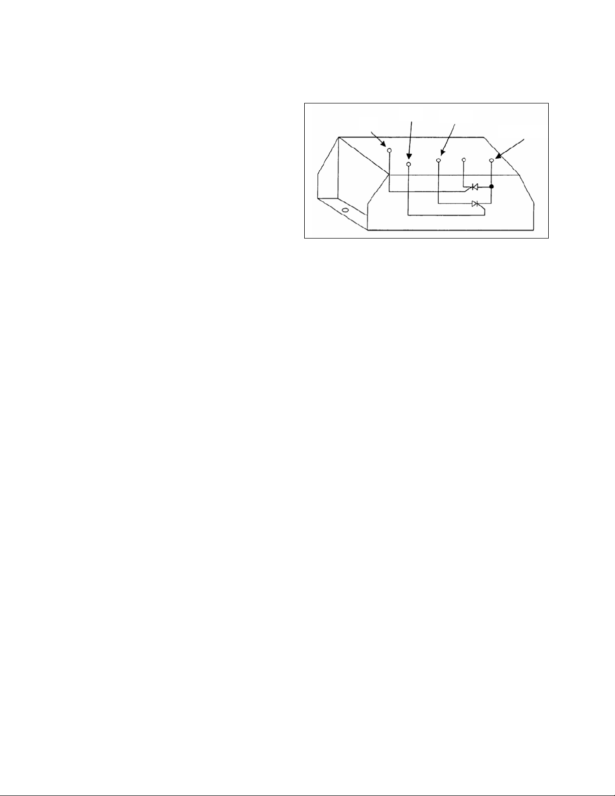
Figure 2. Power module
G2
G1
Shunt
Transformer
3. Measure the following resistance on each power
module. There are seven per phase or 21 for all three
phases. Refer to the circuit diagrams received with
your unit.
ote:N When checking the power module assembly, if more
than one defective power module is present it will
appear as if all the power modules are defective. If
this is the case, the individual power module must be
isolated from the power transformer.
a. K1-1 to K2-1 through K1-7 to K2-7 = High resistance,
1 megohm.
b. K1-1 to G1-1 through K1-7 to G1-7 = 10 to 90 ohms.
c. K1-1 to G2-1 through K1-7 to G2-7 = 1 megohm.
d. K2-1 to G2-2 through K2-7 to G2-7 = 10 to 90 ohms.
e. K2-1 to G1-1 through K2-7 to G1-7 = 1 megohm.
f. G1-1 to G2-1 through G1-7 to G2-7 = 1 megohm.
4. Replace any defective power modules. This may require
removing the shunt and loosening the K1 bus from all
the power modules to get the defective power module
out. Use only equivalent hardware and heat sink grease
when replacing power modules.
5. If a resistance measure is questionable, a more
thorough test will ensure an SCR is good or bad by
using the following test procedure.
a. Completely isolate SCR under test by removing all
connections to the device.
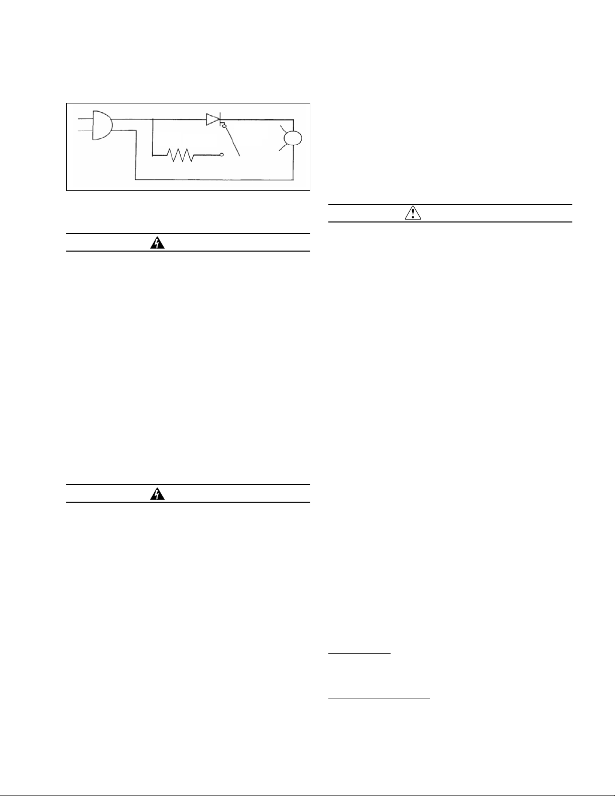
b. Hook up the following test circuit to each individual SCR.
c. Plug in SCR tester. With switch #1 open light bulb
should be off. If not, replace SCR.
d. Close switch #1. Light bulb should illuminate to about
3/4 brilliance. If not, replace SCR. See Figure 3.
8
Instruction manual IM1002004E September 2015 www.powerquality.eaton.com
Page 13
Check the SCR snubber card
Figure 3. SCR tester
1K Ω 1 Watt
6. Re-assemble the power module assembly, make sure
all connections are tight.
Swi tch 1
WARNING
Do not connect the semi-conductor fuse, wires or fan
wires at this point.
Check the SCR snubber card
1. Three components make up the SCR snubber—
resistors, MOVs, and capacitors. Check for open
resistors. Check MOVs for shorts, they should read
high resistance when ohmmeter is placed across them.
Resistance check each capacitor. The DC resistance
across the snubber capacitor-should look capacitivethat is high resistance after the meter charges the
capacitor. If it measures open or shorted, replace the
snubber card.
2. RE-CONNECT SEMI-CONDUCTOR FUSE, ALL
WIRES, AND FANS. DOUBLE CHECK THAT ALL
CONNECTIONS ARE SECURE.
ote:N Control board # 49120 is for 10 kVA to 50 kVA units.
Control board # 407415 is for 75 kVA and larger.
WARNING
Do not connect TB1, TB2, and TB3 connectors from the
control cards #49120/407415 yet.
Check control card and lter card
1. Verify input to the conditioner matches the unit’s
specification. Also verify correct control board
#49120/407415 jumper setup on page 21.
2. Disable the over/undervoltage shutdown card #35867
(optional card) by removing connectors K1 and K2 on
the card.
3. Turn on AC input breaker to unit.
IMPORTANT
Extreme caution must be taken when measuring voltages
on Molex connectors. Do not press meter leads into
connectors or bend connectors back.
4. Measure the following voltages on wires feeding
the TB1 Molex connector to the control card on all
three phases.
Pins 1 and 3 = 4–6 Vac.
ote:N When the connector is plugged in, this voltage is
around 3 Vac.
Pins 7 and 8 = 120 Vac
If this voltage is incorrect or not present, then check
the fuses associated with the filter card or replace filter
card and re-check voltages.
5. Turn main AC circuit breaker off. Plug in connectors TB1
and TB3 only. On the control card #49120 / 407415 on
all three phases.
6. Turn main AC on. With DC voltmeter on the millivolt
scale, check between TP1 and TP GND of the control
card and adjust pot P2 so meter reads “0” millivolts or
close as possible.
ote:N This step does not apply to control board # 407415.
ote:N Refer to page 21 for test points and pot locations
on control card.
7. Use the following formula to calculate the next
adjustments. You must calculate each input phase for
each control card or a total of three calculations.
a. For phase 1 control card, measure AC input at Line 1
to Line 2.
b. For phase 2 control card, measure AC input at Line 2
to Line 3.
c. For phase 3 control card, measure AC input at Line 1
to Line 3.
Formula
AC Input x 2.47 = Volts DC at TP2
480 (Nominal)
Example
475 Volts AC Input x 2.47 = 2.44 Volts DC at TP2
480 (Nominal)
Instruction manual IM1002004E September 2015 www.powerquality.eaton.com
9
Page 14

Final testing and adjustment
8. After calculations are complete, place DC voltmeter
on the 20 V scale and check between TP2 and TP GND
on control card. Adjust pot P1 so meter reads DC level
calculated in Step 7 for all three phases.
ote:N If adjustments in Steps 6 and 7 are not possible,
replace control card # 49120/407415 and repeat Steps
6 and 8.
ote:N Be sure to turn power off when replacing circuit
boards.
ote:N Be sure AC input is stable when making this
adjustment. If the input changes, you must
re-calculate.
ote:N Output voltage correction is a “stepped correction”,
adjusting P1 will not cause a smooth change in
output voltage as it is adjusted.
9. Turn the unit off. Plug in TB2 Molex connectors to all
the control cards #49120 / 407415.
10. Replace connectors K1 and K2 on over/under detect
#35867.
ote:N P1 pot turned clockwise = decrease in output voltage
and counter-clockwise = increase in output voltage.
By changing this adjustment on phase 1, you may
see the output voltage change from line to neutral
on two phases. It is best to use procedures in
Steps 1–9 adjusting.
Final testing and adjustment
1. Connect AC voltmeter to output of system with proper
meter scale selected.
ote:N On three-phase systems, connect your AC voltmeter
across the output phase to neutral.
2. Disconnect customer’s loads.
3. Energize system.
4. Verify the output is within specifications. If not, adjust
P1 on control board, for the appropriate phase. See
adjustment procedure on page 22.
ote:N On three-phase systems, be sure and check all
three phases.
ote:N If the main AC breaker trips or there is no output
voltage, disable the over/under detect circuit #35867
by disconnecting K1 and K2 connectors, then
calibrate the control boards if the output voltage is
out of spec. See control card adjustment procedure
on page 22.
5. Turn the input circuit breaker off.
6. Connect customer’s equipment.
7. Energize system.
8. Repeat Step 4 and adjust as needed.
9. Be sure over/under detect is connected and if input
breaker trips or there is no output voltage, re-calibrate
the detect board or replace board if defective (see
adjustment procedure on page 22).
10
Instruction manual IM1002004E September 2015 www.powerquality.eaton.com
Page 15

Figure 4. Unit component location diagram
10–15 kVA, 60 Hz, all input voltages
Final testing and adjustment
10–15 kVA, 50 Hz, all input voltages and 25–30 kVA, 60 Hz, all input voltages
Instruction manual IM1002004E September 2015 www.powerquality.eaton.com
11
Page 16

Final testing and adjustment
Figure 5. Unit component location diagram (45–150 kVA, 60 Hz / 30–100 kVA, 50 Hz)
12
Instruction manual IM1002004E September 2015 www.powerquality.eaton.com
Page 17

Figure 6. Power-Sure 700 50K component location
Final testing and adjustment
Instruction manual IM1002004E September 2015 www.powerquality.eaton.com
13
Page 18

Final testing and adjustment
Figure 7. Power-Sure 700 75–150K component location
14
Instruction manual IM1002004E September 2015 www.powerquality.eaton.com
Page 19

Figure 8. Unit component location diagram (225–300 kVA 50/60 Hz, all voltages)
Output
Semi-
Conductor
Output Filtering
Fuses
Multi -
Shielded
Isolation
Transformer
Final testing and adjustment
Rear View
Cabinet Cooling Fan
Output Terminals
Input
Breaker &
Optional
Bypass
Heatsink
Assembly
With Snubber
Card
Heatsink
Assembly
Cooling Fan
Power
Supply
Card
Control
Card
Right Side View
Left Side View Front View
Instruction manual IM1002004E September 2015 www.powerquality.eaton.com
15
Page 20

Final testing and adjustment
Figure 9. Unit component location diagram (500 kVA, 50 Hz and 60 Hz, all voltages)
16
Instruction manual IM1002004E September 2015 www.powerquality.eaton.com
Page 21

Final testing and adjustment
Figure 10. 10–30 kVA heat sink layout
a
a
Heat sink layout does not necessarily follow kVA size shown. Input voltage is also a factor in heat sink layout.
Instruction manual IM1002004E September 2015 www.powerquality.eaton.com
17
Page 22

Final testing and adjustment
Figure 11. 45–150 kVA heat sink layout
a
a
Heat sink layout does not necessarily follow kVA size shown. Input voltage is also a factor in heat sink layout.
18
Instruction manual IM1002004E September 2015 www.powerquality.eaton.com
Page 23

Final testing and adjustment
Figure 12. 225–300 kVA heat sink layout
a
a
Heat sink layout does not necessarily follow kVA size shown. Input voltage is also a factor in heat sink layout.
Instruction manual IM1002004E September 2015 www.powerquality.eaton.com
19
Page 24

Final testing and adjustment
Figure 13. 500 kVA heat sink layout
a
a
Heat sink layout does not necessarily follow kVA size shown. Input voltage is also a factor in heat sink layout.
20
Instruction manual IM1002004E September 2015 www.powerquality.eaton.com
Page 25

Figure 14. Control board #49120/407415
Final testing and adjustment
Instruction manual IM1002004E September 2015 www.powerquality.eaton.com
21
Page 26

Control board measurements
Control board measurements
WARNING
All service to this piece of equipment must be
performed by qualified personnel.
CAUTION
The control board (#49120/407415) is electrically referenced
to high voltage, not earth or chassis ground. Extreme care
must be used when taking measurements on the control
board. Any AC powered instruments must be ground
isolated prior to taking measurements. A ground isolated
instrument case will be at the high voltage line potential.
Measurement procedure
Verify the L–N for each phase is ±3% of the nominal
voltage. If the voltage measurement is out of range,
consult factory.
Parts kits
Table 5. 50 and 60 Hz, all voltages
kVA size Kit price (U.S. funds)
10 kVA Consult factory
15 kVA Consult factory
25–50 kVA Consult factory
75 kVA Consult factory
100–125 kVA Consult factory
150 kVA Consult factory
225 kVA Consult factory
300 kVA Consult factory
500 kVA Consult factory
ote:N Each parts kit includes the following:
(7) Power modules (SCRs)
(3) Semiconductor Fuses
(1) Fusible link (for one full phase)
(2–4) Fan motors (depending on unit size)
(1) SCR snubber board
(3) Sense fuses
(1) Main control board
Replacement parts
Individual components are also available upon request.
Please contact the factory for specific part numbers
and prices. See “Unit component location diagrams”
on page 11–page 16 for component location and
description. When contacting Application Support, please
have the unit’s full model number and serial or system
number. Call 1-800-809-2772, option 4, and then option 2.
22
Instruction manual IM1002004E September 2015 www.powerquality.eaton.com
Page 27

Technical diagrams
Figure 15. Generic circuit diagram—primary SCR—no bypass
Technical diagrams
Instruction manual IM1002004E September 2015 www.powerquality.eaton.com
23
Page 28

Technical diagrams
Figure 16. Generic circuit diagram—primary SCR—with bypass
24
Instruction manual IM1002004E September 2015 www.powerquality.eaton.com
Page 29

Figure 17. Generic circuit diagram—secondary SCR—no bypass
Technical diagrams
Instruction manual IM1002004E September 2015 www.powerquality.eaton.com
25
Page 30

Technical diagrams
Figure 18. Generic circuit diagram—secondary SCR—with bypass
26
Instruction manual IM1002004E September 2015 www.powerquality.eaton.com
Page 31

Figure 19. Installation diagram—Power-Sure 700 10–15 kVA with optional bypass
Technical diagrams
Instruction manual IM1002004E September 2015 www.powerquality.eaton.com
27
Page 32

Technical diagrams
Figure 20. Installation diagram—Power-Sure 700 10–30 kVA with optional meter and bypass
28
Instruction manual IM1002004E September 2015 www.powerquality.eaton.com
Page 33

Figure 21. Installation diagram—Power-Sure 700 45K with optional meter and bypass
Technical diagrams
Instruction manual IM1002004E September 2015 www.powerquality.eaton.com
29
Page 34

Technical diagrams
Figure 22. Installation diagram—Power-Sure 700 50K with bypass and optional meter
30
Instruction manual IM1002004E September 2015 www.powerquality.eaton.com
Page 35

Technical diagrams
Figure 23. Installation diagram—Power-Sure 700 50K with bypass and optional meter (top and bottom view)
Instruction manual IM1002004E September 2015 www.powerquality.eaton.com
31
Page 36

Technical diagrams
Figure 24. Installation diagram—Power-Sure 700 75–150K with bypass and optional meter
32
Instruction manual IM1002004E September 2015 www.powerquality.eaton.com
Page 37

Technical diagrams
Figure 25. Installation diagram—Power-Sure 700 75–150K with bypass and optional meter (top and bottom view)
Instruction manual IM1002004E September 2015 www.powerquality.eaton.com
33
Page 38

Technical diagrams
Figure 26. Installation diagram—Power-Sure 700 225–300K with bypass and optional meter
34
Instruction manual IM1002004E September 2015 www.powerquality.eaton.com
Page 39

Figure 27. Installation diagram—Power-Sure 700 500K with bypass and optional meter
Technical diagrams
Instruction manual IM1002004E September 2015 www.powerquality.eaton.com
35
Page 40

Cabinet dimensions
Cabinet dimensions
Table 6. Power-Sure 700 unit cabinet sizes
kVA
rating Bypass Metering
10 Yes No 30.2 x 22.2 x 29.0 1,025 440
10 Yes Ye s 44.2 x 22.2 x 29.0 1,205 520
15 Yes No 30.2 x 22.2 x 29.0 1,540 465
15 Yes Ye s 44.2 x 22.2 x 29.0 1,540 700
25 Yes Ye s 44.2 x 22.2 x 29.0 2,560 700
30 Yes Ye s 44.2 x 22.2 x 29.0 3,090 720
45 Yes Ye s 44.3 x 45.9 x 29.0 4,600 950
50 Yes Ye s 66.0 x 29.0 x 35.5 7,332 1,176
75 Yes Ye s 76.0 x 34.4 x 35.5 9,514 1,575
100 Yes Yes 76.0 x 34.4 x 35.5 11,833 2,014
125 Yes Yes 76.0 x 34.4 x 35.5 14,748 2,137
150 Yes Yes 76.0 x 34.4 x 35.5 17,698 2,240
225 Yes Yes 77.4 x 56.0 x 41.5 23,000 3,300
300 Yes Yes 77.4 x 56.0 x 41.5 30,750 4,000
500 Yes Yes 77.0 x 72.4 x 48.4 51,250 5,500
Manual bypass switch
The manual bypass switch is a break-before-make switch
located on the Power-Sure 700. The manual bypass switch
is used to bypass all power electronics in case of failure.
Bypass is standard on 50 kVA and larger units and an option
on 45 kVA and smaller units.
ote:N This switch may be added in the field.
Cabinet size
H x W x D (in) BTUs/Hr Weight (Lb)
Normal mode
With the switch in the normal position, the Power-Sure 700
will provide clean and regulated power to the critical loads.
The Power-Sure 700 should have the switch in the normal
position unless a failure has occurred.
These units are sold in accordance to Eaton
Selling Policy 25-000.
36
Instruction manual IM1002004E September 2015 www.powerquality.eaton.com
Page 41

Bypass mode
Bypass mode
With the switch in the bypass position, the Power-Sure 700
will provide clean power to the critical loads. In the bypass
position, the unit will not regulate the incoming voltage. The
transformer and suppression circuitry remains in the circuit
when in the bypass mode. The Power-Sure 700 should be
placed in the bypass position when a failure of the system
has occurred. This provides the user with some protection
until a service technician arrives.
CAUTION
Prior to switching from one position to another, turn off the
AC input breaker. Some systems are equipped with pushto-turn switches. With these switches, the switch will shunt
trip the input breaker when pressed in.
Standard monitoring
Overtemp sensing devices are mounted at critical points on
the SCR regulating assembly and the main transformer. If
an overtemp condition exists, the unit will electronically shut
off; however, the cooling fans will continue to operate. The
“ALERT” light will illuminate and hold until the overtemp is
corrected. The main AC input breaker must be turned off in
order to reset the “ALERT” light.
Alert light—An indicator light indicates if the output has
been disabled by one of the following conditions:
(1) Transformer over-temperature
(2) SCR thermal over-temperature
Indicating lamps—Output ON indicating lamps are
provided for each phase.
Metering option
The Power-Sure 700 offers two metering options. The IQ 130
meter is the standard option on the Power-Sure 700. The
IQ 130 has programmable voltage, current transformer
ratios, and true rms indication for accurate measurement
of distorted waveforms, which can be viewed through
four screens via a high visibility LED display. Installation
and operation instructions for this meter can be found in
Instructional Leaflet IL02601002E. The premium metering
option is the IQ 150—which offers all the features of the
IQ 130, along with energy, power, communications ability,
and many other enhanced features. Please refer to Technical
Data TD02601025E for additional information.
Warranty
Eaton warrants the Power-Sure 700 to be free from defects
in material and workmanship for a period of one year from
the shipment date. The warranty includes parts only during
this time.
These units are sold in accordance to Eaton Selling
Policy 25-000.
Instruction manual IM1002004E September 2015 www.powerquality.eaton.com
37
Page 42

Warranty
Figure 28. Performance Checklist
38
Instruction manual IM1002004E September 2015 www.powerquality.eaton.com
Page 43

Instruction manual IM01002002E September 2015 www.eaton.com
39
Page 44

At Eaton, we’re energized by
the challenge of powering a
world that demands more. With
over 100 years experience in
electrical power management,
we have the expertise to see
beyond today. From groundbreaking products to turnkey
design and engineering services,
critical industries around the
globe count on Eaton.
We power businesses with
reliable, efcient and safe
electrical power management
solutions. Combined with our
personal service, support and
bold thinking, we are answering
tomorrow’s needs today.
Follow the charge with Eaton.
Visit eaton.com/electrical.
Eaton
1000 Eaton Boulevard
Cleveland, OH 44122
United States
Eaton.com
© 2015 Eaton
All Rights Reserved
Printed in USA
Publication No. IM1002004E / Z17152
September 2015
Eaton is a registered trademark.
All trademarks are property
of their respective owners.
 Loading...