

Eaton CROUSE-HINDS series, MTL RugiCAM-IP Instruction Manual
MTL RugiCAM-IP
Intrinsically Safe network camera
and LED lighting unit
April 2018
INM MTL RugiCAM-IP Rev 5
Instruction manual
MTL industrial network solutions

ii
INM MTL RugiCAM-IP Rev 5
DECLARATION OF CONFORMITY
A printed version of the Declaration of Conformit y has been provided separately within the original shipment of goods. However,
you can find a copy of the latest version at -
http://www.mtl-inst.com/certificates

INM MTL RugiCAM-IP Rev 5
iii
DECLARATION OF CONFORMITY ...........................................ii
1 INTRODUCTION ............................................................1
1.1 Description .....................................................................1
2 FEATURES ................................................................1
3 CONNECTIONS - CAMERA & LED UNITS .......................................2
3.1 Camera Unit Connectors ..........................................................2
3.2 LED Unit Connectors .............................................................2
4 INSTALLATION .............................................................3
4.1 Camera Unit ....................................................................3
4.2 LED Unit .....................................................................3/4
5 CONNECTING THE RUGICAM-IP TO A PC .......................................4
5.1 Internet Explorer ...............................................................4/5
5.2 Connecting RugiCAM-IP to a Network ...............................................5
5.3 Accessing the Video Preview .......................................................6
6 IE INTERFACE OVERVIEW. . . . . . . . . . . . . . . . . . . . . . . . . . . . . . . . . . . . . . . . . . . . . . . . . . . . 7
6.1 Image Setting ...................................................................8
6.1.1 Basic Adjustment ........................................................................8
6.1.1.1 Brightness ........................................................................8
6.1.1.2 Contrast ..........................................................................8
6.1.1.3 Saturation .........................................................................8
6.1.1.4 Sharpness ........................................................................8
6.1.2 Exposure Control ......................................................................8/9
6.1.3 Day-Night Mode Shift .....................................................................9
6.2 Video Setting ...................................................................10
6.2.1 Video Combo ....................................................................... 10/11
6.2.2 Video Flip .............................................................................11
6.2.3 Text Overlay ........................................................................ 11/12
6.2.4 Block Mask ...........................................................................12
6.2.5 Encoding Parameter .....................................................................12
6.3 Video Analytics .................................................................14
6.3.1 Motion Detection .......................................................................14
6.4 Time Setting ...................................................................15
6.5 Network Setting ................................................................16
6.5.1 LAN Setting ...........................................................................16
6.5.2 WIFI Access ...........................................................................16
6.5.3 WIFI Setting ...........................................................................17
6.5.4 Streaming Media .......................................................................17
6.5.5 FTP Setting. . . . . . . . . . . . . . . . . . . . . . . . . . . . . . . . . . . . . . . . . . . . . . . . . . . . . . . . . . . . . . . . . . . . . . . . . . . .17
6.6 Alarm Setting ..................................................................18
6.6.1 Alarm Input ...........................................................................18
6.6.2 Alarm Action. . . . . . . . . . . . . . . . . . . . . . . . . . . . . . . . . . . . . . . . . . . . . . . . . . . . . . . . . . . . . . . . . . . . . . . . . . .19
6.6.3 Alarm Video ...........................................................................20
6.6.4 Alarm Snapshot ........................................................................20

iv
INM MTL RugiCAM-IP Rev 5
6.7 System Maintenance ............................................................21
6.7.1 Device Upgrade ........................................................................21
6.7.2 Restart Device .........................................................................21
6.7.3 Restore to Factory Settings ...............................................................21
6.7.4 Event Log .............................................................................21
6.7.5 Edit User .............................................................................22
6.8 Recording Management ..........................................................23
6.8.1 Recording Schedule .....................................................................23
6.8.2 Alarm Videos ..........................................................................24
6.8.3 Alarm snapshot ........................................................................24
6.8.4 SD Management .......................................................................24
6.9 About Product ..................................................................25
6.9.1 Camera Information .....................................................................25
7 MECHANICAL DETAILS .....................................................26
8 ENVIRONMENTAL .........................................................26
9 WASTE REMOVAL INFORMATION ............................................27
10 MAINTENANCE ...........................................................27
11 CERTIFICATION ...........................................................28
11.1 Marking Details .................................................................28
12 ORDERING INFORMATION ..................................................29
13 APPENDIX A - Install Active-X add-on to the IE interface ......................30/31
14 APPENDIX B - How to use WIFI ..............................................32
15 APPENDIX C - Streaming video via RTSP on VLC ...............................33
16 APPENDIX D - Milestone XProtect Surveillance Software ........................34
16.1 Download Milestone Protect ......................................................34
16.2 Run Milestone XProtect ..........................................................34
16.3 Add Hardware Device ........................................................34/38
16.4 Manage the functions ........................................................39/40
16.5 Open Milestone XProtect Smart Client ..............................................41
17 APPENDIX E - ONVIF DEVICE MANAGEMENT SOFTWARE ................................42
17.1 The ONVIF (open network video interface) ..........................................42
17.2 Network Setting ................................................................42
18 APPENDIX F - RUGICAM-IP ROUTING NOTES ..................................43
18.1 One Network Connection Only ....................................................43
18.2 Copper Network Connection ......................................................43
18.3 No Copper LAN Connection At Power Up Wifi Connection Available .....................43
18.4 If Wifi Switched Off Copper Network Connection Available .............................44
18.5 Subnet Address Different For LAN And Wifi .........................................44
18.6 Default Gateway Operation .......................................................44
18.7 Changing From Copper LAN To Wifi (Or Vice Versa) ...................................44
19 GLOSSARY OF TERMS .....................................................43

INM MTL RugiCAM-IP Rev 5
1
1 INTRODUCTION
1.1 Description
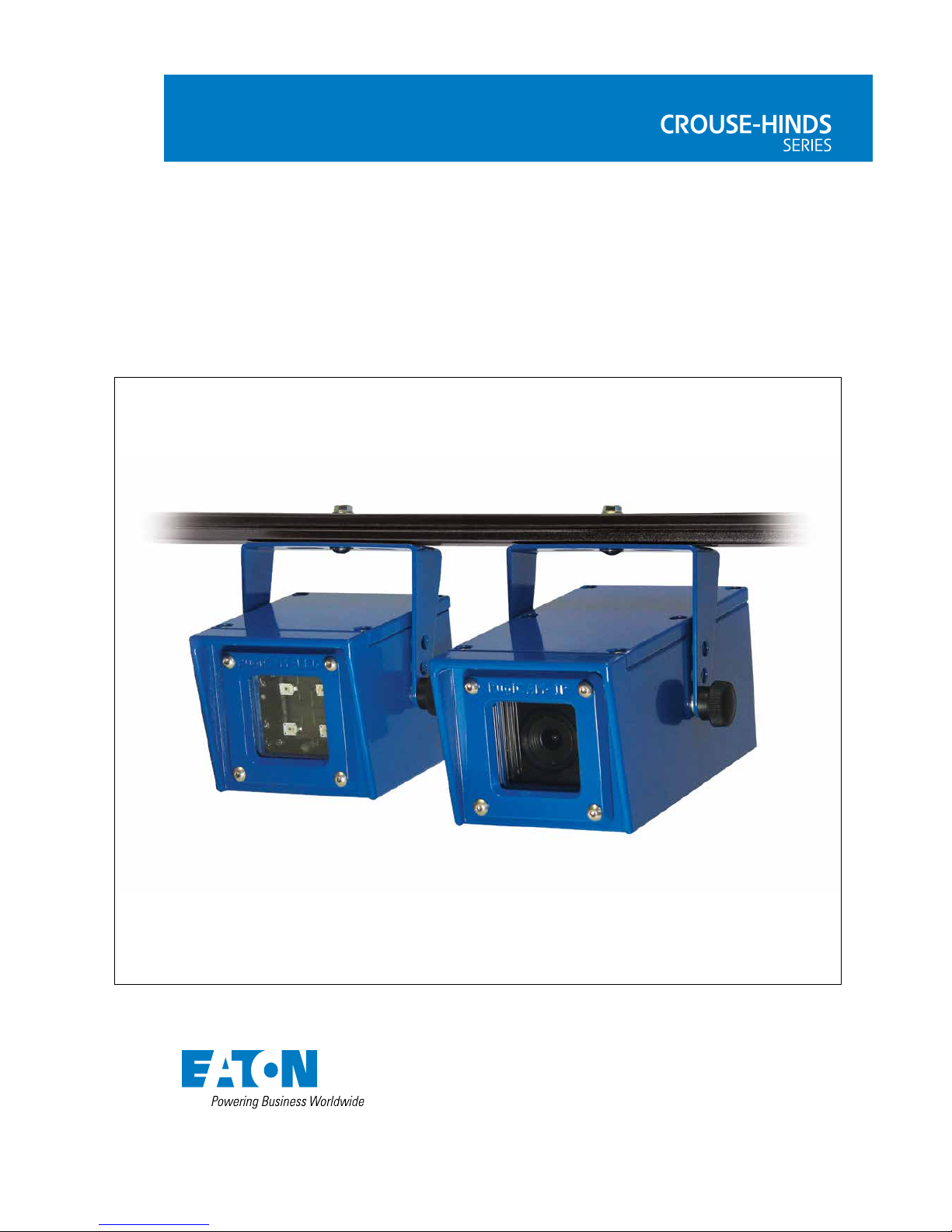
The RugiCAM-IP is an Intrinsically Safe IP Network Camera capable of producing high
quality colour video images at up to 1920x1080p at 30fps.
The H.264 compression technique ensures optimal bandwidth usage of the Ethernet
network and compatibility with all major video streaming players.
Optional LED lighting units are available to further enhance the cameras low light
capability where needed. These are available as either White LED or Infra-Red (IR)
LED types to suit the application, the IR type also having an ambient light sensor
that can automatically switch the camera to IR night mode (monochrome) whilst also
turning on all connected IR LED units.
The IP66 rated units are constructed from high quality anodised aluminium, powder
coated steel or stainless steel to suit different applications and environments and
contains a fully encapsulated camera (or LED) module. The resulting compact and
cost effective solution is suited to many HD video monitoring and surveillance
applications in and around the Hazardous Area.
The connections are made by multi-pin M12 plug and sockets on the rear of the
unit. This allows easy installation and maintenance in the event of a damaged cable
assembly.
2 FEATURES
• Resolution 1920x1080p, 1280x720, D1
• 1/2.8” SONY CMOS Sensor with Mega-Pixel 4mm f1.6 IR Lens
• H.264 Server with Adjustable Frame Rate - Controls Network
Bandwidth Usage (30fps max)
• Micro-SD Card slot (internal) 32GB max – for local recording on trigger events
• 10/100 IS Ethernet Interface supports up to 100m Cat5e/Cat6 Connection
• Wi-Fi (optional) supporting 802.11 b/g/n standards at up to 150Mbps
• 12VDC IS Power Supply Input or PoEx
TM
(Power over IS Ethernet)
• Plug & Socket Connections - shortens installation time
• Rugged IP66 rated Anodised Aluminium, Powder Coated Steel or Stainless
Steel Enclosure suitable for harsh environments
• Compact dimensions (Camera W:87xH:79xD:165mm / LED
W:87xH:79xD:105mm)
• Operating Temperature: -20ºC to +60ºC
• Intrinsically Safe ‘Ex ia’ Group I Mining M1 and Group IIB ATEX and IECEx
Certified for Gas and Dust.
• Zone 1/ Zone 21 Mounting (Zone 0 / Zone 20 with a suitable Ex ia
Power Supply)
NOTE
The unit is certified to operate safely at -40°C while the standard designed
operating/storage range is -20°C to +60°C, the unit will function at -40°C. Some
aspects of performance are not guaranteed by design at temperature below -20°C
(e.g. Wi-Fi range), additionally possible issues with condensation or frosting of the
glass window should be considered at low temperatures, both of these depend on
the actual installation and environment and may not affect all applications.
MTL RugiCAM-IP Intrinsically Safe
Network camera and LED lighting unit
2
INM MTL RugiCAM-IP Rev 5
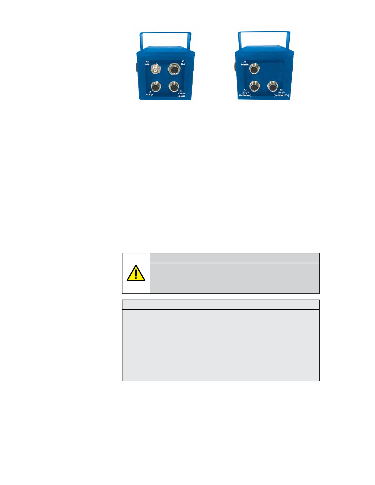
3 CONNECTIONS
CAMERA & LED UNITS
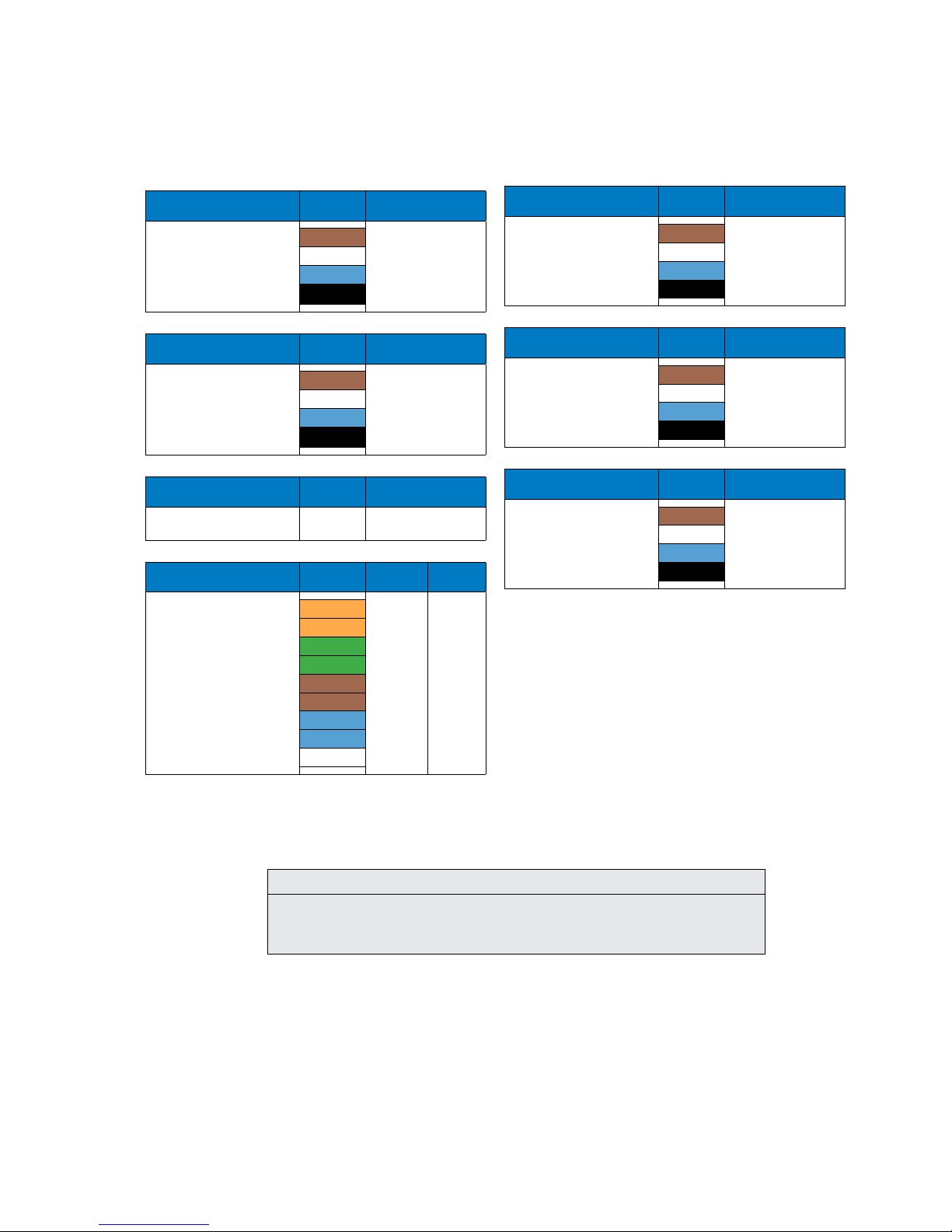
3.1 Camera Unit Connectors
12Vdc Power / RS485
X1 4 Pole M12 Connector (M)
Wire Colour Description
1 Brown
RS485 - A
RS485 - B
+12Vdc
0V
2 White
3 Blue
4 Black
LED Interface
X2 4 Pole M12 Connector (F)
Wire Colour Description
1 Brown
LED IN
LED OUT
-
0V
2 White
3 Blue
4 Black
WiFi Antenna
X4 TNC Connector
Description
2.4GHz Antenna
-
Ethernet LAN
X5 8 Pole M12 Connector
Wire Colour Description
RJ45
Connector
1 ORG-WHT Tx+ 1
2 ORG Tx- 2
3 GRN-WHT Rx+ 3
4 GRN Rx- 6
5 BRN-WH PoEx- 7
6 BRN PoEx- 8
7 BLU-WHT PoEx+ 5
8 BLU PoEx+ 4
shield screen GND shield
3.2 LED Unit Connectors
12Vdc Power
X1 4 Pole M12 Connector (M)
Wire Colour Description
1 Brown -
2 White -
3 Blue +12Vdc
4 Black 0V
LED Interface (To Camera)
X2 4 Pole M12 Connector (M)
Wire Colour Description
1 Brown LED OUT
2 White LED IN
3 Blue -
4 Black 0V
LED Interface (To Other LEDs)
X3 4 Pole M12 Connector (F)
Wire Colour Description
1 Brown -
2 White LED IN
3 Blue -
4 Black 0V
NOTE
The cable core colours as shown in the diagrams above are for reference if using an MTL
supplied cable assembly. Alternatively some cables may have black cores numbered 1-4
corresponding to the M12 connector pin #.
INM MTL RugiCAM-IP Rev 5
3
4 INSTALLATION
4.1 Camera Unit
The RugiCAM-IP is an Intrinsically Safe IP Network Camera capable of producing high
quality colour video images at up to 1920x1080p at 30fps.
The H.264 compression technique ensure optimal bandwidth usage of the Ethernet
network and compatibility with all major video streaming players.
Optional LED lighting units are available to further enhance the cameras low light
capability where needed. These are available as either White LED or Infra-Red (IR)
LED types to suit the application, the IR type also having an ambient light sensor
that can automatically switch the camera to IR night mode (monochrome) whilst also
turning on all connected IR LED units.
The IP66 rated units are constructed from high quality anodised aluminium, powder
coated steel or stainless steel to suit different applications and environments and
contains a fully encapsulated camera (or LED) module. The resulting compact and
cost effective solution is suited to many HD video monitoring and surveillance
applications in and around the Hazardous Area.
The connections are made by multi-pin M12 plug and sockets on the rear of the
unit. This allows easy installation and maintenance in the event of a damaged cable
assembly.
WARNING!
This equipment must be installed, operated and maintained only be trained
competent personnel and in accordance with all appropriate international,
national and local standard codes of practice and site regulation for intrinsically
safe apparatus and in accordance with the instructions contained here.
NOTE
Refer to the certificate for ‘Special Conditions of Safe use’. Copied below: -
The following conditions relate to safe installation and/or use of the equipment.
1. Versions of the enclosure can be manufactured from aluminium (part number includes AA –
Anodised Aluminium). In rare cases, ignition sources due to impact and friction sparks could
occur with this type of enclosure. This shall be considered during installation, particularly if the
equipment is installed in a Zone 0 or Group I (mining) location. If in doubt, use a stainless steel
(SS) or coated/painted steel (CS) enclosure.
2. If the enclosure is coated or painted then it must be installed in such a manner that the
danger of ignition of flammable dust due to propagating brush discharges is avoided.
4.2 LED Unit
• White led (colour temperature 6500k) unit. led angle 170degrees.
• IR led ( wavelength 850nm) unit. led angle 120degrees
• Each led unit requires an is power supply on connector x1
• LEDconnector x2 connects to camera connector x2 (day/night control by led
unit 1 sensor)
Camera Unit LED Unit
4
INM MTL RugiCAM-IP Rev 5
• Additional led units can be daisy-chained - led connector x3 connects to x2 on
next led unit
• The first LED units integral photo-resistive sensor allows the camera to
automatically switch to night mode (removes IR cut filter and sets
monochrome b/w mode) at low light levels, camera then switches on all
connected LED units. This depends on configuration to be set (section 5.4.5)
using photo-resistive sensor mode.
LED Unit
(when used standalone - without camera)
• With just a 12v supply connected LED unit lights up (~300mA). Application
could just switch the supply ON/OFF to control the light.
• If a link is fitted between pin IN to OUT then the light ON/OFF is controlled by
its internal light sensor
• If control pin IN is driven high (2V - 5V) this turns the light OFF, driving low
(0V) or open circuit this pin turns the light ON
5 CONNECTING THE RUGICAM-IP TO A PC
5.1 Internet Explorer
1. Connect IS power to the camera from a suitable IS power supply such as MTL
9492-PS-PLUS.
2. Connect the RugiCAM-IP to a PC with Ethernet cable via an IS isolator, such
as MTL 9468 -ET and power on the camera.
NOTES
Other Browsers are supported, they require an add on. For Chrome this can be
found at www.ietab.net.
Some older computers need a crossover cable if the NIC doesn’t have automatic
cable switching
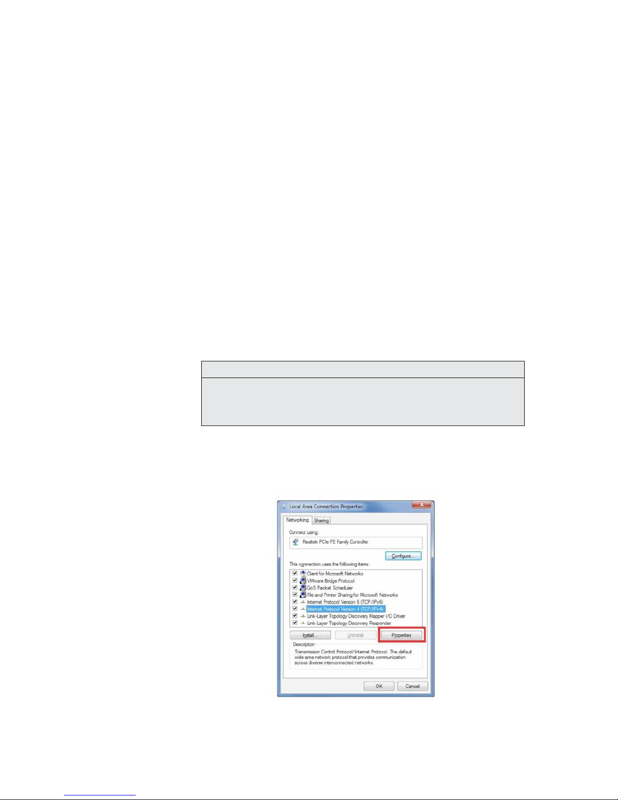
3. On Windows 7, go to Control Panel\Network and Sharing Center; Click
“Local Area Connection” and then click “Properties”. On Windows XP, go
to Control Panel\Network and Internet\Network Connections. Right click on
the corresponding Network adapter and then click “Properties”.
4. In Local Area Connection Properties, Click Internet Protocol Version 4
(TCP/ IPv4) Properties.
INM MTL RugiCAM-IP Rev 5
5
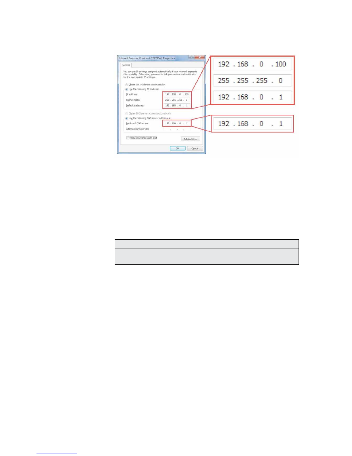
5. Specify IP address and DNS server as in the screenshot below.
6. If necessary, wait for around 45 seconds for the IP Camera to boot up.
7. Open Internet Explorer, browse for the IP address of the
Camera (http://192.168.0.168/).
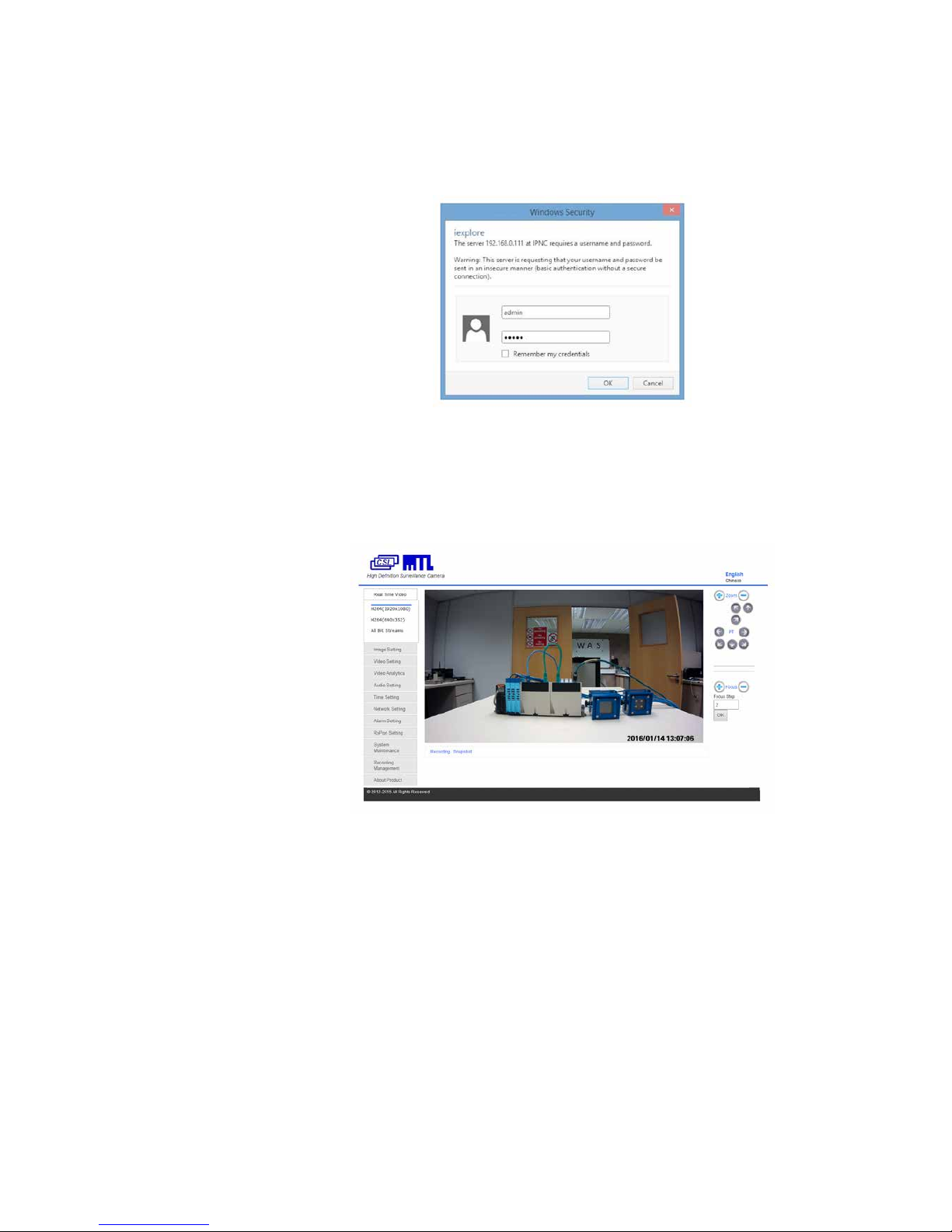
8. You should see a login Window where you can enter the username
and Password.
User Name: admin
Password: admin
9. If you run this camera at the first time, you may not be able to see the live
video before you install ActiveX. Please refer to Appendix A to install the
ActiveX control.
NOTE
The default IP address is static IP 192.168.0.168. You can change the static IP
address or set network setting to DHCP in Web Interface.
5.2 Connecting RugiCAM-IP to a Network
The IP Camera can also be connected to a network.
To connect the IP Camera to a network via a Router. Make sure the client PC with
correct OS is also connected to the same network.
Connect the external Power to the IP Camera.
The router will assign an IP address to the IP Camera.
The IP Camera will show up on the PC as a UPnP device. UPnP device can be found
in File Explorer>Network (left Pane)>Other Devices.
6
INM MTL RugiCAM-IP Rev 5
5.3 Accessing the Video Preview
To access the video preview, please follow the steps below:
1. Type the IP address into Internet Explorer (IE), and you will get asked for a
username and password.
2. In order to complete the installation of the Control successfully through the
browser, the version of IE must be upgraded to 6.0 or above.
3. Enter user Name: admin
4. Enter password: admin
5. Click “OK”. You will the get to the video preview as show below

INM MTL RugiCAM-IP Rev 5
7
6 IE INTERFACE OVERVIEW
The Window displays real-time video images, as shown in the picture above. The
Client interface includes:
• Live video Preview.
• Navigation interface.
As shown on the left side of the webpage above, shown in detail in
the diagram below.
• Recording and Snapshot:
NOTE
When using the Recording function, please run IE as Administrator.
• Recording:
Click the ‘Recording’ icon as shown below to start recording, the video
will be saved to your PC; Click the ‘Recording’ icon again, the video
recording will stop.
A window will pop up to show the path of the saved video.
NOTE
You may have to search for the file location of the saved video, as it may be
different to that stated, if permission for the location is denied by PC.
• Snapshot:
Click the ‘Snapshot’ icon as shown below, you will capture an image.
8
INM MTL RugiCAM-IP Rev 5
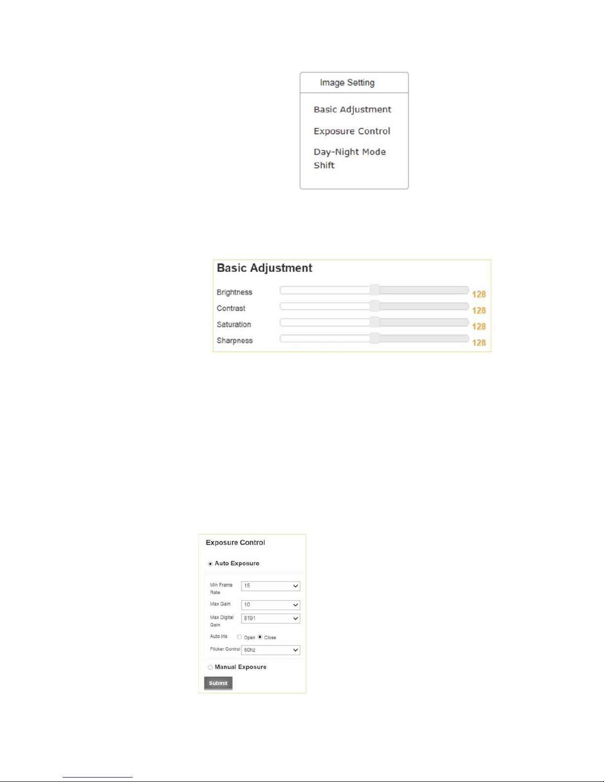
6.1 Image Setting
6.1.1 Basic Adjustment
6.1.1.1 Brightness
Scroll bar to control brightness. (value ranges from 1 to 255)
6.1.1.2 Contrast
Scroll bar to control contrast. (value ranges from 1 to 255)
6.1.1.3 Saturation
Scroll bar to control saturation. (value ranges from 1 to 255)
6.1.1.4 Sharpness
Scroll bar to control sharpness. (value ranges from 1 to 255)
6.1.2 Exposure Control
• Auto Exposure:
Click ‘Auto Exposure’ button to enable auto exposure
• Min Frame Rates are 30, 25, 15, 8, 1
• Max Gain Range is 1 to 10
• Max Digital Gains are 8191, 4096, 2048, 1024
• Auto Iris is Enable or Disable
• Flicker Control is 50 or 60 Hertz
• Manual Exposure enable button
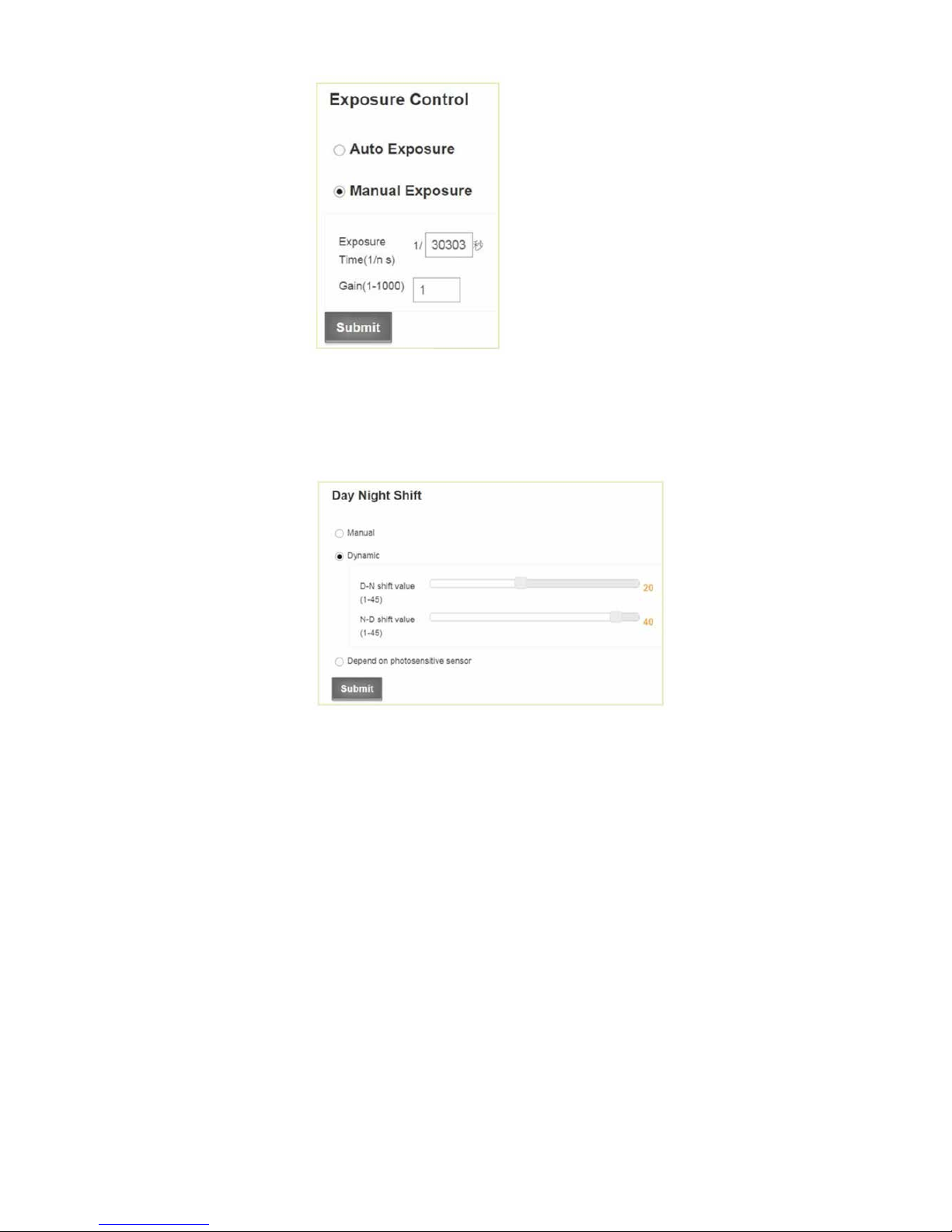
INM MTL RugiCAM-IP Rev 5
9
• Input Manual Exposure Time in nSec
• Input Exposure Gain 1 to 1000
6.1.3 Day-Night Mode Shift:
• Day-Night Mode Shift:
Click ‘Manual’ or the ‘Dynamic’ button to enable the required
exposure method
• Manual:
The day/night mode can be set manually.
• Day
• Night
• Dynamic:
The day/night mode can auto switch depending on the brightness.
• Min Brightness (1- 45):
when the brightness is lower than min, night mode will open.
• Max Brightness (1- 45):
when the brightness is higher than max, day mode will open.
• Depend on photosensitive sensor
Click button to enable the ‘Depend on photosensitive sensor’ setting.
• High When Day:
There is a photosensitive chip located on the IR LED board, in low light
conditions a signal will be sent to the CPU and the CPU will set the
camera to night mode.
• High When Night:
There is a photosensitive chip located on the IR LED board, in nightime
light conditions a signal will be sent to the CPU and the CPU will set
the camera to night mode.
10
INM MTL RugiCAM-IP Rev 5
6.2 Video Setting
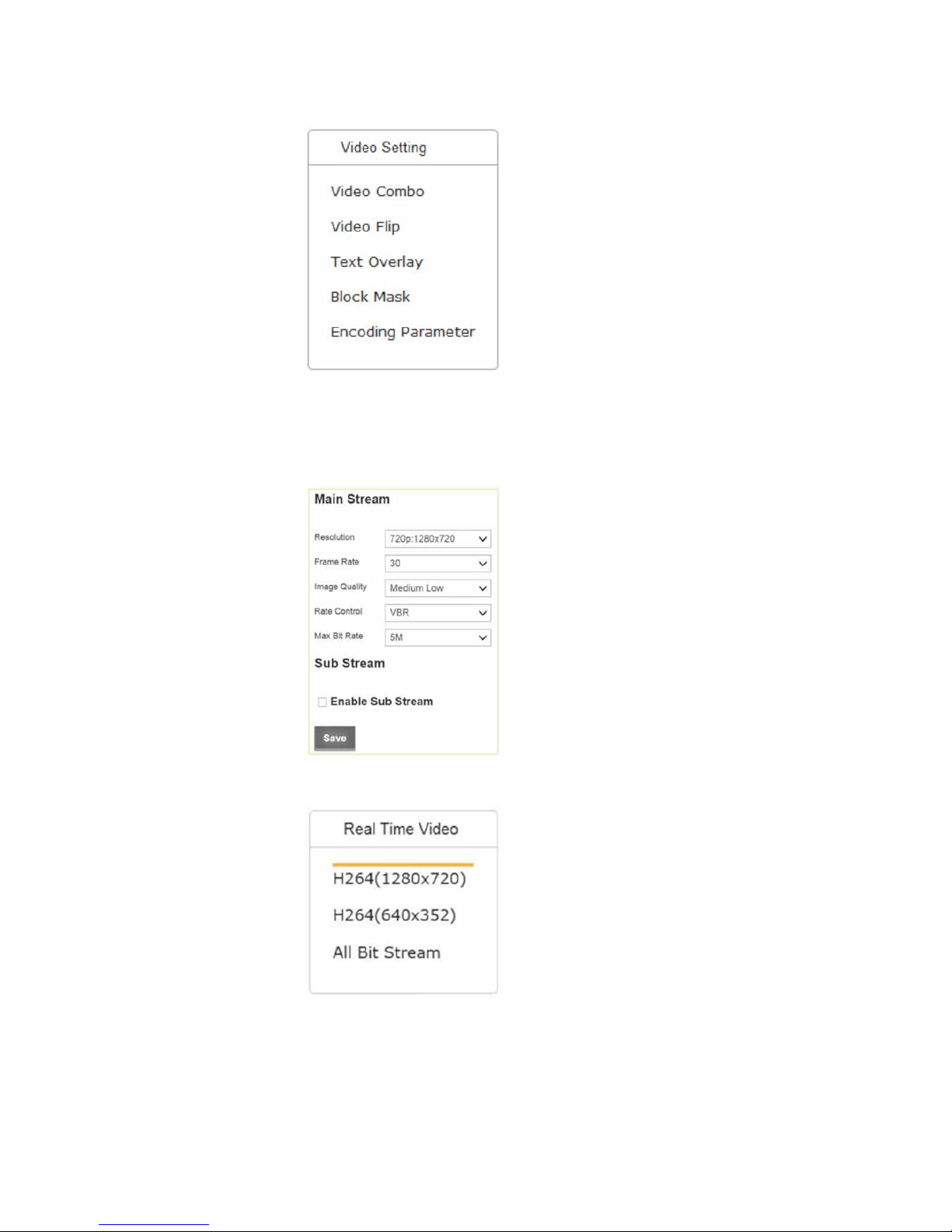
6.2.1 Video Combo
• Main Stream
• Resolution:
1080p: 1920x1080, 720p: 1280x720, D1: 704x576
• Frame Rate:
1 - 30
• Image Quality:
Very Low, Low, Medium Low, Medium, Medium
High and High
• Rate Control:
VBR (Variable Bit Rate) or CBR (Constant bit rate).
This option will alter how video is streamed from the
camera. VBR setting means constant video quality
at variable bandwidth. CBR setting means variable
video quality at a constant bandwidth.
• Maximum Bit-rate:
2M, 3M, 4M or 5M
• Enable the Sub Stream
After enabling the Sub stream, go to Real Time Video
and click the stream name to refresh it, you will get
two stream names.
All Bit Stream will get you 2 live videos.
INM MTL RugiCAM-IP Rev 5
11
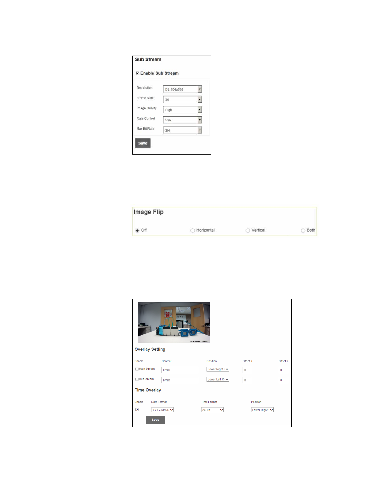
• Sub Stream
• Resolution:
D1: 704x576, VGA: 640x480, QVGA: 320x192
• Frame Rate:
1 to 30
• Image Quality:
Very Low, Low, Medium Low, Medium,
Medium High and High
• Rate Control:
VBR (Variable Bit Rate) or CBR (Constant bit
rate). This option will alter how video is
streamed from the camera. VBR setting means
constant video quality at variable bandwidth.
CBR setting means variable video quality at a
constant bandwidth.
• Maximum Bit-rate:
512K, 1M, 2M
6.2.2 Video Flip
Click buttons to make appropriate selection.
• Off
• Horizontal
• Vertical
• Both
6.2.3 Text Overlay
Click check box to make the appropriate selection.
• Main Stream overlay:
• Enable
• Text

12
INM MTL RugiCAM-IP Rev 5
• Position:
Use the pull-down list to choose Position.
• Lower-left corner
• Lower-right corner
• Upper-left corner
• Upper-right corner
• Offset X
Enter the appropriate offset setting.
• Offset Y
Enter the appropriate offset setting.
Click check box to make the appropriate selection.
• Sub Stream overlay:
• Enable
• Text
• Position:
• Lower-left corner
• Lower-right corner
• Upper-left corner
• Upper-right corner
• Offset X
Enter the appropriate offset setting.
• Offset Y
Enter the appropriate offset setting.
• Time overlay:
Click the Enable check box.
• Date Format:
Use the pull-down list to choose Date Format.
• YYYY/MM/DD
• MM/DD/YYYY
• DD/MM/YYYY
• Time Format:
Use the pull-down list to choose Time Format.
• 12 Hrs
• 24 Hrs
• Position:
Use the pull-down list to choose Position.
• Lower-left corner
• Lower-right corner
• Upper-left corner
• Upper-right corner
 Loading...