

Page 1
Instruction Leaflet IL01906008E
Effective March 2011
Instructions for Testing Magnum DS
Digitrips with the MTK2000 Test Kit
Contents
Description Page
1: Introduction . . . . . . . . . . . . . . . . . . . . . . . . . . . . 2
2: MTK2000 / Breaker Information . . . . . . . . . . . . 2
3: MTK2000 Setup . . . . . . . . . . . . . . . . . . . . . . . . 5
4: Testing the MDS 520 Digitrip Models . . . . . . . . 5
5: Testing the 1150 Digitrip Models . . . . . . . . . . . . 8
6: Troubleshooting . . . . . . . . . . . . . . . . . . . . . . . . 11
7: Customer Updates . . . . . . . . . . . . . . . . . . . . . 12
8: Additional Publications . . . . . . . . . . . . . . . . . . . 12
Appendix . . . . . . . . . . . . . . . . . . . . . . . . . . . . . . . 13
Page 2
Instruction Leaflet IL01906008E
Effective March 2011
Instructions for Testing Magnum DS
Digitrips with the MTK2000 Test Kit
Warning
Do not attempt to install or perform maintenance on equipment While it is energizeD. Death or severe personal injury
can result from contact With energizeD equipment. alWays
verify that no voltage is present before proceeDing With the
task anD alWays folloW generally accepteD safety proceDures. eaton is not liable for the mis-application or misinstallation of its proDucts.
important
the user is cautioneD to observe all of the recommenDations,
Warnings anD cautions relating to the safety of personnel
anD equipment, as Well as all general anD local health anD
safety laWs, coDes anD proceDures. the recommenDations anD
information containeD herein are baseD on eaton’s experience
anD juDgement, but shoulD not be consiDereD to be all-inclusive or covering every application or circumstance Which may
arise. if any questions arise, contact eaton for further information or instructions.
Warning
Do not test the trip unit While the breaker is in the “connecteD” position. breaker must be rackeD to the “test” position, or
removeD from the sWitchgear cell.
Section 1: Introduction
1.1 General Information
The MTK200 Trip Unit Test is used to test and verify the pickup levels
and time delay settings of a breaker’s trip unit. Scheduled testing of
the circuit breaker’s trip unit will help to ensure proper operation of
the breaker and will lead to safer and more efficient performance.
520 Digitrip Units: The MTK2000 Trip Unit Test it supports the 520
curves accept the short delay I
1150 Digitrip Units: The MTK 2000 Trip Unit Test Kit does not support the Long Delay I
curves or the IEEE curves.
4
T Short Delay Flat curve, or any of the IEC
2
T and ground I2T.
Section 2: MTK2000 / Breaker Information
2.1 MTK2000 Controls
The following are the identifications and functions of the MTK2000
controls. Any time these are referred to in the following portions of
this publication they will be in bold type as shown in the following
definitions
Power — Turns power on and off to the MTK2000.
Phase Select — Permits checking of all phase input circuits on the
Magnum breaker. Phase Select can be pressed at any time prior to
performing a test. Since all feed into a common pickup and timing
circuit, it is only necessary to use one phase to test all the solidstate circuitry functions. Current is applied through the selected
phase and returns to MTK2000 via the neutral element. It is only
necessary to use one circuit function (e.g., Long Delay) to verify that
each phase (A, B and C) performs similarly. The Phase Select button is also used as an accelerator when scrolling through numerical
entry fields and can be used to delete characters when entering the
breaker name.
Test Select — Cycles the MTK2000 through the steps of testing,
including date input and the various tests. (See Flowchart at back
of document)
Start — Test Select and Start both change menus, but when Start
is pushed it will cause action.
Cancel — When pressed, takes the MTK2000 back to the beginning
of the test sequence, it is also used to move to previous field when
entering text data. (See Flowchart at back of document). Pressing
Cancel twice will take the MTK2000 back to the main screen.
Up Arrow — Increments value.
Down Arrow — Decrements value.
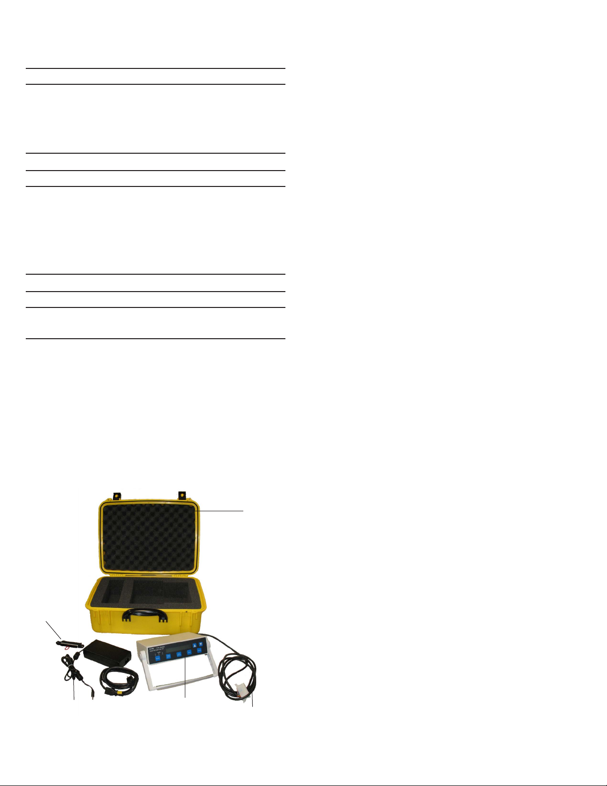
ZSI Shorting
Plugs
Power Supply
and Download
Figure 1. MTK2000 Test Kit
2
EATON CORPORATION www.eaton.com
PACB Tester
with SD Card
Case
MDS Trip
Unit Cable
Page 3

Instructions for Testing Magnum DS
Digitrips with the MTK2000 Test Kit
Instruction Leaflet IL01906008E
Effective March 2011
2.2 Digitrip Long Time Function
Testing of the Trip Unit must be performed with the Trip Unit properly
installed in the breaker. The Long Time function has a memory circuit with a reset time of 36 times the Long Delay Time. The thermal
memory jumper may need to be relocated to disable the thermal
memory. This jumper is shipped from the factory in the “active”
position. (Reference Section 2.3, MTK2000 Breaker Cables) If a trip
function LED on the Trip Unit is lit prior to a test, press the Trip Reset
pushbutton on the Trip Unit. When bench testing a breaker wired for
zone interlock applications, MDS shorting plug 8779C02G06 should
be installed. (Reference Section 2.3. MTK2000 Breaker Cables)
2.3 MTK2000 Breaker Cables
The MTK2000 MDS Breaker Cable is used to connect the MTK2000
to the breaker’s trip unit. Before the MDS 14 pin MTK2000 plug is
inserted into the Digitrip verify the Long Time Memory (LTM) jumper
is in the inactive position, or it is removed. If it is in the active position, it must be removed or returned to the inactive position before
the adapter connector can be inserted. It is important to note that
all tests must be performed with the LTM jumper in the “inactive”
position.
ote:N A physical jumper is used with 520 – 520MC Digitrips.
The 1150 is set differently than the 520 Digitrips; there is no LTM
jumper, the “Long Memory” function must be set to off.
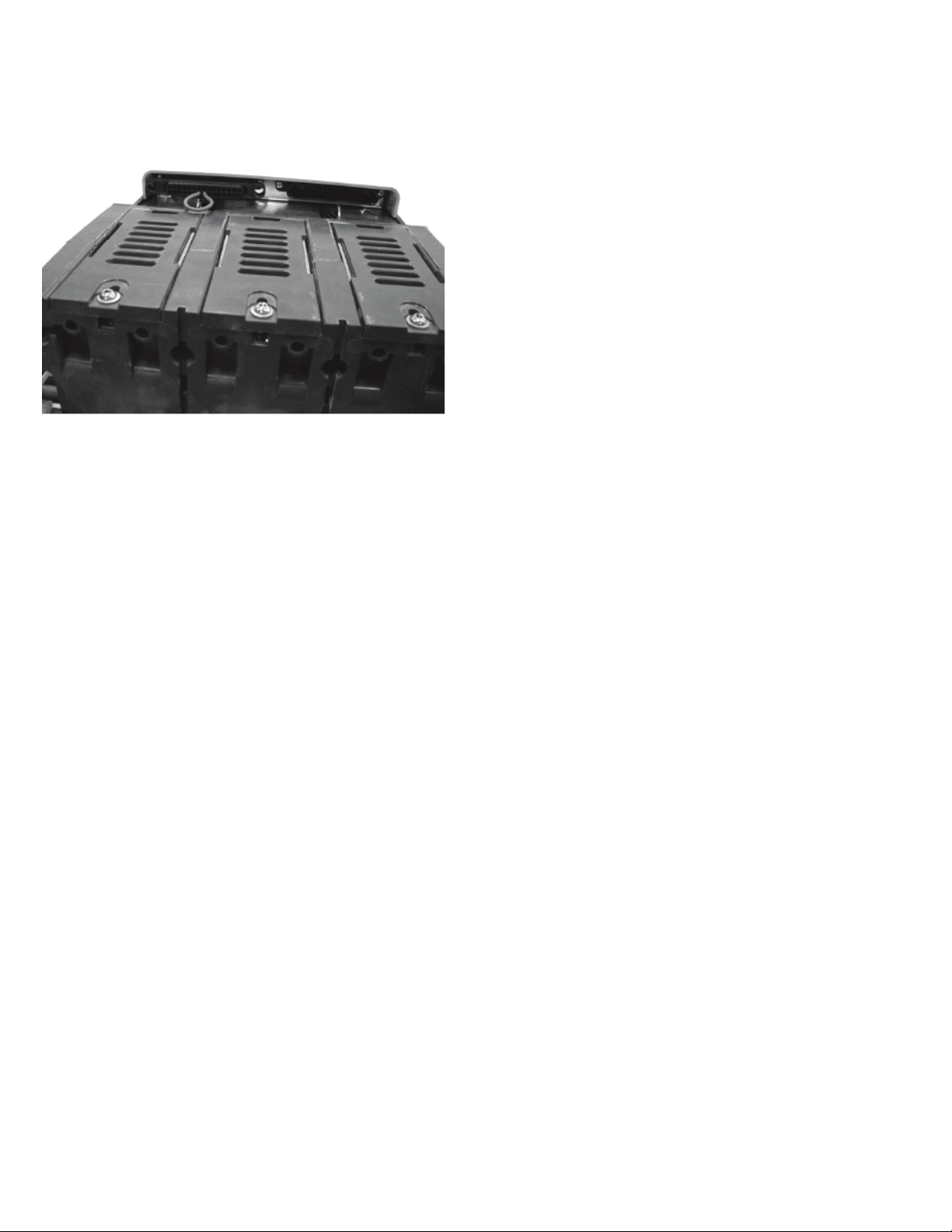
2.4 Zone Interlock Shorting Plug
The Zone Interlock Shorting Plug for the Magnum breaker
(8779C02G06) is required when the breaker is removed from the
switchgear cell for testing. The Shorting Plug must be installed on
the breaker secondary contacts to defeat zone-interlock wiring.
Figure 3. ZSI Shorting Plug
Figure 2. Magnum Test Port
EATON CORPORATION www.eaton.com
3
Page 4
Instruction Leaflet IL01906008E
Effective March 2011
Instructions for Testing Magnum DS
Digitrips with the MTK2000 Test Kit
Review the picture below for the installation of the Magnum
Shorting plug.
Figure 4. Magnum Shorting Plug
ote:N If the ZSI shorting plug is not in the circuit the ground fault time test
will go instantaneously. The short delay time test will go instantaneously.
2.5 Circuit Breaker Information
2.5.1 MTK2000 Tolerance Bands
The Long Delay Pickup point is normally set in the Digitrip at 110%
of the Long Delay Setting. The tolerance is ±5% of 110%. Long
Delay Times of the Trip Unit are top of band. The tolerance is
+0% /-30% of the Long Delay Time Setting. Short Delay Pickup,
Instantaneous, and Ground Fault Pickup values are mid-band, which
have ±10% tolerance. Short Delay Time and Ground Time require
curve for band tolerance.
2.5.2 Digitrip Test Guidelines
Testing of the Trip Unit must be performed with the Trip Unit properly
installed in the breaker. The Long Time function has a memory circuit with a reset time of 36 times the Long Delay Time. The thermal
memory jumper may need to be relocated to disable the thermal
memory. This jumper is shipped from the factory in the “active”
position. (Reference Section 2.3, MTK2000 Breaker Cables) If a trip
function LED on the Trip Unit is lit prior to a test, press the Trip Reset
pushbutton on the Trip Unit. When bench testing a breaker wired for
zone interlock applications, MDS shorting plug 8779C02G06 should
be installed (Reference Section 2.3, MTK2000 Breaker Cables).
4
EATON CORPORATION www.eaton.com
Page 5

Instructions for Testing Magnum DS
Digitrips with the MTK2000 Test Kit
Instruction Leaflet IL01906008E
Effective March 2011
Section 3: MTK2000 Setup
3.1 General Information
Place the MTK2000 on a stable surface prior to testing. The handle
can be rotated for ease of viewing and operation by pressing the
buttons on the sides of the handle and rotating the handle to the
desired angle (see Flowchart at back of document). When powering on, the MTK2000 will run a self diagnosis before displaying the
Home Screen (see Flowchart at back of document).
3.2 Hardware Connections
Insert the power supply into a standard 120V outlet and plug the
opposite end into the MTK2000. Plug the breaker cable into the
MTK2000 and insert the grooved end into the breaker trip unit.
Check the long time memory jumper position before plugging connector into test port.
3.3 Storing Test Results
The MTK2000 is capable of storing data obtained from multiple
tests on the included SD Card. These results can be downloaded
to a computer via the communication cable included in the kit or
by importing the data directly from the SD Card. This data is saved
automatically to the MTK2000 as each test is performed. Once the
memory is full, the MTK2000 automatically begins to write over the
first test in memory. Because calibration data is also stored on the
card, it is crucial to the operation of the MTK2000 that the information on the SD Card is never removed.
It is important to press the Cancel button twice after performing all
tests on one trip unit before proceeding to the next trip unit so that
a new breaker name can be entered.
3.4 Powering Up the MTK2000
Press Power on the MTK2000. Once the kit powers on, the selfdiagnosis has been completed and the kit is ready to test the trip
unit. Upon power up and following self-diagnosis, the MTK2000 will
display the Home Screen. Press Test Select.
3.5 Setting the Date & Time
Reference Flow Chart for this section in order to understand how
to modify the System Setting for the MTK2000, press the Down
Arrow immediately after the MTK2000 displays the Home Screen.
The Home Screen will read “System Settings –> Date & Time”.
Press Start to modify the date. Use the Up Arrow and Down
Arrow to modify values in each selection and press Test Select to
proceed. Once completed press Cancel to return to the Systems
Configuration menu. Pressing Cancel once more will return the
MTK2000 to the Home Screen.
3.6 Communication Settings
Reference Flow Chart for this section in order to understand how
to modify the System Setting for the MTK2000, press the Down
Arrow immediately after the MTK2000 displays the Home Screen.
Once “System Settings –> Date & Time” is displayed, press the
Down Arrow to verify “Communications” is displayed.
Press Start to modify these settings. Use the Up Arrow and Down
Arrow to modify values in each selection and press Test Select to
proceed. Once completed press Cancel to return to the Systems
Configuration menu. Pressing Cancel once more will return the
MTK2000 to the Home Screen.
Section 4: Testing the MDS 520 Digitrip
Models
4.1 Legend for MTK2000 testing with 520 Digitrips
g= entered ground value setting
GF= Ground Setting
i(A)= the entered instantaneous value setting
l(A)= the output current value for the MTK2000
(A)=
I
l
l
l
I
I
I
INST= Instantaneous
LDS= Long Delay Setting
LDT= Long Delay Time@6xlr
mm= limit for Maintenance mode reduction levels
mult= multiplying factor
MMODE= Maintenance Mode
n= Rating Plug Value
r= entered Long Delay Setting
R= the actual time the Digitrip tripped during the test
s= entered “Short Delay Setting” value setting
SDS= Short Delay Setting
SD= Short Delay Setting
SDT= Short Delay Time
T= entered time value for the MTK2000
T
T
T
4.2 Entering Breaker Name
The MTK2000 is capable of storing test results as each test is performed. For this reason, it is important to label the breakers subject
to test in the MTK2000 memory. When prompted for breaker name
on the display screen press Start then use the Up Arrow and Down
Arrow to change the character and Start button to advance to the
next character. The Cancel button can be pressed to move to the
previous field. The Phase Select button, when pressed, performs
the delete function. Once the entry is complete, press the Test
Select button to proceed.
x g
I
g
n
(A)= ln x i
i
(A)= lr x m
m
(A)= lr x mult
mult
(A)
= rated plug value (must match sensor rating, I
n
= (A) ln x r
r
(A)= lr x s
s
= entered time value for the “Ground Time”
g
= entered time value for the “Long Delay Time @6xlr”
r
= entered time value for the “Short Delay Time”
s
s
)
EATON CORPORATION www.eaton.com
5
Page 6

Instruction Leaflet IL01906008E
Effective March 2011
Instructions for Testing Magnum DS
Digitrips with the MTK2000 Test Kit
It is important to press the Cancel button twice to return to the
Home Screen after performing all tests on one breaker before proceeding to the next breaker so that a new breaker name can be
entered.
4.3 Setting the Rating Plug
Press Start to set the rating plug value on the MTK2000 by using
the scroll up and down button. Press Test Select button when com-
plete.
4.4 Setting the Frequency
Press Start to set the frequency value on the MTK2000 by using
the scroll Up and Down Arrow. Press Test Select button when
complete.
4.5 ZSI Shorting Plug
The MTK2000 will ask if the ZSI Shorting Plug is installed, please
validate if it is installed (Reference Section 2.4 Zone Interlock
Shorting Plug), if the correct answer is not shown, press Start then
scroll the up and down arrows to find the correct answer. Once
the correct answer is shown press Test Select.
ote:N If the shorting plug is present the short delay time and ground fault
time can be calculated by the MTK 2000.
If the shorting plug is not present and the answer to this query is
“Yes”; both the Short Delay Time and Ground Time test will “Fail”
on the MTK2000.
If the shorting plug is not present and the answer to this query is
“No”; both the Short Delay Time and Ground Time test will be a
“Pass” on the MTK2000.
4.6 Self Calibrate
This should be done for every MAGNUM breaker
Press Start
Once the calibration is complete the MTK2000 will say “Calibration
Complete” press Test Select to Return.
4.7 Long Delay Setting
4.7.1 MDS 520 Digitrip Models
If any of the red LEDs are blinking press “Reset” on Digitrip.
•
Set the desired test value for the “Long Delay Setting” dial.
•
Set values for the “Short Delay Setting” dial to the maximum
value.
•
Set values for the “Ground Setting” Dial to the maximum value.
•
Set for the “Instantaneous” dial to “OFF”.
While performing MTK2000 testing, please validate the LTM jumper
is in the “inactive” position. Reference Section 2.3 MTK2000
Breaker Cables.
4.7.2 MTK2000
“LONG DELAY TEST” should be shown on the screen if not press
Test Select until “LONG DELAY TEST” is on screen. Press Start.
The MTK2000 display is specifying that values need to be set, these
values were set in the Digitrip Instructions. Press Start.
Set “r” value on the MTK2000 display to match the Digitrip’s “Long
Delay Setting” dial by scrolling the up and down arrows.
Once value is set press Start on MTK2000, the test kit begins
to generate current. Begin to press the Up Arrow until the “Unit
Status” LED on the Digitrip begins to flash quickly. This should
occur at the Long Delay pickup current level. Once the pickup current value is found press the Start button. A message of “TEST
TERMINATED ->PASSED” or “TEST TERMINATED ->FAILED” will
appear on the MTK2000 display. The current level is the Long Delay
Pickup Value, this is the value where the trip unit will Start timing
for Long Delay (overload protection).
ote:N If the Start button is not pressed, the test times out after 40 seconds.
ote:N The rate of the Status LED flashing will slow to normal when the cur-
rent is lowered below the pickup setting.
4.8 Long Delay Time
4.8.1 MDS 520 Digitrip Models
If any of the red LED’s are blinking press “Reset” on Digitrip.
Do not change the “Long Delay Setting” dial.
Set the desired test value for the “Long Delay Time @6xIr” dial.
4.8.2 MTK2000
After the “LONG DELAY TEST” pick up current is found press Test
Select on the MTK2000.
ote:N If Test Select is hit more than once, the MTK will skip the next test
sequence. The only way to return to the time test is to redo the Long Delay
pick up current test.
The next value that needs to be set on the MTK2000 display is
“mult” the multiplier setting for the “Long Delay Time @6xIr”. (The
standard multiplier is 6 hence the statement “@6xIr”. If the multiplier
is changed lower than 6 the LD Time value goes up, if you raise the
multiplier higher the LD Time value goes down. When you leave the
multiplier as 6, the TR value and the LDT value stay the same.)
Press Test Select on MTK2000.
Set “Tr” value on the MTK2000 display to match the Digitrip’s “Long
Delay Time @6xIr” dial by scrolling the up and down arrows.
Once value is set press Start on MTK2000.
A message of “LONG DELAY PASSED” or “LONG DELAY FAILED”
will appear on the MTK2000 display.
4.9 Short Delay Settings
4.9.1 MDS 520 Digitrip Models
If any of the red LEDs are blinking press “Reset” on Digitrip.
•
Do not change the “Long Delay Setting” dial.
•
Set value on the “Long Delay Time @6xIr” dial to the maximum
value.
•
Set the desired test value for the “Short Delay Setting” dial.
•
Set value on the “Short Delay Time” dial to “.1” sec.
•
Set value on the “Instantaneous” dial to “OFF”.
6
EATON CORPORATION www.eaton.com
Page 7

Instructions for Testing Magnum DS
Digitrips with the MTK2000 Test Kit
Instruction Leaflet IL01906008E
Effective March 2011
4.9.2 MTK2000
Press Test Select until “SHORT DELAY TEST” name comes up.
Press Start.
The MTK2000 display is specifying that values need to be set, these
values were set in the Digitrip Instructions. Press Start.
Set the “s” value on the MTK2000 display to match the Digitrip’s
“Short Delay Setting” dial by scrolling the up and down arrows.
Once value is set press Start on MTK2000.
A message of “TRIP CURRENT FOUND –> PASSED” or “TRIP
CURRENT FOUND –> FAILED” will appear on the MTK2000 display.
4.10 Short Delay Time Settings
4.10.1 MDS 520 Digitrip Models
If red light is blinking press “Reset” on Digitrip.
Set the desired test value for the “Short Delay Time” dial.
ote:N Since this MTK2000 does not support the I2t curves the maximum no
values are supported by the MTK2000 past .5.
4.10.2 MTK2000
After the “SHORT DELAY TEST” current is found press Test Select
until “SHORT DELAY (at 1.5xs)” comes up on the MTK2000 display.
ote:N If Test Select is hit more than once, the MTK will skip the next test
sequence. The only way to return to the time test is to redo the Is Short
Delay pick-up current test.
Set the “Ts” value on the MTK2000 display to match the Digitrip’s
“Short Delay Time” dial by scrolling the up and down arrows.
Once value is set press Start on MTK2000.
A message of “SHORT DELAY PASSED” or “SHORT DELAY
FAILED” will appear on the MTK2000 display.
ote:N If test is failing please reference Section 2.3 MTK2000 Breaker Cables
4.11 Ground Settings
4.11.1 MDS 520 Digitrip Models
If any of the red LEDs are blinking press “Reset” on Digitrip.
•
Set values for the “Short Delay Setting” dial to the maximum
value.
•
Set the desired test value for the “Ground Setting” dial.
4.11.2 MTK2000
Press Test Select until “GROUND FAULT TEST” comes up on the
MTK2000. Press Start.
Set the “g” value on the MTK2000 display to match the Digitrip’s
“Ground Setting” dial by scrolling the up and down arrows.
Once value is set press Start on MTK2000.
ote:N The “g” value must not go above 1200Amps, please keep this in mind
when rating plugs are above 1200Amps.
A message of “TRIP CURRENT FOUND –> PASSED” or “TRIP
CURRENT FOUND –> FAILED” will appear on the MTK2000 display.
4.12 Ground Time Settings
4.12.1 MDS 520 Digitrip Models
If any of the red LEDs are blinking press “Reset” on Digitrip.
Set the desired test value for the “Ground Time” dial.
4.12.2 MTK2000
After the “GROUND FAULT TEST” current is found press Test Select
until “GF Delay” comes up on the MTK2000 display.
ote:N If Test Select is hit more than once, the MTK will skip the next test
sequence. The only way to return to the time test is to redo the Ig Ground
current Pick-up test.
Set the “Tg” value on the MTK2000 display to match the Digitrip’s
“Ground Time” dial by scrolling the up and down arrows.
Once value is set press Start on MTK2000.
A message of “GROUND FAULT PASSED” or “GROUND FAULT
FAILED” will appear on the MTK2000 display.
ote:N If test is failing please reference Section 2.3 MTK2000 Breaker Cables
4.13 Instantaneous Settings (If Applicable)
4.13.1 MDS 520 Digitrip Models
If red light is blinking press “Reset” on Digitrip.
•
Set value on the Long Delay dial to maximum.
•
Set value on the Long Delay Time dial to maximum.
•
Set value on the Short Delay Setting dial to M1.
•
Set value on the Short Delay Time dial to maximum.
•
Set the desired test value for the Instantaneous dial.
4.13.2 MTK2000
Press Test Select until “INSTANTANEOUS TEST” comes up on the
MTK2000. Press Start.
The MTK2000 display is specifying that values need to be set, these
values were set in the Digitrip Instructions. Press Start.
Set the “i” value on the MTK2000 display to match the Digitrip’s
“Instantaneous” settings by scrolling the up and down arrows.
Once value is set press Start on MTK2000.
A message of “TRIP CURRENT FOUND –> PASSED” or “TRIP
CURRENT FOUND –> FAILED” will appear on the MTK2000 display.
4.14 Instantaneous Time Settings
4.14.1 MDS 520 Digitrip Models
If any of the red LEDs are blinking on Digitrip press Reset.
4.14.2 MTK2000
After the “INSTANTANEOUS TEST” current is found press Test
Select until “INSTANT MAX TIME” comes up on the MTK2000 dis-
play.
ote:N If Test Select is hit more than once, the MTK will skip the next test
sequence. The only way to return to the time test is to redo the Ii current
test.
Press Start and the MTK2000 will return the Instantaneous trip
time.
A message of “INSTANTANEOUS PASSED” or “INSTANTANEOUS
FAILED” will appear on the MTK2000 display.
ote:N If test is failing please reference Section 2.3 MTK2000 Breaker Cables.
EATON CORPORATION www.eaton.com
7
Page 8

Instruction Leaflet IL01906008E
Effective March 2011
Instructions for Testing Magnum DS
Digitrips with the MTK2000 Test Kit
4.15 Maintenance Mode Setting
4.15.1 MDS520 Digitrip Models
If any of the red LEDs are blinking press “Reset” on Digitrip.
•
Set Maintenance Mode dial “On”
•
Set R value on the dial below the Maintenance Mode “On” Dial.
•
Set value on the Long Delay dial to maximum.
•
Set value on the Long Delay Time dial to maximum.
•
Set value on the Short Delay Setting dial to maximum.
4.15.2 MTK2000
Press Test Select until “MAINTENANCE MODE TEST” comes up on
the MTK2000. Press Start.
The MTK2000 display is specifying that values need to be set, these
values were set in the Digitrip Instructions. Press Start.
Set the “R” value on the MTK2000 display to match the Digitrip’s
Maintenance Mode R values by scrolling the up and down arrows.
ote:N If you are not sure which R value is needed the next menu will allow
the multiplier value to be set.
Press Test Select for “MMODE TRIP SET” menu, the “mm” value
can be adjusted up or down to give you the R value desired for testing.
Once value is set press Start on MTK2000.
A message of “TRIP CURRENT FOUND –> PASSED” or “TRIP
CURRENT FOUND –> FAILED” will appear on the MTK2000 display.
4.16 Maintenance Mode Time Settings
4.16.1 MDS 520 Digitrip Models
If any of the red LEDs are blinking on Digitrip press Reset.
4.16.2 MTK2000
After the “MAINTENANCE MODE” current is found press Test
Select until “MMODE MAX TIME” comes up on the MTK2000 dis-
play.
ote:N If Test Select is hit more than twice, the MTK will skip the next test
sequence. The only way to return to the time test is to redo the Im current
test.
Press Start and the MTK2000 will return the Maintenance Mode trip
time.
A message of “MAINTENANCE PASSED” or “MAINTENANCE
FAILED” will appear on the MTK2000 display.
If test is failing please reference Section 2.3 MTK2000 Breaker
Cables.
Section 5: Testing the 1150 Digitrip Models
5.1 Legend for MTK2000 testing with 1150 Digitrips
g= entered ground value setting
GF= GND PU
i(A)= the entered instantaneous value setting
l(A)= the output current value for the MTK2000 tested
(A)=
I
l
l
l
I
I
I
INST= INST PU
LDS= LONG PU
LDT= LongTIME
mm= limit for Maintenance mode reduction levels
mult= multiplying factor
MMODE= Maintenance Mode
n= Rating Plug Value
r= Long PU
R= the actual time the Digitrip tripped during the test
s= SHORT PU
SDS or SD= SHORT PU
SDT= SHORT TIME
T= is the entered time value the MTK2000 started a time test at
T
T
T
5.2 Entering Breaker Name
The MTK2000 is capable of storing test results as each test is performed. For this reason, it is important to label the breakers subject
to test in the MTK2000 memory. When prompted for breaker name
on the display screen press Start then use the Up Arrow and Down
Arrow to change the character and Start button to advance to the
next character. The Cancel button can be pressed to move to the
previous field. The Phase Select button, when pressed, performs
the delete function. Once the entry is complete, press the Test
Select button to proceed.
It is important to press the Cancel button twice to return to the
Home Screen after performing all tests on one breaker before proceeding to the next breaker so that a new breaker name can be
entered.
x g
I
g
n
(A)= ln x i
i
(A)= lr x m
m
(A)= lr x mult
mult
(A)
= rated plug value (must match sensor rating, I
n
= (A) ln x r
r
(A)= lr x s
s
= entered time value for the “GROUND TIME”
g
= entered time value for the “LongTIME”
r
= entered time value for the “SHORT TIME”
s
)
s
8
EATON CORPORATION www.eaton.com
Page 9

Instructions for Testing Magnum DS
Digitrips with the MTK2000 Test Kit
Instruction Leaflet IL01906008E
Effective March 2011
5.3 Setting the Rating Plug
Press Start to set the rating plug value on the MTK2000 by using
the scroll up and down button. Press Test Select button when com-
plete.
5.4 Setting the Frequency
Press Start to set the frequency value on the MTK2000 by using
the scroll Up and Down Arrow. Press Test Select button when
complete.
5.5 ZSI Shorting Plug
The MTK2000 will ask if the ZSI Shorting Plug is installed, please
validate if it is installed (Reference Section 2.4 Zone Interlock
Shorting Plug), if the correct answer is not shown, press Start then
scroll the up and down arrows to find the correct answer. Once
the correct answer is shown press Test Select.
ote:N If the shorting plug is present the short delay time and ground fault
time can be calculated by the MTK 2000.
If the shorting plug is not present and the answer to this query is
“Yes”; both the Short Delay Time and Ground Time test will “Fail”
on the MTK2000.
If the shorting plug is not present and the answer to this query is
“No”; both the Short Delay Time and Ground Time test will be a
“Pass” on the MTK2000.
5.6 Self Calibrate
This should be done for every MAGNUM breaker
Press Start
Once the calibration is complete the MTK2000 will say “Calibration
Complete” press Test Select to Return.
5.7 Long Delay Setting
5.7.1 MDS Digitrip Models
If any of the red LEDs are blinking press “Reset” on Digitrip.
Set value for the “LONG Slope” function to “I
ote:N The MTK2000 is not programmed to test the Long Delay I4T or IEEE or
IEC slopes.
2
T”.
Set the desired test value for the “LONG PU” function.
For test purposes set the “Long Memory” function is set to “OFF ”,
Reference Section 2.3 MTK200 Breaker Cables.
Set value for the “SHORT SLOPE” to “FLAT”.
ote:N The MTK2000 is not programmed to test Short Delay with I2T slope.
•
Set value for the “SHORT PU” function to maximum value.
•
Set value for the “INST PU” function to “OFF”.
•
Set value for the “GND PU” function to maximum value.
•
Set value for the “GND SLOPE” function to “FLAT”.
2
The MTK2000 is not programmed to test GROUND Delay with I
T slope.
Once all selections have been made, press “Save” under the “Edit
Value” Menus buttons.
5.7.2 MTK2000
“LONG DELAY TEST” should be shown on the screen if not press
Test Select until “LONG DELAY TEST” is on screen. Press Start.
The MTK2000 display is specifying that values need to be set, these
values were set in the Digitrip Instructions. Press Start.
Set “r” value on the MTK2000 display to match the Digitrip’s “Long
PU” settings by scrolling the up and down arrows.
Once value is set press Start on MTK2000, the test kit begins to
generate current. Begin to press the Up Arrow until the “Unit
Status” LED on the Digitrip begins to flash quickly. This should
occur at the pickup current. Once the pickup current value is
found press the Start button. A message of “TEST TERMINATED
->PASSED” or “TEST TERMINATED ->FAILED” will appear on the
MTK2000 display. The current level is the Long Delay Pickup Value,
this is the value where the trip unit will Start timing for Long Delay
(overload protection).
ote:N If the Start button is not pressed, the test times out after 40 seconds.
ote:N The rate of the Status LED flashing will slow to normal when the cur-
rent is lowered below the pickup setting.
5.8 Long Delay Time
5.8.1 MDS 1150 Digitrip Models
If any of the red LEDs are blinking press “Reset” on Digitrip.
Do not change the “LONG PU” function.
In the Program Settings menu set the desired test value for the
“LongTIME” function.
Once all selections have been made, press “Save” under the “Edit
Value” Menus buttons.
5.8.2 MTK2000
After the “LONG DELAY TEST” pick up current is found press Test
Select on the MTK2000.
ote:N If Test Select is hit more than once, the MTK will skip the next test
sequence. The only way to return to the time test is to redo the Long Delay
pick up current test.
The next value that needs to be set on the MTK2000 display is
“mult” the multiplier setting for the “Long Delay Time @6xIr”. (The
standard multiplier is 6 hence the statement “@6xIr”. If the multiplier
is changed lower than 6 the actual LDT value goes up, if you raise
the multiplier higher the actual LDT value goes down. When you
leave the multiplier as 6, the TR value and the LDT value stay the
same.)
Press Test Select on MTK2000.
Set “Tr” value on the MTK2000 display to match the Digirip’s
“LongTIME” value by scrolling the up and down arrows.
Once value is set press Start on MTK2000.
A message of “LONG DELAY PASSED” or “LONG DELAY FAILED”
will appear on the MTK2000 display.
5.9 Short Delay Settings
5.9.1 MDS 520 1150 Digitrip Models
If any of the red LEDs are blinking press “Reset” on Digitrip..
•
Do not change the “LONG PU” function.
•
Set value for the “LongTIME” function to maximum.
•
Set the desired test value for the “SHORT PU” function.
•
Set value for the “SHORT TIME” function to “.1” sec.
•
Set value for the “INST PU” function to “OFF”.
Once all selections have been made, press “Save” under the “Edit
Value” Menus buttons.
EATON CORPORATION www.eaton.com
9
Page 10

Instruction Leaflet IL01906008E
Effective March 2011
Instructions for Testing Magnum DS
Digitrips with the MTK2000 Test Kit
5.9.2 MTK2000
Press Test Select until “SHORT DELAY TEST” name comes up.
Press Start.
The MTK2000 display is specifying that values need to be set, these
values were set in the Digitrip Instructions. Press Start.
Set the “s” value on the MTK2000 display to match the Digitrip’s
“SHORT PU” value by scrolling the up and down arrows.
Once value is set press Start on MTK2000.
A message of “TRIP CURRENT FOUND –> PASSED” or “TRIP
CURRENT FOUND –> FAILED” will appear on the MTK2000 display.
5.10 Short Delay Time Settings
5.10.1 MDS 1150 Digitrip Models
If any of the red LEDs are blinking press “Reset” on Digitrip.
Set the desired test value for the “SHORT TIME” function.
Once selection has been made, press “Save” under the “Edit Value”
Menus buttons.
5.10.2 MTK2000
After the “SHORT DELAY TEST” current is found press Test Select
until “SHORT DELAY (at 1.5xs)” comes up on the MTK2000 display.
ote:N If Test Select is hit more than once, the MTK will skip the next test
sequence. The only way to return to the time test is to redo the Is Short
Delay Pick-up current test.
Set the “Ts” value on the MTK2000 display to match the Digitrip’s
“Short TIME” values by scrolling the up and down arrows.
Once value is set press Start on MTK2000.
A message of “SHORT DELAY PASSED” or “SHORT DELAY
FAILED” will appear on the MTK2000 display.
ote:N If test is failing please reference Section 2.3 MTK2000 Breaker Cables.
5.11 Ground Settings
5.11.1 MDS 1150 Digitrip Models
If any of the red LEDs are blinking press “Reset” on Digitrip.
•
Set the “SHORT PU” function to maximum.
•
Set the desired test value for the “GND PU” function.
Once selection has been made, press “Save” under the “Edit Value”
Menus buttons.
5.11.2 MTK2000
Press Test Select until “GROUND FAULT TEST” comes up on the
MTK2000. Press Start.
Set the “g” value on the MTK2000 display to match the Digitrip’s
“Ground PU” values by scrolling the up and down arrows.
Once value is set press Start on MTK2000.
ote:N The “g” value must not go above 1200Amps, please keep this in mind
when rating plugs are above 1200Amps.
A message of “TRIP CURRENT FOUND –> PASSED” or “TRIP
CURRENT FOUND –> FAILED” will appear on the MTK2000 display.
5.12 Ground Time Settings
5.12.1 MDS 1150 Digitrip Models
If any of the red LEDs are blinking press “Reset” on Digitrip.
Set the desired test value for the “GROUND TIME” function.
Once selection has been made, press “Save” under the “Edit Value”
Menus buttons.
5.12.2 MTK2000
After the “GROUND FAULT TEST” current is found press Test Select
until “GF Delay” comes up on the MTK2000 display.
ote:N If Test Select is hit more than once, the MTK will skip the next test
sequence. The only way to return to the time test is to redo the Ig Ground
current Pick-up test.
Set the “Tg” value on the MTK2000 display to match the Digitrip’s
“GND TIME” values by scrolling the up and down arrows.
Once value is set press Start on MTK2000.
A message of “GROUND FAULT PASSED” or “GROUND FAULT
FAILED” will appear on the MTK2000 display.
ote:N If test is failing please reference Section 2.3 MTK2000 Breaker Cables.
5.13 Instantaneous Settings (If Applicable)
5.13.1 MDS 1150 Digitrip Models
If any of the red LEDs are blinking press “Reset” on Digitrip.
•
Set value for the “LONG PU” function to maximum.
•
Set value for the “LongTIME” function to maximum.
•
Set value for the “SHORT PU” function to maximum.
•
Set value for the “INST PU” function to “ON”.
•
Set the desired test value for the “INST PU” function.
Once selection has been made, press “Save” under the “Edit Value”
Menus buttons.
5.13.2 MTK2000
Press Test Select until “INSTANTANEOUS TEST” comes up on the
MTK2000. Press Start.
The MTK2000 display is specifying that values need to be set, these
values were set in the Digitrip Instructions. Press Start.
Set the “i” value on the MTK2000 display to match the Digitrip’s
“INST PU” settings by scrolling the up and down arrows.
Once value is set press Start on MTK2000.
A message of “TRIP CURRENT FOUND –> PASSED” or “TRIP
CURRENT FOUND –> FAILED” will appear on the MTK2000 display.
5.14 Instantaneous Time Settings
5.14.1 MDS 1150 Digitrip Models
If any of the red LEDs are blinking press “Reset” on Digitrip.
5.14.2 MTK2000
After the “INSTANTANEOUS TEST” current is found press Test
Select until “INSTANT MAX TIME” comes up on the MTK2000 dis-
play.
ote:N If Test Select is hit more than once, the MTK will skip the next test
sequence. The only way to return to the time test is to redo the Ii current
test.
Press Start and the MTK2000 will return the Instantaneous trip
time.
A message of “INSTANTANEOUS PASSED” or “INSTANTANEOUS
FAILED” will appear on the MTK2000 display.
ote:N If test is failing please reference Section 2.3 MTK2000 Breaker Cables.
10
EATON CORPORATION www.eaton.com
Page 11

Instructions for Testing Magnum DS
Digitrips with the MTK2000 Test Kit
Instruction Leaflet IL01906008E
Effective March 2011
5.15 Maintenance Mode Setting
5.15.1 MDS 1150 Digitrip Models
If any of the red LEDs are blinking press “Reset” on Digitrip.
•
Set the desired test value for the “Maint PU” funtion.
•
Set the “MaintenanceMode” menu to “Enable”.
Once selection has been made, press “Save” under the “Edit Value”
Menus buttons.
•
Set value for the “LONG PU” function to maximum.
•
Set value for the “LongTIME” function to maximum.
•
Set value for the “SHORT PU” function to maximum.
Once selection has been made, press “Save” under the “Edit Value”
Menus buttons.
5.15.2 MTK2000
Press Test Select until “MAINTENANCE MODE TEST” comes up on
the MTK2000. Press Start.
The MTK2000 display is specifying that values need to be set, these
values were set in the Digitrip Instructions. Press Start.
Set the “R” value on the MTK2000 display to match the Digitrip’s
“MAINT PU” values by scrolling the up and down arrows.
ote:N If you are not sure which R value is needed the next menu will allow
the multiplier value to be set.
Press Test Select for “MMODE TRIP SET” menu, the “mm” value
can be adjusted up or down to give you the R value desired for testing.
Once value is set press Start on MTK2000.
A message of “TRIP CURRENT FOUND –> PASSED” or “TRIP
CURRENT FOUND –> FAILED” will appear on the MTK2000 display.
5.16 Maintenance Mode Time Settings
5.16.1 MDS 1150 Digitrip Models
If any of the red LEDs are blinking press “Reset” on Digitrip.
5.16.2 MTK2000
After the “MAINTENANCE MODE” current is found press Test
Select until “MMODE MAX TIME” comes up on the MTK2000 dis-
play.
ote:N If Test Select is hit more than twice, the MTK will skip the next test
sequence. The only way to return to the time test is to redo the Im current
test.
Press Start and the MTK2000 will return the Maintenance Mode trip
time.
A message of “MAINTENANCE PASSED” or “MAINTENANCE
FAILED” will appear on the MTK2000 display.
ote:N If test is failing please reference Section 2.3 MTK2000 Breaker Cables.
Section 6: Troubleshooting
Listed below are resolutions to common problems experienced with
MTK2000. Please review this section prior to contacting Eaton with
questions.
Trip Unit keeps indicating the wrong type of trip (i.e. Long Delay
Trip when testing Short Delay Pickup).
Verify that the trip unit is set correctly as indicated on the MTK2000
prior to Starting the test and that the trip unit is reset prior to
Starting a test. Verify that the Zone Interlock plug is installed when
the breaker is removed past the Test Position or is removed from the
cell.
Measured values for a particular Digitrip are not consistent with
settings on the Digitrip.
Press Cancel twice to reach the Home Screen. Proceed as normal
and ensure that the MTK2000 performs the self calibration procedure with the new Digitrip. Verify that the thermal memory jumper is
in the correct position or setting (see paragraph 2.2.2). Ensure that
the SD Card provided from the factory is installed in the MTK2000
and still has the original calibration data stored.
Digitrip seems not to respond to input from the MTK2000.
Verify that the Digitrip Cable is plugged correctly into the Digitrip as
well as the rear of the MTK2000.
Long Delay Times seem to decrease during testing.
Verify that the thermal memory jumper is in the correct position (see
paragraph 2.2.2)
The values on the MTK2000 Test Kit and the values on my
metering Digitrip do not match.
It is important to understand that the Digitrip has a tolerance band
within which it is expected to perform. Some difference is acceptable, although this value should be minimal.
EATON CORPORATION www.eaton.com
11
Page 12

Instruction Leaflet IL01906008E
Effective March 2011
Instructions for Testing Magnum DS
Digitrips with the MTK2000 Test Kit
Section 7: Customer Updates
Periodically Eaton will issue updates that can be obtained at the following web address.
http://www.eaton.com/EatonCom/Markets/Electrical/Products/
Switchgear/LowVoltageSwitchgear/index.html
These updates are meant to resolve issues as well as improve functionality and usability of the MTK2000 Test Kit. These updates
are to be performed by the MTK2000 Test Kit user using the
included data communication cable.
Please visit the web site prior to testing to ensure the latest firmware revision has been installed on the PACB Trip Unit Test Kit.
Detailed instructions will be provided in the downloadable file guiding the user through the update procedure.
Section 8: Additional Publications
In addition to this Instruction Book, the following Instruction Books
and drawings are commonly included with any Magnum DS® Circuit
Breaker and/or provided with any Eaton Low-Voltage Assembly shipment. Please inspect the documentation provided before contacting
an Eaton service representative for replacements.
IB 2C12060H08 Instructions for Installation, Operation and
Maintenance of Magnum DS, DSX and DSL Low
Voltage Power Circuit Breakers
IB 2C12063H02 Instructions for Installation, Operation and
Maintenance of Magnum SB Insulated Case Low
Voltage Power Circuit Breakers
IL 70C1036H05 Instructions for Digitrip Models 1150, 1150i and
1150+,1150+i Trip Units for use only in CutlerHammer Magnum and Magnum DS Circuit
Breakers
IL 70C1037H05 Digitrip models 520, 520i; and 520M, 520Mi,
520MC, 520MCi trip units for use only in Magnum
and Magnum DS circuit breakers
70C1082 Characteristic Curves for Magnum DS Circuit
Breakers using Digitrip 220, 220Pm 520, 520M
Tripunits and Magnum Circuit Breakers using
Digitrip 520i, 520Mi, 520MCi Tripunits
70C1030 Characteristic Curves for Magnum DS and
Magnum SB Circuit Breakers using Digitrip 1150
and Magnum Circuit Breakers using 1150i Tripunits
12
EATON CORPORATION www.eaton.com
Page 13

Instructions for Testing Magnum DS
Digitrips with the MTK2000 Test Kit
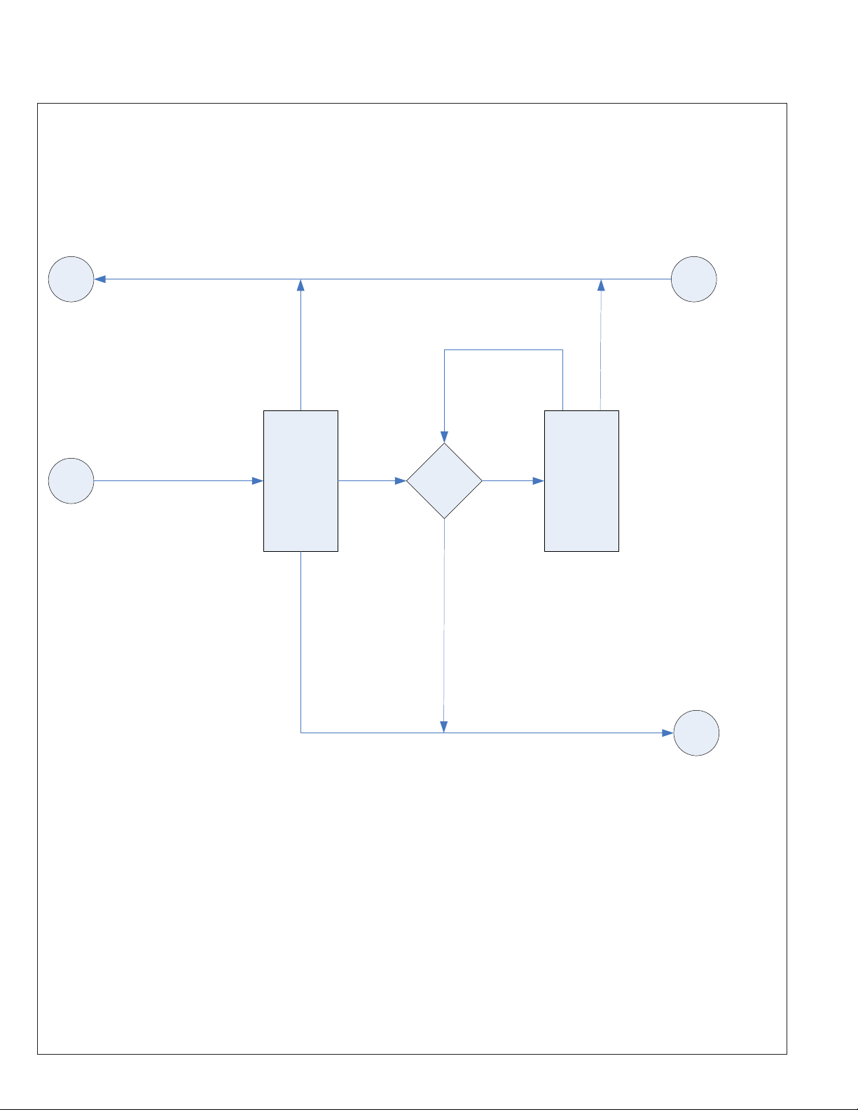
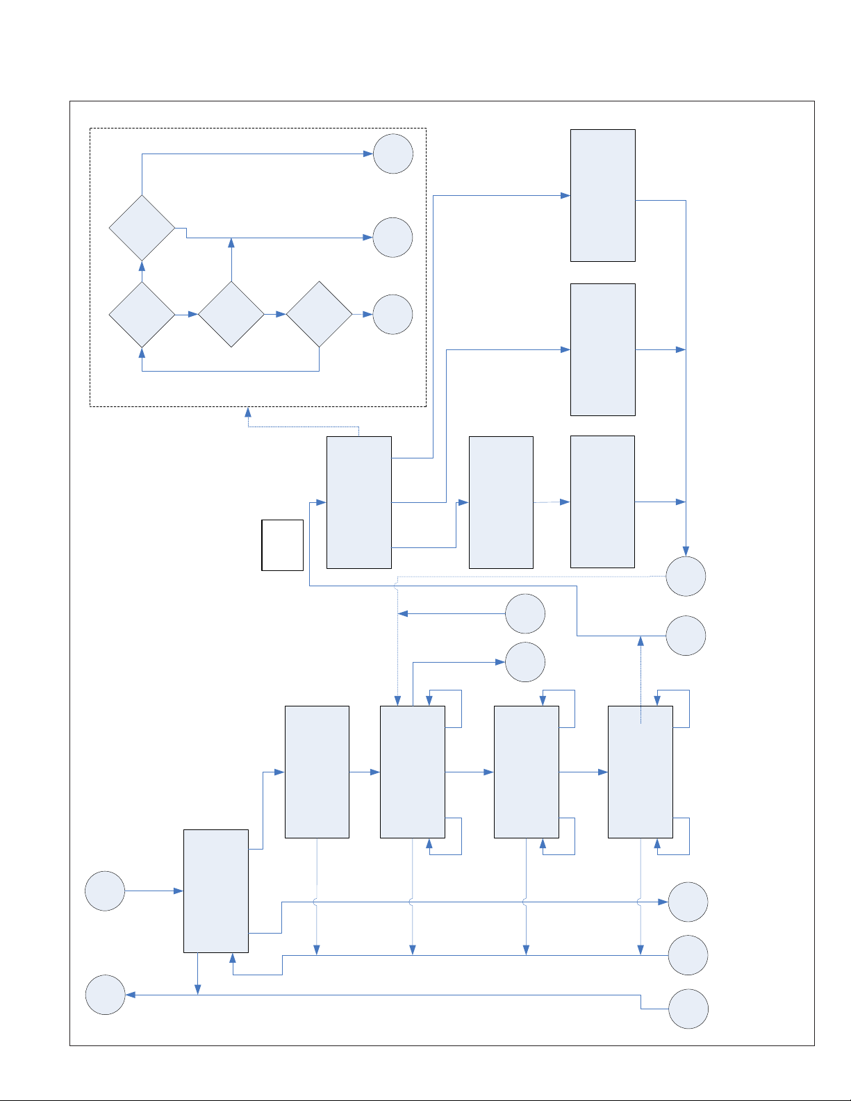
Appendix
Instruction Leaflet IL01906008E
Effective March 2011
C
Cancel
next Channel
Increment Phase to
No
Yes
NRX?
Yes
Phase
No
Button?
Down Arrow (Change Value)
Up Arrow (Change Value)
> MAGNUM
Up Arrow (Increment Character Value)
Down Arrow (Increment Character Value)
Down Arrow (Change Value)
>XXXXXXXX
Start: Increment to Next Character Position
Cancel: Move to Previous Character Position
Up Arrow (Change Value)
> 6300 A | 6000 A | 5000 A | 4000 A … 250 A | 200 A | 100 A
Down Arrow (Change Value)
Up Arrow (Change Value)
> 60 Hz | 50 Hz
B
A
Down Arrow (Change Value)
Up Arrow (Change Value)
> YES | NO
BREAKER TYPE
> XXXXXX
BREAKER NAME
>XXXXXXXX
PLUG RATING
> XXXX A
FREQUENCY
> XX Hz
ZSI SHORTING PLUG
> INSTALLED? <XXX>
MTK2000 Flowchart
Start
Start or
Up Arrow
Test Select
2 Second Timeout
BREAKER TEST KIT
FIRMWARE: S690002026X
MTK2000 – Press Test
<Date> <Time>
Cancel
(Start or Down Arrow)
Up Arrow
Test Select
XXXXXX
> BREAKER TYPE
Start
Test Select
Test Select
(Start or Down Arrow)
> BREAKER NAME
Up Arrow
XXXXXXXX
Start
Start or
Test Select
Test Select
(Start or Down Arrow)
XXXX A
Up Arrow
> PLUG RATING
EATON CORPORATION www.eaton.com
Start
Start or
Test Select
Test Select
(Start or Down Arrow)
XX Hz
Up Arrow
> FREQUENCY
Start
Start or
Test Select
Test Select
(Start or Down Arrow)
INSTALLED? <XXX>
> ZSI SHORTING PLUG
Up Arrow
13
Page 14
Instruction Leaflet IL01906008E
Effective March 2011
Instructions for Testing Magnum DS
Digitrips with the MTK2000 Test Kit
C
CANCEL
CANCEL
MAGNUM
A
CALIBRATION
PRESS Start to Begin
TEST
SELECT
START
in Process
Calibration
Passed
Process
Failed
Process
START
Calibration Failed...
Check Load - Press Start
E
D
14
EATON CORPORATION www.eaton.com
Page 15
Instructions for Testing Magnum DS
Digitrips with the MTK2000 Test Kit
Y
NOTE: Lower Time
limit modified by ZSI
parameter. See Charts.
N
Time
Limits
Within
N
Y
Instruction Leaflet IL01906008E
Effective March 2011
Test
Passed
15 Second
Timeout
Test
Failed
<NAME> DELAY **PASSED**
>I=XXX T=X.XXS R=XXXS
Breaker
Y
Closed?
Timer
N
Expired?
Cancel
N
Y
Button?
Cancel
15 Second
Timeout
TEST
SCENARIO
<NAME> DELAY **FAILED**
>I=XXX T=X.XXS R=XXXS
Test
Passed
2 Second
Test
Failed
(Test Running)
Point
<NAME>
Assigned
From Entry
<NAME> DELAY RUNNING
I=XX T=X.XXS
Cancel
SYSTEM STOPPING
Timeout
<NAME> DELAY CANCELLED
Return
PU Test
Entry
PU Test
Start
15 Second
Timeout
>I=XXX T=X.XXS R=XXXS
Return
Time Test
Entry
Time Test
Start
<NAME> = LONG
Down Arrow
(Dec ‘r’ Value)
Down Arrow
(Dec ‘m’ Value)
Down Arrow
(Dec ‘Tr’ Value)
Start
NOTE: Values will wrap at range
limits when incrementing &
decrementing with Arrow buttons.
Start
D
Down Arrow
Test Select or
SELECT TEST:
> LONG DELAY TEST
(Informational)
1. SET SD&GF PICKUP MAX
2. SET INST TO OFF
SET LDS; START: ADJ PU
Cancel
or Cancel
Test Select
Test Select
>r=X.XX n=XXXX Ir=XXXX
Up Arrow
LONG DELAY TIME MULT
(Inc ‘r’ Value)
Cancel
Start or
Test Select
LONG DELAY T(S) @6.0xIr
>mult=XX.X LDT @ multxIr
Up Arrow
(Inc ‘m’ Value)
>Tr=XX mult= X.X LDT=X.XX
Up Arrow
(Inc ‘Tr’ Value)
or Cancel
Test Select
G H
Cancel
E
F
EATON CORPORATION www.eaton.com
15
Page 16

Instruction Leaflet IL01906008E
Effective March 2011
Instructions for Testing Magnum DS
Digitrips with the MTK2000 Test Kit
Y
N
Limits
Within
Test
Passed
Trip Current
Test
Failed
Y
LED
Start
Flash on Trip
Pressed: Fast
N
Unit Status
Y
Timer
30 SEC
N
Expired?
Cancel
Y
Button?
Cancel
N
15 Second
Timeout
TEST
SCENARIO
Up Arrow
(Inc ‘Ir’ Value)
Decrement: SECs
Down Arrow
(Dec ‘Ir’ Value)
TEST TERMINATED
>r=XX.XX <%Err> **PASSED**
Test
Passed
1 Second
Timeout
Entry
PU Test
TEST INITIALIZING:
Ir= XXXA
Return
PU Test
16
EATON CORPORATION www.eaton.com
TEST ACTIVE: XX SECs
Ix= XXXA
Test
Failed
(Test Running)
Cancel
TEST TERMINATED
>r=XX.XX <% Err> **FAILED**
15 Second
Timeout
Page 17

Instructions for Testing Magnum DS
Digitrips with the MTK2000 Test Kit
Instruction Leaflet IL01906008E
Effective March 2011
Y
N
Limits
Within
Test
Passed
15 Second
Test
Failed
Timeout
Trip Current
N
Breaker
Y
Closed?
Y
N
Timer
30 SEC
Expired?
Cancel
Y
Button?
Cancel
TRIP CURRENT FOUND
>x=XX.XX <%Err> **PASSED**
N
15 Second
TEST
SCENARIO
x <= s
Return
Time Test
Entry
Time Test
Decrement: SECs
Increment: Ix
TRIP NOT FOUND
>x=XX.XX <% Err> **FAILED**
Test
Point
Assigned
From Entry
1 Second
Timeout
(Test Running)
TEST INITIALIZING:
Ix= XXXA
TEST ACTIVE: XX SECs
Ix= XXXA
Passed
Test
Failed
Cancel
TEST CANCELLED
>Ix= XXXA
Timeout
15 Second
Timeout
SHORT
<NAME> <=
Start
Down Arrow
Test
Select
Informational)
Start
(
SHORT DELAY TRIP SET
1. SET SDT TO ‘0.1’
NOTE: Values will wrap at range
limits when incrementing &
decrementing with Arrow buttons.
2. SET INST=OFF LDT=MAX
>s=X.XX r=X.XX Is=XXXX
Up Arrow
Start
Cancel
Cancel
Test Select
Start
(Dec ‘s’ Value)
SHORT DELAY (at 1.5xIs)
>Ts= X.XX S
(Inc ‘s’ Value)
Cancel
Down Arrow
(Dec ‘Ts’ Value)
Up Arrow
(Inc ‘Ts’ Value)
Test Select
H
Down Arrow
Test Select or
SELECT TEST:
G
> SHORT DELAY TEST
Cancel
Up Arrow
F
Return
Trip Test
Entry
Trip Test
L
K
J
I
EATON CORPORATION www.eaton.com
17
Page 18

Instruction Leaflet IL01906008E
Effective March 2011
SHORT
<NAME> <=
Return
Time Test
Entry
Time Test
Return
Trip Test
Entry
Trip Test
Instructions for Testing Magnum DS
Digitrips with the MTK2000 Test Kit
x <= g
Start
Down Arrow
(Dec ‘g’ Value)
Test
Select
GF TRIP SET (Tg=0.1)
NOTE: Values will wrap at range
limits when incrementing &
decrementing with Arrow buttons.
Start
>g=X.XX n=X.XX Ig=XXXX
Up Arrow
Cancel
(Inc ‘g’ Value)
Start
Down Arrow
(Dec ‘Tg’ Value)
GF DELAY (at 1.5xIg)
>Tg= X.XX S
Up Arrow
Cancel
(Inc ‘Tg’ Value)
Test Select
L
P
Down Arrow
Test Select or
SELECT TEST:
> GROUND FAULT TEST
K
Cancel
Up Arrow
J
O
N
I
18
EATON CORPORATION www.eaton.com
M
Page 19

Instructions for Testing Magnum DS
Digitrips with the MTK2000 Test Kit
<NAME> <=
INSTANTANEOUS
Return
Time Test
Entry
Time Test
Return
Trip Test
Instruction Leaflet IL01906008E
Effective March 2011
Entry
Trip Test
x <= i
Start
Informational)
(
2. SET SDS to M1
NOTE: Values will wrap at range
limits when incrementing &
decrementing with Arrow buttons.
Start
1. SET LDS & LDT MAX
Cancel
Start
Down Arrow
(Dec ‘i’ Value)
Test
Select
INSTANT TRIP SET
>i=X.XX n=X.XX Ii=XXXX
Up Arrow
Cancel
(Inc ‘i’ Value)
Test Select
Start
Down Arrow
(Dec ‘i’ Value)
INSTANT MAX TIME
>i=X.XX n=XXX Ii=XXXX
Up Arrow
Cancel
(Inc ‘i’ Value)
Test Select
P
T
Down Arrow
Test Select or
SELECT TEST:
> INSTANTANEOUS TEST
O
Cancel
Up Arrow
S
N
M
EATON CORPORATION www.eaton.com
R
Q
19
Page 20

Instruction Leaflet IL01906008E
Effective March 2011
MMODE
<NAME> <=
Return
Time Test
Entry
Time Test
Return
Trip Test
Entry
Trip Test
Instructions for Testing Magnum DS
Digitrips with the MTK2000 Test Kit
Start
Start
x <= m
Down Arrow
(Dec ‘RX’ Value)
Start
(Informational)
NOTE: Values will wrap at range
limits when incrementing &
decrementing with Arrow buttons.
Start
1. SET LDS & LDT MAX SDS M1
2. SET MMODE ON
Cancel
MMODE SELECT
Cancel
Test Select
or Start
>SETTING: RX
Up Arrow
(Inc ‘RX’ Value)
MMODE TRIP SET
>m=X.XX n=XXX Im=XXXX
Cancel
Test Select
Down Arrow
(Dec ‘m’ Value)
Test
Select
MMODE MAX TIME
>m=X.XX n=XXX Im=XXXX
Up Arrow
(Inc ‘m’ Value)
Cancel
Down Arrow
(Dec ‘m’ Value)
Up Arrow
(Inc ‘m’ Value)
Test Select
T
Test Select
SELECT TEST:
> MAINTENANCE MODE TEST
S
Cancel
Up Arrow
R
Q
20
EATON CORPORATION www.eaton.com
Page 21
Instructions for Testing Magnum DS
Digitrips with the MTK2000 Test Kit
Up Arrow
Up Arrow
(Inc Value)
Down Arrow
(Dec Value)
(Inc Value)
Instruction Leaflet IL01906008E
Effective March 2011
Up Arrow
Up Arrow
Down Arrow
(Dec Value)
(Inc Value)
Down Arrow
(Dec Value)
(Inc Value)
Up Arrow
Down Arrow
(Inc Value)
(Dec Value)
Down Arrow
(Dec Value)
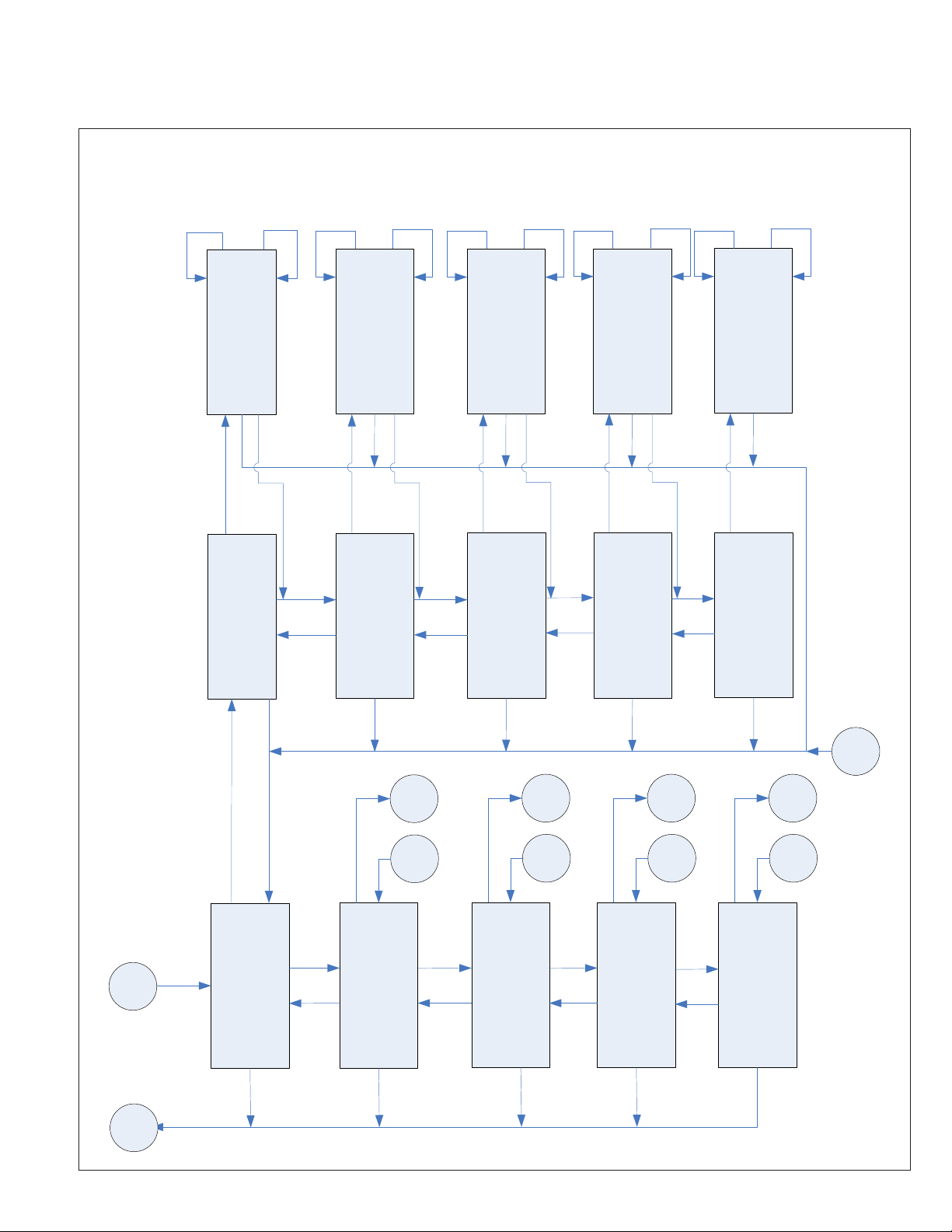
Time of Day
> Enter Hours: XX
or Start
Test Select
Start
Test Select
or Down Arrow
Enter Hours: XX
>Time of Day
Up Arrow
Time of Day
> Enter Minutes: XX
or Start
Cancel
Test Select
Start
Test Select
or Down Arrow
Enter Minutes: XX
>Time of Day
Up Arrow
Cancel
Date
> Enter Month: XX
or Start
Cancel
Test Select
Start
Test Select
or Down Arrow
Enter Month: XX
>Date
Up Arrow
Cancel
Date
> Enter Day of Month: XX
or Start
Cancel
Test Select
Start
Test Select
Enter Day of Month: XX
>Date
Up Arrow
Cancel
Date
> Enter Year: XXXX
or Start
Cancel or
Test Select
Start
or Down Arrow
Enter Year: XXXX
>Date
Cancel or
Test Select
JJ
BB
DD
FF
HH
Start
Cancel
Test Select
or Down Arrow
AA
Test Select
or Down Arrow
CC
Test Select
or Down Arrow
EE
Test Select
or Down Arrow
GG
B
System Settings
>Date & Time
Up Arrow
Cancel
System Settings
>Communications
Up Arrow
Cancel
System Settings
>Backup CFILE
Up Arrow
Cancel
System Settings
>Restore CFILE
Up Arrow
Cancel
System Settings
>Delete Log File
Cancel
C
EATON CORPORATION www.eaton.com
21
Page 22

Instruction Leaflet IL01906008E
Effective March 2011
Instructions for Testing Magnum DS
Digitrips with the MTK2000 Test Kit
Down Arrow (Change Value)
Start
Up Arrow (Change Value)
> 9600 | 19200 | 38400 | 57600 | 115200
Baudrate
>XXXXXX
or Start
Test Select
> 7 | 8 | 9
Down Arrow (Change Value)
Up Arrow (Change Value)
Databits
>X
or Start
Cancel
Test Select
Start
Down Arrow (Change Value)
Start
Up Arrow (Change Value)
> NONE | ODD | EVEN
Parity
>XXXX
or Start
Cancel
Test Select
> 1 | 2
Down Arrow (Change Value)
Up Arrow (Change Value)
Stopbits
>X
or Start
Cancel or
Test Select
Start
Test Select
Test Select
or Down Arrow
XXXXXX
>Baudrate
Up Arrow
X
>Databits
Cancel
Test Select
or Down Arrow
XXXX
Up Arrow
>Parity
Cancel
BB
or Down Arrow
X
Up Arrow
>Stopbits
Cancel or
Test Select
Start
AA
Cancel
22
EATON CORPORATION www.eaton.com
Page 23

Instructions for Testing Magnum DS
Digitrips with the MTK2000 Test Kit
Instruction Leaflet IL01906008E
Effective March 2011
<Complete/Failed>..
BACKUP CFILE
Process
Cancel
Test Select
Up & Down Arrow
Start
BACKUP CFILE
>Press Start To Begin
DD
Start
Test Select
Cancel
FF
Start
<Complete/Failed>..
RESTORE CFILE
Process
Cancel
Test Select
Up & Down Arrow
Start
RESTORE CFILE
>Press Start To Begin
Cancel
Test Select
HH
Start
<Complete/Failed>..
DELETE LOG FILE
Process
Cancel
Test Select
Up & Down Arrow
Start
DELETE LOG FILE
>Press Start To Begin
Cancel
Test Select
CC
EE
GG
JJ
EATON CORPORATION www.eaton.com
23
Page 24

Instruction Leaflet IL01906008E
Effective March 2011
This instruction leaflet is published solely for information purposes
and should not be considered all-inclusive. If further information is
required, you should consult an authorized Eaton sales representative.
The sale of the product shown in this literature is subject to the
terms and conditions outlined in appropriate Eaton selling policies
or other contractual agreement between the parties. This literature
is not intended to and does not enlarge or add to any such contract.
The sole source governing the rights and remedies of any purchaser
of this equipment is the contract between the purchaser and Eaton.
NO WARRANTIES, EXPRESSED OR IMPLIED, INCLUDING
WARRANTIES OF FITNESS FOR A PARTICULAR PURPOSE OR
MERCHANTABILITY, OR WARRANTIES ARISING FROM COURSE
OF DEALING OR USAGE OF TRADE, ARE MADE REGARDING
THE INFORMATION, RECOMMENDATIONS, AND DESCRIPTIONS
CONTAINED HEREIN.
In no event will Eaton be responsible to the purchaser or user in
contract, in tort (including negligence), strict liability or otherwise
for any special, indirect, incidental or consequential damage or loss
whatsoever, including but not limited to damage or loss of use of
equipment, plant or power system, cost of capital, loss of power,
additional expenses in the use of existing power facilities, or claims
against the purchaser or user by its customers resulting from the
use of the information, recommendations and description contained
herein.
Instructions for Testing Magnum DS
Digitrips with the MTK2000 Test Kit
Eaton Corporation
Electrical Sector
1111 Superior Ave.
Cleveland, OH 44114
United States
877-ETN-CARE (877-386-2273)
Eaton.com
© 2011 Eaton Corporation
All Rights Reserved
Printed in USA
Publication No. IL01906008E/ TBG000573
March 2011
Eaton is a registered trademark of Eaton
Corporation.
All other trademarks are property of their
respective owners.
 Loading...