

Eaton MPS12-30 Installation And Operation Manual
MPS12-30
Micro Power Solutions
Installation and Operation
Guide
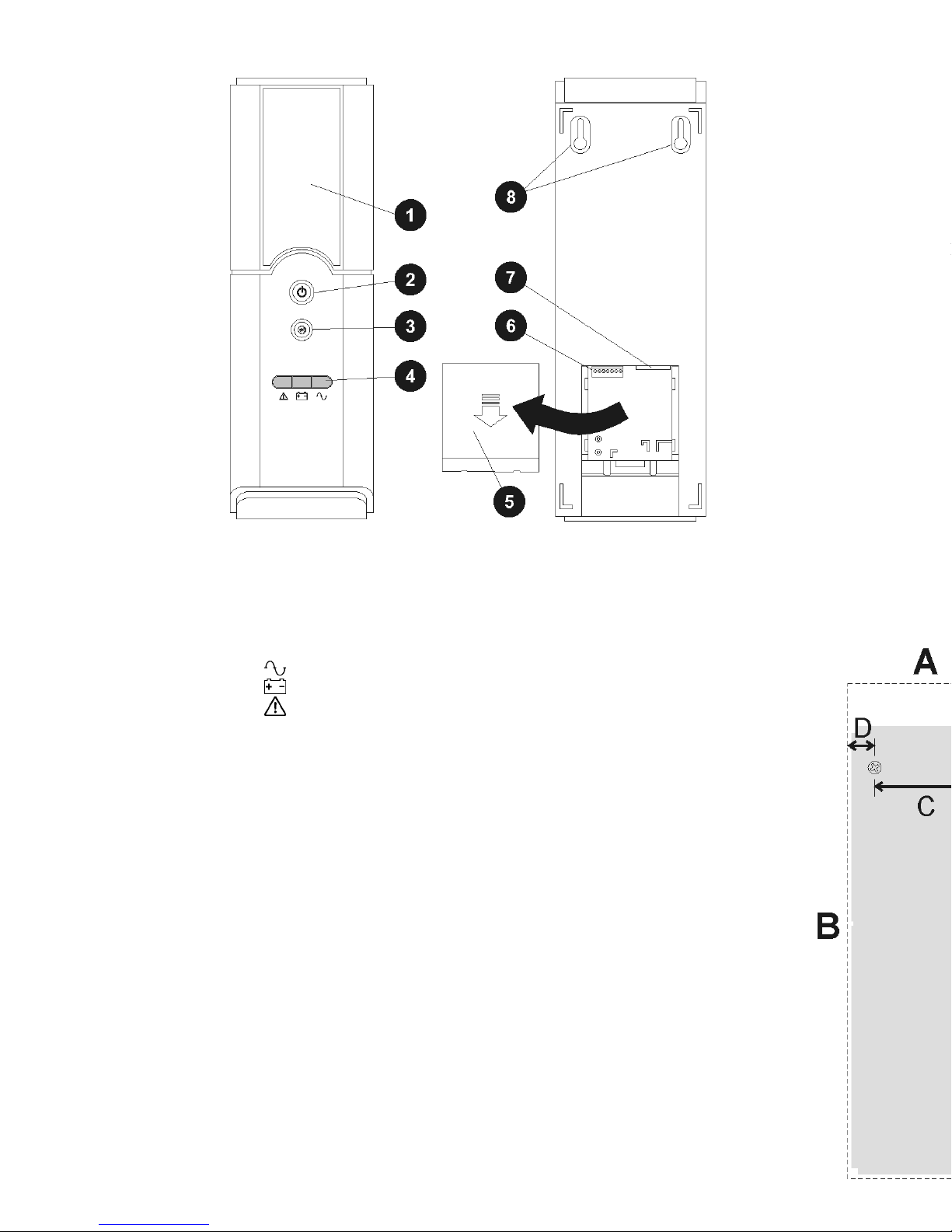
Front and Rear View
Battery cover
AC power switch (push to
switch on and off).
Alarm mute switch (push to
switch off the alarm sounds).
Indicator lights:
AC on – green
Battery mode – yellow
Fault - red
Connection cover
DC output and alarm
connector:
Pin 1: +12V dc output
Pin 2: 0V dc output
Pin 3: Alarm signal return
Pin 4: On battery
Pin 5: Replace battery
Pin 6: Battery missing
Pin 7: Low battery
AC power connector
Wall mount screw key-holes
Warnings
• If MPS12-30 is hotter than usual, or the battery is hot or
swollen, disconnect from AC socket/outlet, switch off AC
power switch (
), and contact your MPS12-30 supplier.
• Risk of explosion if incorrect battery type is used.
• Risk of internal damage if battery connections are reversed.
• Recycle old batteries according to local regulations. Or
contact your MPS12-30 supplier for advice.
What is supplied with the MPS12-30
• Installation and Operation Guide
• AC power cord
What you will need to install the MPS12-30
• 12V dc output/alarm cables (supplied with the terminal
equipment or see Specifications).
• Small, flat blade screwdriver for output and alarm
connectors.
• Optional: screwdriver and screws for wall mounting.
How to connect the MPS12-30
1. Unpack and check the MPS12-30.
If any item is damaged or missing contact the product supplier. Do
not use the MPS12-30 if it is damaged.
2. Remove the rear cover (
).
3. Connect the dc output wires to pin 1 (+) and pin 2 (-) (
The alarm connections are optional. Refer to instructions with the
terminal equipment.
4. Connect the AC power cord to the MPS12-30 (
5. Replace the rear cover.
How to mount the MPS12-30
1. Select a suitable location for the MPS12-30:
• Close to an AC power socket/outlet. The AC power cord is
the main AC disconnect device so ensure the socket/outlet
is easily accessible.
• Close to the terminal equipment. Check the length of the 12V dc
output/alarm cable.
• Protected from excessive moisture and temperature. See
Specifications (on next page) for the recommended temperature
range.
2. Either:
• Mount the MPS12-30 on its back on a flat, firm surface, or
• Mount it on a wall with two screws (see below). If needed,
use wall anchors or plugs to suit the type of wall and the
weight of the MPS12-30.
Minimum wall space
required:
A = 130mm, B = 420mm
Screw spacing:
C = 80mm
Place the screws at least:
• 25mm from any side
obstruction (D).
• 70mm below any
obstruction (E).
• 350mm above any
obstruction (F).

How to connect the MPS12-30
1. Unpack and check the MPS12-30.
If any item is damaged or missing contact the product supplier. Do
not use the MPS12-30 if it is damaged.
2. Remove the rear cover (
).
3. Connect the dc output wires to pin 1 (+) and pin 2 (-) (
).
The alarm connections are optional. Refer to instructions with the
terminal equipment.
4. Connect the AC power cord to the MPS12-30 (
).
5. Replace the rear cover.
How to mount the MPS12-30
1. Select a suitable location for the MPS12-30:
• Close to an AC power socket/outlet. The AC power cord is
the main AC disconnect device so ensure the socket/outlet
is easily accessible.
• Close to the terminal equipment. Check the length of the 12V dc
output/alarm cable.
• Protected from excessive moisture and temperature. See
Specifications (on next page) for the recommended temperature
range.
2. Either:
• Mount the MPS12-30 on its back on a flat, firm surface, or
• Mount it on a wall with two screws (see below). If needed,
use wall anchors or plugs to suit the type of wall and the
weight of the MPS12-30.
Minimum wall space
required:
A = 130mm, B = 420mm
Screw spacing:
C = 80mm
Place the screws at least:
• 25mm from any side
obstruction (D).
• 70mm below any
obstruction (E).
• 350mm above any
obstruction (F).
How to turn on the MPS12-30
1. Plug the MPS12-30 into the wall socket and switch on the
socket. MPS12-30 will beep briefly.
2. Push in the AC power switch (
two seconds.
3. The AC On light (green
MPS12-30 is performing a battery self-test).
4. Check the Alarm mute switch (
If the Alarm mute switch is pressed in, then the alarm will not sound
to alert you to a problem (the lights will still operate).
5. Check the connected equipment is operating correctly.
6. After five minutes, check the AC On light (green ) has
stopped flashing and no other lights are on.
If any other lights are on, or if the MPS12-30 beeps see below.
What the lights and alarm sounds mean
Light and Alarm
Sound*
No lights on AC power is not connected.
Green light on
Green light flashing
Yellow light on
and beeps every 5
seconds*
Yellow light
flashing
and beeps every
second*
Red light flashing
and beeps every 2
seconds*
Red light on
and beep is
continuous*
* No sound if the Alarm Mute switch (
** Typically battery will last for five hours, depending on battery age and
the connected equipment.
 Loading...