

Eaton Motor Insight C441 Product Installation Leaflet
Installation Leafl et IL04209007E-HVR
Supersedes March 2011
C441 Motor Insight™ Overload Relay (120V
Control Powered) Product Installation Leafl et
Effective May 2011
DANGER
HAZARDOUS VOLTAGE CAN CAUSE ELECTRIC SHOCK AND
BURNS. TO AVOID SHOCK HAZARD, DISCONNECT ALL POWER
BEFORE ANY WORK IS PERFORMED ON THIS DEVICE. FAILURE
TO DO SO WILL RESULT IN PERSONAL INJURY, DEATH OR
SUBSTANTIAL PROPERTY DAMAGE
AVERTISSEMENT
UNE TENSION ÉLECTRIQUE DANGEREUSE PEUT CAUSER DES
CHOCS ÉLECTRIQUES ET DES BRÛLURES. POUR ÉVITER DES
CHOCS ÉLECTRIQUES, DÉBRANCHER L’ALIMENTATION AVANT
D’Y EFFECTUER DU TRAVAIL. L’INOBSERVATION DE CES
INSTRUCTIONS ENTRAÎNERA DES BLESSURES CORPORELLES
GRAVES, LA MORT OU DES DÉGÂTS MATÉRIELS SUBSTANTIELS.
Voltage Ratings
Motor Insight overload relay is powered by 120V control
power between X1 - X2. This voltage range for the various models is given in the following table.
Table 1. Voltage Range
Nominal Rating Catalog
Number
CONTROL POWER
INPUT
C441P3309NOUI-HVR
C441059ONOUI-HVR
110 - 120V
Line Voltage C441P3309NOUI-HVR
C441059ONOUI-HVR
Wiring
Pass motor leads through Motor Insight overload relay
CT pass through. If multiple passes of the motor leads
are required, make sure that the current flow is from
top to bottom through Motor Insight overload relay. If
external CTs are used, pass the 5 amp secondary of the
external CTs through Motor Insight overload relay internal CTs. See Table 3A for wrap and CT multiplier.
Voltage
110 - 120 Vac;
(50/60 Hz)
+10% - 15%
0 - 1200Vac
0.20
3.31 (84.1)
(5.1)
4 Places
3.90
(99.1)
3.50
(88.9)
3.90 (99.1)
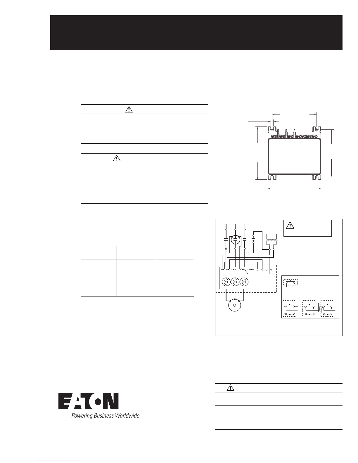
Figure 1. Mount with 10-32 Hardware Torque to 25
in-lb.
1 / L1 3 / L2 5 / L3
A1 A2
M
2/T1 4/T2
L X1 N X2 95 96 97 98 X1 X2 R1 R2
T2
T1
3 PHASE
AC MOTOR
NOTE:
X1, X2 - 120V Control Power Input.
R1, R2 - 120V RESET INPUT
2/13
3/14
6/T3
T3
CPT
120V
ATTENTION
CONTROL CIRCUITS ARE B300 RATED USE A
CPT AND SEPRATATE CONTROL WHEN LINE
VOLTAGE IS ABOVE 240VAC.
REMOTE PILOT DEVICES
2 WIRE CONTROL
NOT FOR USE
WITH AUTO RESET
OL RELAYS.
3 WIRE CONTROL
START
STOP
3
1
WHEN MORE THAN ONE
PUSH BUTTON STATION IS
USED OMIT CONNECTOR
A AND CONNECT PER
SKETCH BELOW.
START
3
2
STOP
1
A
START
STOP
Figure 2. Typical Starter Application Sample Wiring
Diagram
Motor Insight overload relay is factory set for manual
reset operation. See Table 5 for automatic reset opera-
tion.
3
2
1
WARNING AVERTISSEMENT
AUTOMATIC RESET IS NOT INTENDED FOR TWO-WIRE CONTROL DEVICES.
CE DISPOSITIF DE REENCLENCHEMENT AUTOMATIQUE NE
CONVIENT PAS AUX COMMANDES À DEUX
CONDUCTEURS.

Installation Lea et IL04209007E-HVR
Effective May 2011
C441 Motor Insight™ Overload Relay (120V
Control Powered) Product Installation Leafl et
Terminal Connections
Motor Insight overload relay provides the following terminal connections. NC 95/96 contact is open when the device is unenergized.
USE 75°C CU WIRE ONLY
* No Motor Loads, 9A Max
120VAC Control Power 50/60 Hz
L
N
X1
X2
18-12 AWG Torque 0.6 Nm/5.3 lb-in.
B300 PILOT DUTY ONLY
NC NO CTRL PWR RESET
95 96 97 98 X1 X2 R1
120VAC
120VAC
120VAC
R2
Figure 3. Terminal Connection Diagram
Table 2. Terminal Connection Specifications
Name Designation Input Description
L1, L2
Control Power
L, N
Fault Relay 95/96 UL® 508
Programable
97/98 UL® 508
Auxiliary Relay*
Reset
Input
R1
R2
* See section 6.7 of Users Manual MN04209001E for instructions to configure the programmable auxiliary relay, which changes the behavior of the relay
from the default and allows for greater flexibility and alarming.
93.5 - 132Vac Voltage input
- X1*, X2*, = 120V
- Tie X1 to X1
- Tie X2 to X2
- Inputs should have short circuit
protection
- Terminal provided for wiring
control power transformer
(9A maximum capacity).
- 95/96 Contact opens when the unit
B300
is faulted or unpowered.
-97/98 Contact closes when the unit
B300
120 Vac
is faulted or unpowered.
Fault Reset Input.
+10%/-15%
CAUTION!
THE OPENING OF BRANCH-CIRCUIT PROTECTIVE DEVICE MAY BE AN INDICATION THAT A FAULT HAS BEEN INTERRUPTED. TO REDUCE THE RISK OF
FIRE OR ELECTRIC SHOCK, CURRENT-CARRYING PARTS AND OTHER COMPONENTS OF THE CONTROLLER SHOULD BE EXAMINED AND REPLACED
IF DAMAGED. IF BURNOUT OF THE ELEMENT OF AN OVERLOAD RELAY
OCCURS, THE COMPLETE OVERLOAD RELAY SHOULD BE REPLACED.
ATTENTION
LE DÉCLENCHEMENT DU DISPOSITIF DE PROTECTION DES DÉRIVATIONS
PEUT SIGNIFIER QU’UN COURANT DE DÉFAUT A ÉTÉ INTERROMPU. POUR
RÉDUIRE LE RISQUE D’INCENDIE OU DE CHOC ÉLECTRIQUE, LES PIÈCES
PORTEUSES DE COURANT ET LES AUTRES COMPOSANTS DE LA COMMANDE DOIVENT ÊTRE VÉRIFIÉS ET REMPLACÉS S’ILS SONT ENDOMMAGÉS. SI L’ÉLÉMENT PORTEUR DE COURANT DU RELAIS DE SURCHARGE
GRILLE, LE RELAIS DE SURCHARGE ENTIER DOIT ÊTRE REMPLACÉ.
Initial Configuration
On initial power-up, Motor Insight overload relay displays a “rOF”
message. This indicates that the fault relay is OFF. Configure the
device for the application prior to resetting the device.
To turn the fault relay OFF, press the Trip button.
Programming Set Points
Motor Insight overload relay is easy to configure. Viewing and
editing protection set points can be performed in the Protection
and Operation Mode. The following steps outline the procedure
for modifying any of the set points.
Step 1: Press Mode button until Protection or Operation
Mode Led is lit.
Mode
Step 2: Press Up or Down button until the desired O/P LED
is lit. Display shows the current parameter value.
110
Step 3: Press the Edit/Save button. The display now shows
the parameter value but is now flashing.
Edit/Save
Step 4: Use the Up/Down button to adjust the parameter
to the desired value.
Step 5: Press the Edit/Save button. The Display now shows
the new parameter value that has been saved by the device.
Edit/Save
110
120
120
Configuring the Thermal Overload Protection Feature
Motor Insight overload relay features electronic motor overload protection. This feature protects the motor and power wiring against
overheating caused by excessive current for extended periods
of time.
The trip current is programmed by entering the motor full load
amperes (FLA) using the Motor FLA parameter. The trip class
(5 to 30) is set using the Trip Class parameter.
The FLA range of the overload relay can be modified with the use
of multiple turns through the CTs or with the use of external CTs.
Use the following tables to appropriately configure the device for the
application. If the application requires the FLA range to be extended,
program the CT multiplier first.
Table 3A. FLA Range
Current
Range
Catalog
Number
Motor
FLA
.33 – 9 C441P3309NOUI-HVR .33 - 1.5
.4 - 1.8
.5 - 2.25
.67 - 3.0
1 – 5
2 – 9
60 – 135
120 – 270
240 – 540
5 – 90 C441059ONOUI-HVRI 5 – 22.5
6.67 – 30
10 – 45
20 – 90
Conductors
Through CT
6
5
4
3
2
1
1
1
1
4
3
2
1
CT
Multiplier
6
5
4
3
2
1
150 - (150:5)
300 - (300:5)
600 - (600:5)
4
3
2
1
Important Note: After an overload trip, Motor Insight relay cannot be reset
until the thermal model decays to a thermal capacity that is thermally safe for
a motor restart. Cycling the power does not reset the thermal model.
Table 3B. Service Factor FLA Setting
Number of
Service Factor Motor FLA Setting
>1.15 Enter the motor nameplate FLA
=1.10 Enter the FLA as (1.1* nameplate FLA/1.15)
2
EATON CORPORATION www.eaton.com
 Loading...