

Eaton COOPER POWER SERIES, MN285018EN Installation And Operation Instructions Manual
COOPER POWER
SERIES
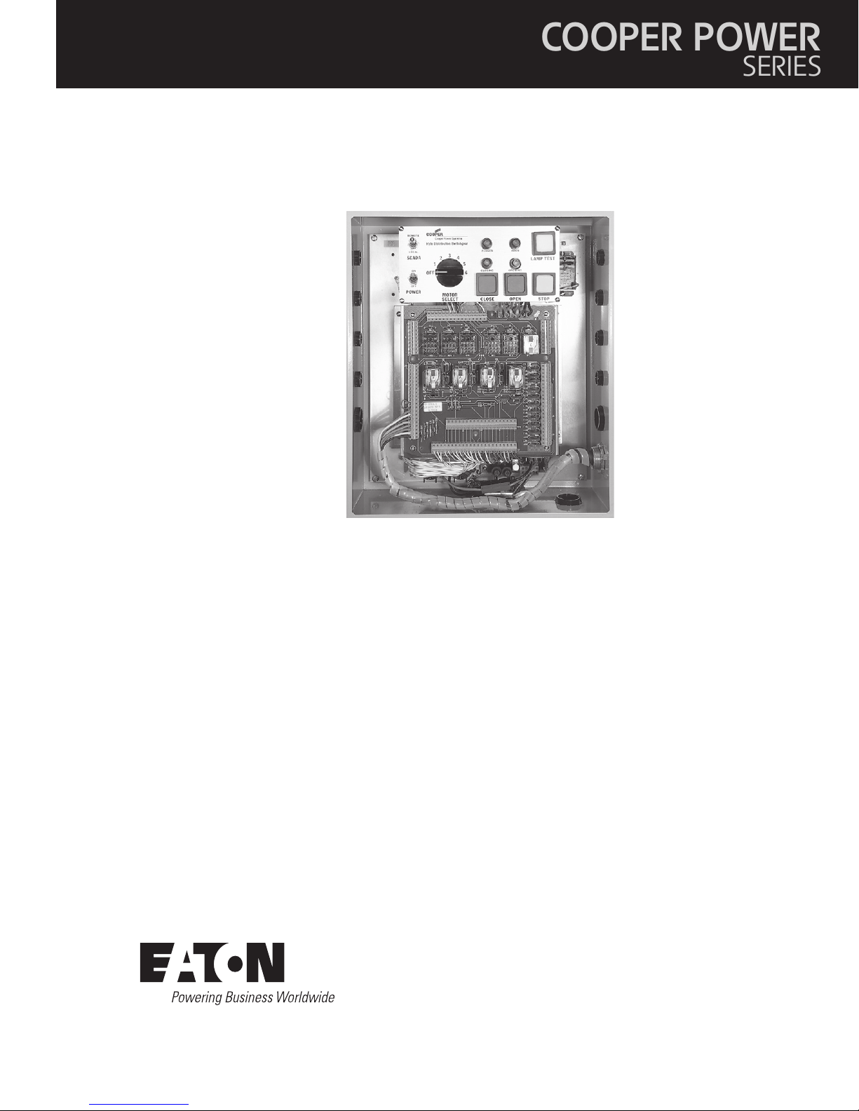
Padmounted Switchgear
MN285018EN
Effective May 2017
Supersedes October 1994 (S285-80-1)
DC motor operator control installation and operation instructions

DISCLAIMER OF WARRANTIES AND LIMITATION OF LIABILITY
The information, recommendations, descriptions and safety notations in this document are based on Eaton Corporation’s
(“Eaton”) experience and judgment and may not cover all contingencies. If further information is required, an Eaton sales
office should be consulted. Sale of the product shown in this literature is subject to the terms and conditions outlined in
appropriate Eaton selling policies or other contractual agreement between Eaton and the purchaser.
THERE ARE NO UNDERSTANDINGS, AGREEMENTS, WARRANTIES, EXPRESSED OR IMPLIED, INCLUDING WARRANTIES
OF FITNESS FOR A PARTICULAR PURPOSE OR MERCHANTABILITY, OTHER THAN THOSE SPECIFICALLY SET OUT IN ANY
EXISTING CONTRACT BETWEEN THE PARTIES. ANY SUCH CONTRACT STATES THE ENTIRE OBLIGATION OF EATON. THE
CONTENTS OF THIS DOCUMENT SHALL NOT BECOME PART OF OR MODIFY ANY CONTRACT BETWEEN THE PARTIES.
In no event will Eaton be responsible to the purchaser or user in contract, in tort (including negligence), strict liability or
other-wise for any special, indirect, incidental or consequential damage or loss whatsoever, including but not limited to
damage or loss of use of equipment, plant or power system, cost of capital, loss of power, additional expenses in the use of
existing power facilities, or claims against the purchaser or user by its customers resulting from the use of the information,
recommendations and descriptions contained herein. The information contained in this manual is subject to change
without notice.
OPERATION INSTRUCTIONS MN285018EN May 2017
i

Contents
DISCLAIMER OF WARRANTIES AND LIMITATION OF LIABILITY ....................................I
SAFETY FOR LIFE .........................................................................III
SAFETY INFORMATION ....................................................................III
Hazard statements ............................................................................. iii
Safety instructions .............................................................................. iii
PRODUCT INFORMATION ................................................................... 1
Introduction ....................................................................................1
Additional information . . . . . . . . . . . . . . . . . . . . . . . . . . . . . . . . . . . . . . . . . . . . . . . . . . . . . . . . . . . . . . . . . . . . . . . . . . . .1
Acceptance and initial inspection ...................................................................1
Handling and storage .............................................................................1
ISO Standards ..................................................................................1
Control battery storage and charging ................................................................1
Control power ..................................................................................2
DESCRIPTION OF CONTROL .................................................................2
Control operation ...............................................................................2
Auxiliary contacts ...............................................................................2
Simultaneous indication for SCADA .................................................................2
Electrical interlocks ..............................................................................2
Control operation-LOCAL Mode ................................................................... 3
LOCAL Mode operation ......................................................................... 3
LOCAL Mode features .......................................................................... 3
Battery charger board ........................................................................... 3
Wiring schematic .............................................................................. 4
Instructions for LOCAL Mode operation ............................................................ 6
SCADA Operation .............................................................................. 6
REMOTE Mode features ........................................................................ 6
Extended control accessory ...................................................................... 7
Extended control accessory operation .............................................................. 7
Outline diagram ............................................................................... 8
SCADA Terminal block connection procedures . . . . . . . . . . . . . . . . . . . . . . . . . . . . . . . . . . . . . . . . . . . . . . . . . . . . . . . . 9
DC Motor actuator ............................................................................. 9
TESTING PROCEDURES ................................................................... 9
Battery test ................................................................................... 9
Lamp test .................................................................................... 9
MAINTENANCE INFORMATION ............................................................ 10
Maintenance program ......................................................................... 10
Replacement parts ............................................................................ 10
ii
OPERATION INSTRUCTIONS MN285018EN May 2017
SAFETY
FOR LIFE
FOR LIFE
!
SAFETY
!
Safety for life
Eaton’s Cooper Power series products meet or exceed all applicable industry standards relating to product safety. We
actively promote safe practices in the use and maintenance of our products through our service literature, instructional
training programs, and the continuous efforts of all Eaton employees involved in product design, manufacture, marketing,
and service.
We strongly urge that you always follow all locally approved safety procedures and safety instructions when working around
high voltage lines and equipment, and support our “Safety For Life” mission.
Safety information
The instructions in this manual are not intended as a
substitute for proper training or adequate experience in the
safe operation of the equipment described. Only competent
technicians who are familiar with this equipment should
install, operate, and service it.
A competent technician has these qualifications:
• Is thoroughly familiar with these instructions.
• Is trained in industry-accepted high and low-voltage safe
operating practices and procedures.
• Is trained and authorized to energize, de-energize, clear,
and ground power distribution equipment.
• Is trained in the care and use of protective equipment
such as arc flash clothing, safety glasses, face shield, hard
hat, rubber gloves, clampstick, hotstick, etc.
Following is important safety information. For safe
installation and operation of this equipment, be sure to read
and understand all cautions and warnings.
Hazard Statement Definitions
This manual may contain four types of hazard statements:
DANGER
Indicates an imminently hazardous situation which,
ifnot avoided, will result in death or serious injury.
WARNING
Indicates a potentially hazardous situation which, if not
avoided, could result in death or serious injury.
CAUTION
Indicates a potentially hazardous situation which, if not
avoided, may result in minor or moderate injury.
CAUTION
Indicates a potentially hazardous situation which, if not
avoided, may result in equipment damage only.
Safety instructions
Following are general caution and warning statements that
apply to this equipment. Additional statements, relatedto
specific tasks and procedures, are located throughout
themanual.
DANGER
Hazardous voltage. Contact with hazardous voltage will
cause death or severe personal injury. Follow all locally
approved safety procedures when working around
high- and low-voltage lines and equipment. G103.3
WARNING
Before installing, operating, maintaining, or testing this
equipment, carefully read and understand the contents
of this manual. Improper operation, handling or
maintenance can result in death, severe personal injury,
and equipment damage. G101.0
WARNING
This equipment is not intended to protect human
life. Follow all locally approved procedures and safety
practices when installing or operating this equipment.
Failure to comply can result in death, severe personal
injury and equipment damage. G102.1
WARNING
Power distribution and transmission equipment must
be properly selected for the intended application. It
must be installed and serviced by competent personnel
who have been trained and understand proper safety
procedures. These instructions are written for such
personnel and are not a substitute for adequate training
and experience in safety procedures. Failure to properly
select, install or maintain power distribution and
transmission equipment can result in death, severe
personal injury, and equipment damage. G122.3
OPERATION INSTRUCTIONS MN285018EN May 2017
iii

Product information
THI
R8 R9
V1
V2
RY1
P1
1
F1
F2
D3
P2
TEST
BATTERY
B-
B+
DC motor operator control installation and operation instructions
Introduction
Service Information MN285018EN provides installation and
operating instructions for Eaton’s Cooper Power series DC
Motor Operator control. Before installing and operating this
control, carefully read and understand the contents of this
manual.
Additional information
These instructions do not claim to cover all details or
variations in the equipment, procedures, or process
described, nor to provide directions for meeting every
possible contin gency during installation, operation, or
maintenance. When additional information is desired to
satisfy a problem not cov ered sufficiently for the user’s
purpose, contact your Eaton representative.
Acceptance and initial inspection
Each Motor Operator control is completely assembled,
tested, and inspected at the factory. It is carefully calibrated,
adjusted and in good condition when accepted by the carrier
for shipment.
Upon receipt, inspect the equipment for signs of damage.
Inspect the control thoroughly for damage incurred during
shipment. If damage is discovered, file a claim with the
carrier immediately.
Handling and storage
Be careful during handling and storage of the control to
minimize the possibility of damage. If the control is to be
stored for any length of time prior to installation, provide a
clean, dry storage area. If storage is in a humid atmosphere,
make provisions to keep the control circuitry energized.
Ensure that the battery is disconnected during storage.
Quality standards
ISO 9001 Certified Quality Management System.
Control battery storage and charging
The 24 Vdc control battery is fully charged prior to
shipment and is ready for use. The 2.5 amp-hour sealed
lead acid jell-cell battery supplies the energy to activate the
motors and the control functions. The battery is capable of
running a motor for up to 25 open and 25 close operations
before recharge.
The 24 Vdc battery is charged by the temperature/voltage
regulated battery charger. The charger will provide an
ideal charge voltage based on the ambient temperature.
The battery charger will charge at a rate of 0 to 0.3 amps,
depending on battery voltage, and will return the battery from
low charge to full charge in 24 hours. Nominal battery life is
approximately six years.
If the battery is removed from the control for long term
storage, or if spare batteries require charging prior to
being put into service, a plug-in, bench-type, 2.5 amp-hour
battery charger is available, identified by the following
catalog number:
KME4-85-3 (120 Vac)
ote:N When shipped from the factory, the battery is
disconnected. Connect the battery plug into the
mating connector to complete the battery circuit.
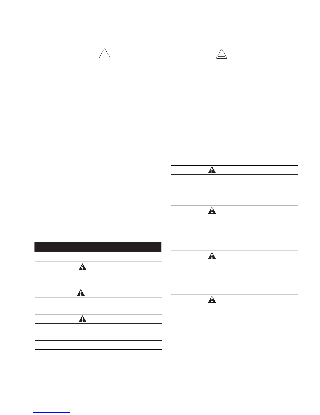
Battery
Figure 1. Outline diagram of AC supply and battery charger board
DC Battery Disconnect
AC Indicator light
Source #1 Fuse
Battery Test
Source #2 Fuse
Ground
OPERATION INSTRUCTIONS MN285018EN May 2017
Neutral #1
Neutral #2
Source #1
Source #2
1
 Loading...