

Eaton COOPER POWER Series, MN202002EN Installation, Operation, And Maintenance Instructions And Parts Replacement Information
COOPER POWER
SERIES
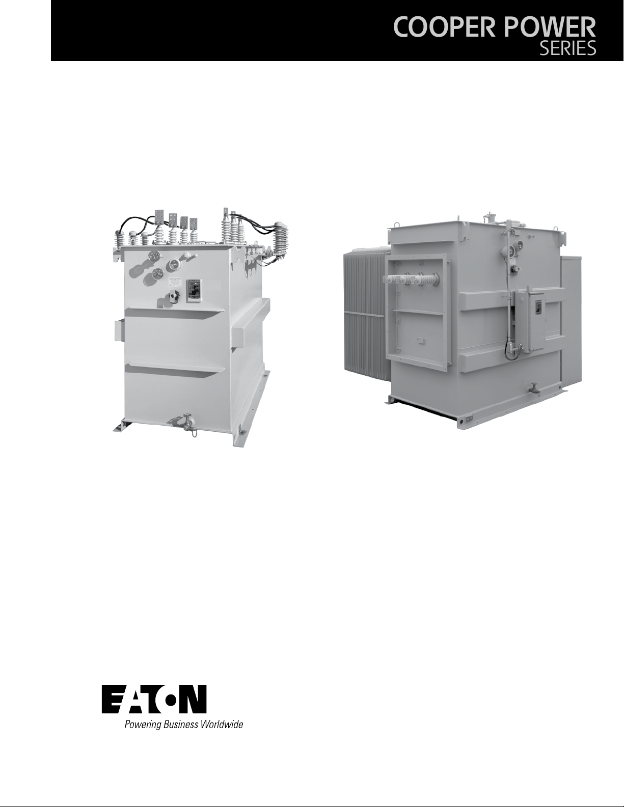
Substation
Transformers
MN202002EN
Effective June 2016
Supersedes S210-15-10 February 2013
Substation transformer installation, operation, and maintenance
instructions and parts replacement information

DISCLAIMER OF WARRANTIES AND LIMITATION OF LIABILITY
The information, recommendations, descriptions and safety notations in this document are based on Eaton Corporation’s
(“Eaton”) experience and judgment and may not cover all contingencies. If further information is required, an Eaton sales
office should be consulted. Sale of the product shown in this literature is subject to the terms and conditions outlined in
appropriate Eaton selling policies or other contractual agreement between Eaton and the purchaser.
THERE ARE NO UNDERSTANDINGS, AGREEMENTS, WARRANTIES, EXPRESSED OR IMPLIED, INCLUDING WARRANTIES
OF FITNESS FOR A PARTICULAR PURPOSE OR MERCHANTABILITY, OTHER THAN THOSE SPECIFICALLY SET OUT IN ANY
EXISTING CONTRACT BETWEEN THE PARTIES. ANY SUCH CONTRACT STATES THE ENTIRE OBLIGATION OF EATON. THE
CONTENTS OF THIS DOCUMENT SHALL NOT BECOME PART OF OR MODIFY ANY CONTRACT BETWEEN THE PARTIES.
In no event will Eaton be responsible to the purchaser or user in contract, in tort (including negligence), strict liability or otherwise for any special, indirect, incidental or consequential damage or loss whatsoever, including but not limited to damage or
loss of use of equipment, plant or power system, cost of capital, loss of power, additional expenses in the use of existing
power facilities, or claims against the purchaser or user by its customers resulting from the use of the information, recommendations and descriptions contained herein. The information contained in this manual is subject to change without notice.
ii SubStation tranSformer inStallation and partS replacement information MN202002EN JUNE 2016

Contents
DISCLAIMER OF WARRANTIES AND LIMITATION OF LIABILITY ................................... II
SAFETY FOR LIFE .........................................................................IV
SAFETY INFORMATION ....................................................................IV
Safety instructions .............................................................................. iv
PRODUCT INFORMATION ................................................................... 1
Introduction ....................................................................................1
Acceptance and initial inspection ...................................................................1
Handling .......................................................................................1
Storage .......................................................................................1
Quality standards. . . . . . . . . . . . . . . . . . . . . . . . . . . . . . . . . . . . . . . . . . . . . . . . . . . . . . . . . . . . . . . . . . . . . . . . . . . . . . . .1
INSTALLATION ............................................................................ 2
Installation location ..............................................................................2
Connections ....................................................................................2
Final inspection .................................................................................2
ACCESSORIES ............................................................................ 4
Liquid level gauge ...............................................................................4
Liquid temperature gauge .........................................................................4
Pressure-vacuum gauge ..........................................................................5
Pressure relief device ............................................................................5
Winding temperature gauge .......................................................................6
Transformer cooling fans ..........................................................................6
High voltage bushings ............................................................................7
Low voltage bushings ............................................................................7
De-energized tap-changer .........................................................................8
Insulating liquid .................................................................................8
Vacuum fault interrupter (VFI) ......................................................................9
MAINTENANCE ...........................................................................11
Periodic inspection .............................................................................11
Removing and replacing bushings ..................................................................11
Removing and replacing draw lead type bushings .....................................................11
Removing and replacing fixed stud or spade type bushings ..............................................12
Cover removal .................................................................................13
Insulating liquid maintenance .....................................................................14
APPLICABLE STANDARDS ................................................................. 14
R-TEMP FLUID-FILLED TRANSFORMERS ..................................................... 14
Dielectric strength ..............................................................................14
PEAK™ AND ENVIROTEMP™ FR3™ FLUID-FILLED TRANSFORMERS ............................. 15
Spare parts and service ..........................................................................15
PREVENTATIVE MAINTENANCE INSTRUCTIONS .............................................. 16
iiiSubStation tranSformer inStallation and partS replacement information MN202002EN JUNE 2016
!
SAFETY
FOR LIFE
Eaton meets or exceeds all applicable industry standards relating to product safety in its Cooper Power™ series products.
We actively promote safe practices in the use and maintenance of our products through our service literature, instructional
training programs, and the continuous efforts of all Eaton employees involved in product design, manufacture, marketing,
and service.
We strongly urge that you always follow all locally approved safety procedures and safety instructions when working around
high voltage lines and equipment, and support our “Safety For Life” mission.
Safety for life
!
SAFETY
FOR LIFE
Safety information
The instructions in this manual are not intended as a
substitute for proper training or adequate experience in the
safe operation of the equipment described. Only competent
technicians who are familiar with this equipment should
install, operate, and service it.
A competent technician has these qualifications:
• Is thoroughly familiar with these instructions.
• Is trained in industry-accepted high and low-voltage safe
operating practices and procedures.
• Is trained and authorized to energize, de-energize, clear,
and ground power distribution equipment.
• Is trained in the care and use of protective equipment
such as arc flash clothing, safety glasses, face shield, hard
hat, rubber gloves, clampstick, hotstick, etc.
Following is important safety information. For safe installation and operation of this equipment, be sure to read and
understand all cautions and warnings.
Hazard Statement Definitions
This manual may contain four types of hazard statements:
DANGER
Indicates an imminently hazardous situation which, if
not avoided, will result in death or serious injury.
WARNING
Indicates a potentially hazardous situation which, if not
avoided, could result in death or serious injury.
CAUTION
Indicates a potentially hazardous situation which, if not
avoided, may result in minor or moderate injury.
CAUTION
Indicates a potentially hazardous situation which, if not
avoided, may result in equipment damage only.
Safety instructions
Following are general caution and warning statements that
apply to this equipment. Additional statements, related to
specific tasks and procedures, are located throughout the
manual.
DANGER
Hazardous voltage. Contact with hazardous voltage will
cause death or severe personal injury. Follow all locally
approved safety procedures when working around highand low-voltage lines and equipment.
G103.3
WARNING
Before installing, operating, maintaining, or testing this
equipment, carefully read and understand the contents
of this manual. Improper operation, handling or
maintenance can result in death, severe personal injury,
and equipment damage.
G101.0
WARNING
This equipment is not intended to protect human
life. Follow all locally approved procedures and safety
practices when installing or operating this equipment.
Failure to comply can result in death, severe personal
injury and equipment damage.
G102.1
WARNING
Power distribution and transmission equipment must
be properly selected for the intended application. It
must be installed and serviced by competent personnel
who have been trained and understand proper safety
procedures. These instructions are written for such
personnel and are not a substitute for adequate training
and experience in safety procedures. Failure to properly
select, install or maintain power distribution and
transmission equipment can result in death, severe
personal injury, and equipment damage.
G122.3
iv SubStation tranSformer inStallation and partS replacement information MN202002EN JUNE 2016
Product information
CAUTION
Do not Exceed Transformer Ratings. Transformers
should be operated only at the ratings specified on the
transformer nameplate. Prolonged overload operation
will measurably shorten the projected service life of a
mineral oil-filled transformer. Eaton’s Cooper Power™
series PEAK™ transformers may help to extend
insulation life and can be operated at higher capacities
than traditional units while still exceeding ANSI
standard insulation life.
Introduction
This manual has been prepared to assist competent technicians in the installation, operation and service of primary or
secondary unit- or open-type substation trans-formers.
Substation transformers are designed for installation on
three-phase systems. All units are constructed for in-door
or outdoor mounting on a concrete pad with high and low
voltage cables entering operating compartments through
enclosed sidewall mounted bushings (unit-type transformers) or through cover or sidewall mounted bushings (opentype transformers).
Although every effort has been made to anticipate normal
installation, operation and servicing problems, these instructions do not cover all possible variations in equipment or
application conditions. All possible installation, operation or
service contingencies are not discussed. If additional information is required, contact a factory representative.
It is important that personnel using these instructions
be fully acquainted with industry accepted high and low
voltage safe operating practices and procedures. These
instructions are not intended as a substitute for proper
training or adequate experience in the safe operation of the
equipment described.
®
2. Before unloading the transformer, make an inspection to
detect any signs of damage or mishandling. Locate any
accessory parts that may have been shipped separately.
3. If any damage is detected or shortages are noticed,
write a brief description on the freight bill. Normally, the
transformer is shipped FOB point of manufacture, and
it is the customer's responsibility to file a claim against
the carrier. If the transformer was shipped FOB destination, notify your factory representative. He or she will,
with the inspector's report, take the necessary steps to
file a claim against the carrier.
Handling
For unloading, lifting hooks are provided near the top of the
transformer tank. Cable pull angles should not be over 30°
from vertical. Otherwise, spreaders should be used to hold
the lifting cables apart to avoid any bending of the structure
or lifting hooks.
WARNING
Do not attempt to lift the transformer by placing a continuous loop of cable or chain around the unit or lifting
lugs. Improper handling can result in death, severe personal injury and equipment damage.
If the transformer cannot be lifted by crane, it may be
skidded or moved with rollers. When jacking a transformer
to insert rollers underneath it, insure that at least two jacks
are used and that two adjacent corners are raised simultaneously and evenly to avoid warping the base. Jacks may be
placed only at the corners of the transformer base.
Do not place jacks under cooler assemblies, valves, or sheet
metal parts. When using rollers, use as many as necessary
to distribute the weight uniformly. To pull, attach pulling eyes
to the holes in the base at either end of the transformer.
Do not attach pulling lines to moldings or other sheet metal
parts of the transformer.
Read this manual first
Read and understand the contents of this manual and follow
all locally approved procedures and safety practices before
installing or operating this equipment.
Additional information
These instructions cannot cover all details or variations in
the equipment, procedures, or process described, nor to
provide directions for meeting every possible contingency
during installation, operation, or maintenance. For additional
information, contact your Eaton representative.
Acceptance and initial inspection
It is important that a thorough inspection of the transformer
be made before it is unloaded from the carrier.
1. Ensure that all parts listed on the bill of lading are
present.
Storage
Whenever possible, the transformer should be stored at its
permanent location.
The insulating liquid should be at its proper level and the
gas space pressurized with dry nitrogen to approximately
two psig. Then it should be tightly sealed so that no
moisture or air can enter the tank. Periodic inspection
should determine that the pressure gauge does not remain
at zero, and proper liquid level is maintained at all times.
The transformer should not be stored in the presence of
corrosive gases (e.g., chlorine). Exterior surfaces of the transformer should be maintained against rust and corrosion.
Before placing a transformer into service after an ex-tended
storage time, check fans, alarm and control circuits, and the
dielectric strength of the insulating liquid.
Quality standards
ISO 9001 certified quality management system
1SubStation tranSformer inStallation and partS replacement information MN202002EN JUNE 2016
Installation
Installation location
The transformer should be located on a concrete pad of
sufficient strength to support the weight of the unit. The
pad must be level. The location of the transformer, whether
indoor or outdoor, should provide for adequate accessibility,
ventilation and ease of inspection. The transformer should
be at least 24 inches from any obstruction. These are
the recommendations of the manufacturer for operation
purposes; see your local codes for additional guidelines.
Location in areas of corrosive chemicals should be avoided.
These substation transformers are built to operate at
altitudes up to 3300 feet at 30°C average and 40°C
maximum ambient, unless otherwise specified. Before
operating a standard transformer at higher altitudes, contact
your factory representative.
Adequate ventilation must be provided. For indoor
installations, room air inlets should be located at floor level;
the air outlets should be located as high as the room will
permit. The number and size of the air inlets depends upon
the rating of the transformer. In general, about 20 square
feet each of inlet and outlet area should be provided for
each 1000 kVA of transformer capacity. If the ventilation
system is adjustable, it should be locked permanently open
to avoid overheating of the transformer in case of operator
error.
Connections
Connections must be made without placing undue stress
on the bushing terminals. Conductors should be securely
fastened in place and supported properly, with allowance
for expansion and contraction. Make sure that the tap
connection is proper for the required voltage. Changes in
tap connections must be done ONLY with the transformer
high voltage and low voltage circuits completely
"DE-ENERGIZED". Safely verify that there is no voltage
present at the terminals.
WARNING
Do not change connections on a transformer that is
energized. Ground all circuits before making any transformer connection. Failure to observe precautions when
making connections can result in exposure to high voltages, which can cause death, severe personal injury or
damage to the equipment.
WARNING
Do not make any connections, except as authorized by
the nameplate or schematic. Improper connections
can result in severe personal injury and damage to the
equipment.
Transformers equipped with an internal terminal board are
normally shipped with the higher voltage connected, unless
otherwise specified by the customer.
A secure and effective low resistance ground is essential
for protection. The transformer must be grounded permanently by connecting a heavy ground cable to the ground
pad located at the bottom of the tank. If the transformer is
designed for operation in a solidly grounded neutral system,
the neutral connection should be solidly and permanently
grounded with minimum resistance.
WARNING
Improper grounding may result in personal injury or
damage to the equipment.
Lightning arresters are recommended for every trans-former
installation. Arresters of proper rating should be located as
close as possible to the transformer terminations.
When alarm contacts or controls are supplied with the
transformer accessories, a connection box may be provided
to facilitate termination of the customer's cable or conduit.
Final inspection
The final inspection can be done in three major steps:
Electrical, Internal and External.
WARNING
Do not tamper with interlocks, alarm or control circuits.
Doing so can produce unsafe conditions for operators or
result in damage to the equipment.
Electrical inspection should determine that:
1. All external connections have been made properly
(phasing of connections to terminal bushings, etc.).
2. All connections are tight and secure.
3. All accessory contact circuits are operational.
4. Current transformer circuits, if supplied, have secondaries either shorted or connected through their load.
5. Tap changer is operative and properly positioned.
6. The correct transformer ratio exists for units furnished
with internal terminal board.
7. There is no grounding of windings that are not
intended to be grounded. A 1000-volt megger test is
recommended.
8. There is continuity in all windings.
9. The dielectric strength of the insulating liquid is
30 kV minimum when new. (Refer to section for
"Testing Insulating Liquid" in this manual.)
10. The neutral and ground connections have been properly
made.
2 SubStation tranSformer inStallation and partS replacement information MN202002EN JUNE 2016
If an internal inspection is required, assure that:
1. There is no evidence of moisture.
2. All available bolted connections are tight.
3. There has been no shifting of any parts or any other
damage.
The external inspection should determine that:
1. All scratches have been painted.
2. The bushings are clean.
3. The accessories are operative.
4. There are no tools, or other objects, left on top of the
transformer or inside any enclosure.
5. The liquid level is correct.
6. The transformer holds positive pressure.
7. The manhole covers are tightly bolted.
8. All protective covers are closed and bolted tight.
9. The mechanical pressure relief device is reset.
CAUTION
Whenever it is necessary to open a liquid-filled transformer, insure that the liquid temperature is higher
than the outside air temperature. Otherwise, internal
moisture condensation may occur, which could lead to
failure of the transformer.
CAUTION
Before breaking the seal of any handhole, manhole or
bushing hole, bleed internal pressure to zero. Seals
should not be broken in the presence of fog, rain or
snow, or if there is any evidence of condensation on the
transformer tank. If even a very slight amount of such
moisture enters the transformer tank, it can decrease
the dielectric strength of the cooling liquid to dangerously low levels, which can result in damage to the
equipment.
CAUTION
Only authorized personnel should be permitted on top
of the transformer and every precaution should be taken
to avoid dropping objects into the transformer. Workers
should not have anything in their pockets (such as pens,
pencils, coins, etc.) and their clothing should not have
loose metal buttons, badges, buckles, etc. Wristwatches
should also be removed. When dropped into the
transformer tank, such objects can cause equipment
malfunction and damage.
3SubStation tranSformer inStallation and partS replacement information MN202002EN JUNE 2016
Accessories
Liquid level gauge
Liquid temperature gauge
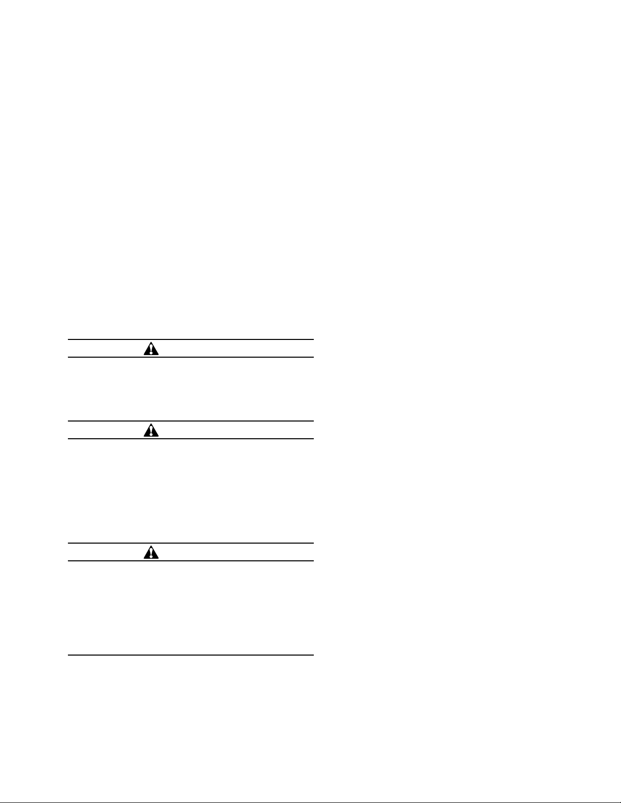
Figure 1. Liquid level gauge.
A liquid level indicator is provided to aid in the systematic
inspection of the transformer under load. It consists of
a float-arm inside the tank, an indicating pointer and a
magnetic coupling between the two across a liquid-tight
separation. Under normal operating conditions, the pointer
should be between the lo/min and hi/max level markings.
The gauge may be furnished with SPDT (Single Pole Double
Throw) alarm contacts to give a remote annunciation of
low liquid level. For contact wiring and terminal points,
see the accessory connection diagram furnished with the
transformer.
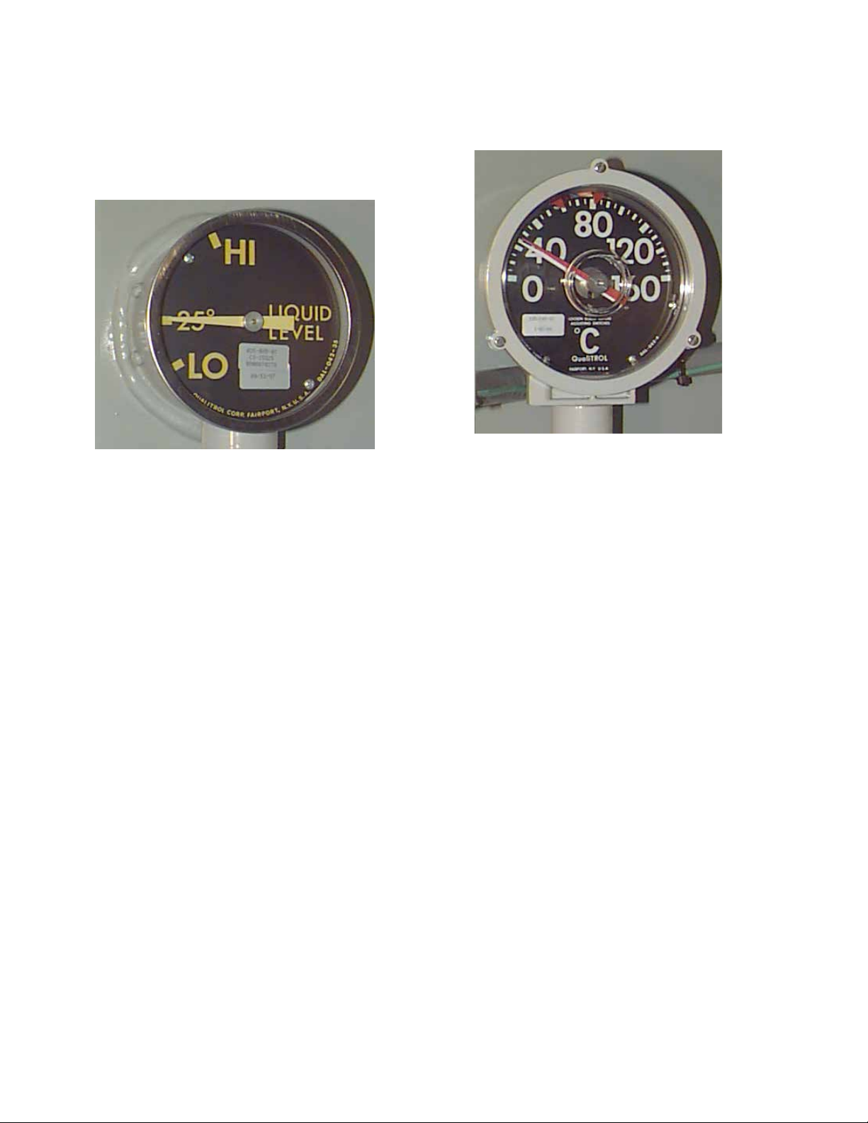
Figure 2. Liquid temperature gauge.
The temperature gauge is furnished to indicate the top
liquid temperature in the tank in degrees Centigrade. The
temperature-sensitive element is mounted in a leak-proof
well, permitting removal of the thermometer without lowering the oil level. The device is furnished with an additional
red pointer to show the highest temperature attained since
the last reset. To reset the maximum indicator, turn the knob
in the center of the dial.
The thermometer can be furnished with two SPDT contacts
for a high temperature alarm, for energizing a fan circuit or
for a low temperature alarm. The trip settings are indicated
by the red tick marks on the edges of the dial. For additional
wiring and contact settings, refer to the schematic furnished
with the transformer.
4 SubStation tranSformer inStallation and partS replacement information MN202002EN JUNE 2016
 Loading...