

Eaton MMX11AA1D7, MMX11AA2D4, MMX11AA3D7, MMX11AA2D8, MMX32 Operating Instructions Manual
...
Operating instructions
M-MaxTM Series
Adjustable Frequency Drive
04/10 MN04020001Z-EN
replaced 06/09 AWB8230-1603en

All brand and product names are trademarks or registered
trademarks of the owner concerned.
Emergency On Call Service
Please call your local representative:
http://www.eaton.com/moeller/aftersales
or
Hotline of the Moeller Field Service:
+49 (0) 180 5 223822 (de, en)
AfterSalesEGBonn@eaton.com
Original Operating Instructions.
The German-language edition of this document is the original
operating manual.
Translation of the original operating manual.
All editions of this document other than those in German language are translations of the original German manual.
1
st
edition 2009, edition date 06/09
2
nd
edition 2010, edition date 04/10
© 2009 by Eaton Industries GmbH, 53105 Bonn
Production: Thomas Kracht, Jutta Kremer
Translation: globaldocs GmbH
All rights reserved, including those of the translation.
No part of this manual may be reproduced in any form
(printed, photocopy, microfilm or any other process) or
processed, duplicated or distributed by means of
electronic systems without written permission of Eaton
Industries GmbH, Bonn.
Subject to alteration without notice.

Danger!
Dangerous electrical voltage!
Before commencing the installation
• Disconnect the power supply of the device.
• Ensure that devices cannot be accidentally restarted.
• Verify isolation from the supply.
• Earth and short circuit the device.
• Cover or enclose any adjacent live components.
• Follow the engineering instructions (IL04020001E) for the
device concerned.
• Only suitably qualified personnel in accordance with
EN 50110-1/-2 (VDE 0105 Part 100) may work on this
device/system.
• Before installation and before touching the device ensure
that you are free of electrostatic charge.
• The functional earth (FE, PES) must be connected to the
protective earth (PE) or the potential equalisation. The system
installer is responsible for implementing this connection.
• Connecting cables and signal lines should be installed so
that inductive or capacitive interference does not impair the
automation functions.
• Install automation devices and related operating elements in
such a way that they are well protected against unintentional
operation.
• Suitable safety hardware and software measures should be
implemented for the I/O interface so that an open circuit on the
signal side does not result in undefined states in the
automation devices.
• Ensure a reliable electrical isolation of the extra-low voltage of
the 24 V supply. Only use power supply units complying with
IEC 60364-4-41 (VDE 0100 Part 410) or HD384.4.41 S2.
• Deviations of the mains voltage from the rated value must
not exceed the tolerance limits given in the specifications,
otherwise this may cause malfunction and dangerous
operation.
• Emergency stop devices complying with IEC/EN 60204-1 must
be effective in all operating modes of the automation devices.
Unlatching the emergency-stop devices must not cause a
restart.
• Devices that are designed for mounting in housings or control
cabinets must only be operated and controlled after they have
been installed and with the housing closed. Desktop or
portable units must only be operated and controlled in
enclosed housings.
• Measures should be taken to ensure the proper restart of
programs interrupted after a voltage dip or failure. This should
not cause dangerous operating states even for a short time.
If necessary, emergency-stop devices should be implemented.
• Wherever faults in the automation system may cause injury or
material damage, external measures must be implemented to
ensure a safe operating state in the event of a fault or
malfunction (for example, by means of separate limit switches,
mechanical interlocks etc.).
• Depending on their degree of protection, adjustable frequency
drives may contain live bright metal parts, moving or rotating
components or hot surfaces during and immediately after
operation.
• Removal of the required covers, improper installation or
incorrect operation of motor or adjustable frequency drive may
cause the failure of the device and may lead to serious injury or
damage.
• The applicable national accident prevention and safety
regulations apply to all work carried on live adjustable
frequency drives.
• The electrical installation must be carried out in accordance
with the relevant regulations (e. g. with regard to cable cross
sections, fuses, PE).
• Transport, installation, commissioning and maintenance work
must be carried out only by qualified personnel (IEC 60364,
HD 384 and national occupational safety regulations).
• Installations containing adjustable frequency drives must be
provided with additional monitoring and protective devices in
accordance with the applicable safety regulations.
Modifications to the adjustable frequency drives using the
operating software are permitted.
Eaton Corp.
Safety instructions
I

• All covers and doors must be kept closed during operation.
• To reduce the hazards for people or equipment, the user must
include in the machine design measures that restrict the
consequences of a malfunction or failure of the drive
(increased motor speed or sudden standstill of motor).
These measures include:
– Other independent devices for monitoring safety-related
variables (speed, travel, end positions etc.).
– Electrical or non-electrical system-wide measures
(electrical or mechanical interlocks).
– Never touch live parts or cable connections of the adjustable
frequency drive after it has been disconnected from the
power supply. Due to the charge in the capacitors, these
parts may still be live after disconnection. Fit appropriate
warning signs.
II

04/10 MN04020001Z-EN
Contents
About This Manual 5
Notes on the second MMX upgrade 5
Writing conventions 6
Abbreviations and Symbols 7
– Mains supply voltages 7
–Units 7
1 M-MaxTM Series 9
System overview 9
Checking the Delivery 10
Rating data on the nameplate 11
– Key to part numbers 12
– General rated operational data 14
– Technical data 16
Description of the M-Max
Features 18
Selection criteria 20
Proper use 21
Maintenance and inspection 22
Storage 22
Charging DC link capacitors 22
Service and warranty 22
TM 18
2 Engineering 23
Introduction 23
Electrical power network 24
– Mains connection and configuration 24
– Mains voltage and frequency 24
– Voltage balance 24
– Idle power compensation devices 25
– Mains reactors 25
Safety and switching 26
– Fuses and cable cross-sections 26
– Cables and fuses 26
– Residual-current device (RCD) 26
– Mains contactor 27
EMC measures 27
Motor and Application 28
– Motor selection 28
– Connecting motors in parallel 28
– Motor and circuit type 29
– Bypass operation 30
– Connecting EX motors 30
3 Installation 31
Introduction 31
Installation instructions 31
– Mounting position 31
– Cooling measures 31
– Fixing 32
EMC installation 35
– EMC measures in the control panel 35
– Earthing 35
1
Contents
04/10 MN04020001Z-EN
– Screen earth kit 35
Electrical Installation 37
– Connection to power section 38
– Arrangement and connection of the power terminals 40
– Connection on control section 42
– Arrangement and connection of the control signal
terminals 43
– Microswitches and control signal terminals 43
– Function of the control signal terminals 44
–Block diagram 50
– Insulation testing 53
4Operation 55
Checklist for commissioning 55
Operational hazard warnings 56
Commissioning with control signal terminals (factory
setting) 57
– Brief Instructions 60
5 Error and Warning Messages 63
Introduction 63
– Error messages 63
– Acknowledge fault message (Reset) 63
– Fault log (FLT) 63
– Alarm messages 63
6 Parameters 67
Control unit 67
– Display unit 68
– General information on menu navigation 68
– Setting parameters 69
Parameter menu (PAR) 71
– Quickstart Wizard 72
– Parameter selection (P1) 73
– Analog input (P2) 75
– Digital input (P3) 78
– Analog output (P4) 83
– Digital output (P5) 84
– Drives control (P6) 88
– Motor (P7) 94
– Protective functions (P8) 95
– PID controller (P9) 100
– Fixed frequency setpoint value (P10) 104
– U/f-characteristic curve (P11) 111
– Braking (P12) 116
– Logic function (P13) 121
– Second parameter set (P14) 124
– System parameter 128
Operational data indicator (MON) 130
Setpoint input (REF) 132
2

04/10 MN04020001Z-EN
Contents
7 Serial interface (Modbus RTU) 135
General information about Modbus 135
Communications in a Modbus network 135
Modbus parameters 136
– Operating mode Modbus RTU 137
– Structure of the master request 138
– Data storage with Modbus 140
– Modbus-Register-Mapping 140
Modbus Process Data 141
– Explanation of function code 144
Appendix 147
Special technical data 147
– Device series MMX11 147
– Device series MMX12 148
– Device series MMX32 149
– Device series MMX34 150
Dimensions and frame size 151
MMX-COM-PC 153
– PC interface module 153
MMX-NET-XA 154
– Mounting frame for fieldbus connection 154
XMX-NET-CO-A 155
XMX-NET-PD-A, XMX-NET-PS-A 156
– PROFIBUS DP fieldbus interface card 156
Cables and fuses 157
Mains contactors 159
Radio interference suppression filters 161
– Special technical data for MMX-LZ... 163
Dimensions and sizes of the MMX-LZ... interference
suppression filters 164
Brake resistors 165
– Brake resistors BR1…-T-PF and BR3…-T-PF 166
– Brake resistors BR2… and BR2…-T-SAF 166
Mains chokes 169
Motor chokes 171
Sinusoidal filters 173
List of parameters 176
– Quick configuration (basis) 176
– All Parameters 179
Index 193
3

04/10 MN04020001Z-EN
4
04/10 MN04020001Z-EN
c
a
b
I
OK
BACK
RESET
LOC
REM
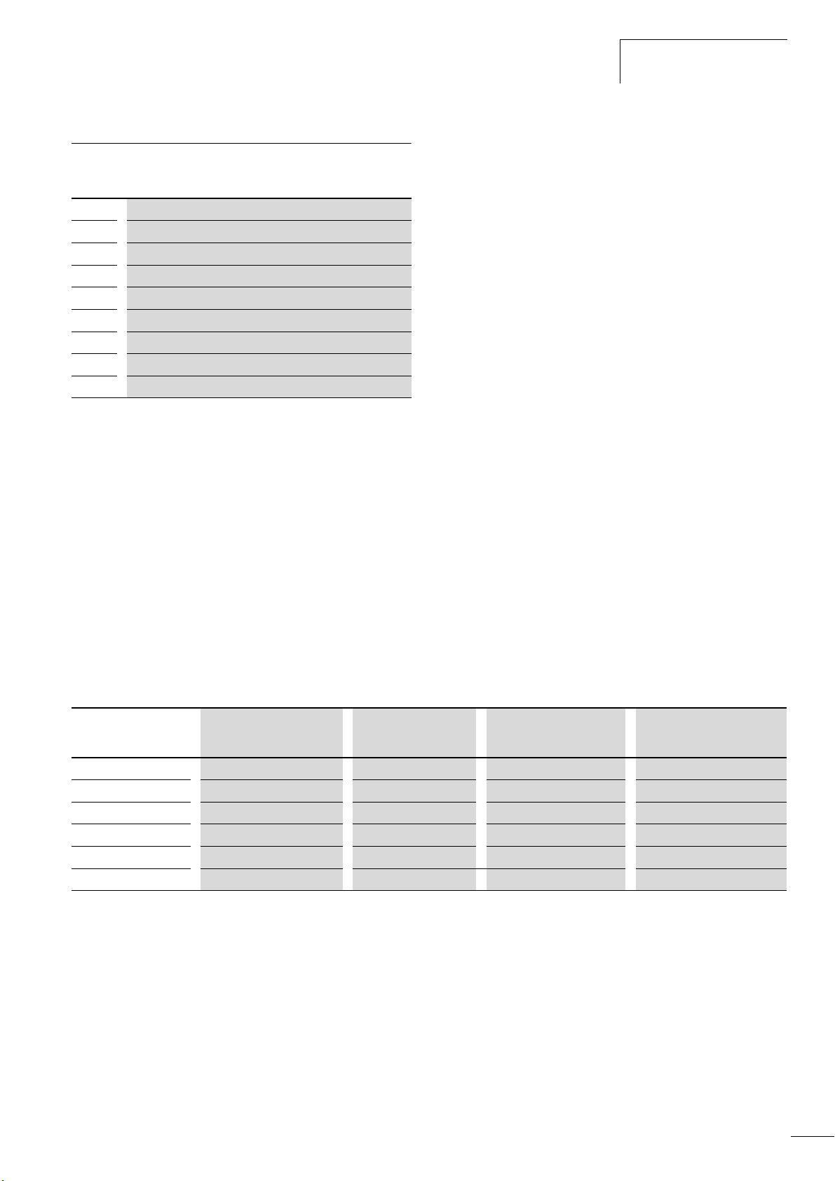
About This Manual
This manual provides a description of the frequency inverters of
TM
the M-Max
series. It provides special information required for
project planning, installation and for the operation of the MMX
frequency inverter. All information applies to the specified
hardware and software versions.
Please read the manual thoroughly before you install and operate
the frequency inverter.
We assume that you have a good knowledge of engineering
fundamentals and that you are familiar with handling electrical
systems and machines, as well as with reading technical drawings.
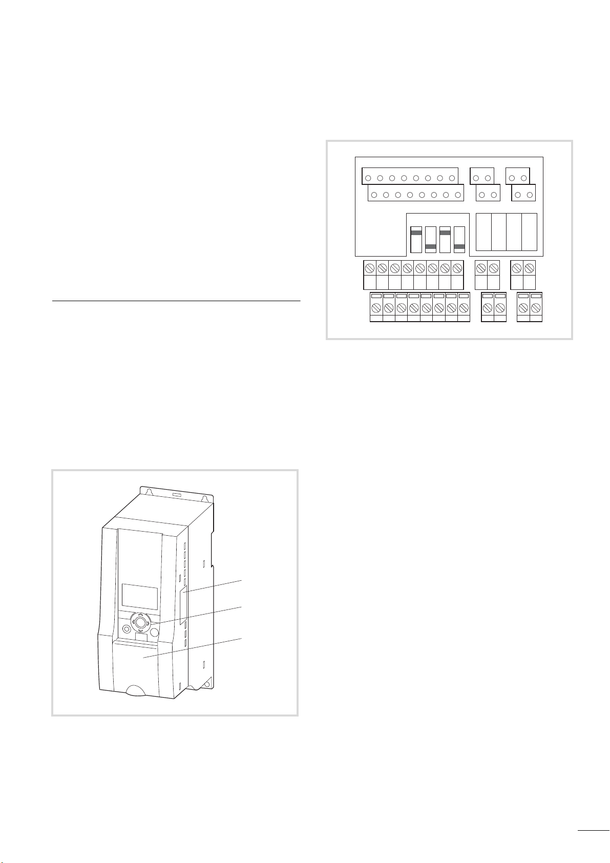
Notes on the second MMX upgrade
This second edition of the manual describes the extended functionality of the MMX. This applies to frequency inverters of the
TM
M-Max
series from production date 12W10 f S/N91275113,
see nameplate.
Essential features of this upgrade:
• New control circuit board with a more powerful microprocessor,
• Side mounted interface for fieldbus connections a,
• Two additional control buttons b,
• Extended functionality for digital and analog inputs and
outputs c.
AI2
DO-GND
4 5 13 14 15 16 18 20 22 23 26
+ 10V AI1 GND
DI4 DI5 DI6 AO DO+
12367
24V
DI-C
8
DI1 DI2 DI3 A B R21 R22
R13
R14 - R24
9
10 25 24
AI 1
LOGIC
- +
AI 2
V mA
Figure 2: Control signal terminals and microswitches
RS 485
V mA
- term.
Figure 1: Frequency inverters M-Max
TM
5

About This Manual
Writing conventions
Symbols used in this manual have the following meanings:
X indicates actions to be taken.
Indicates useful tips and additional information.
h
Caution!
h
Warns of the risk of material damage.
Warning!
i
Warns about the possibility of serious property damage
and minor injuries.
Danger!
j
Warns about the possibility of major property damage
and serious injuries or death.
04/10 MN04020001Z-EN
In order to make it easier to follow the manual, the name of the
current chapter is shown on the header of the left-hand page and
the name of the current section in shown on the header of the
right-hand page. This does not apply to pages at the start of a
chapter or to empty pages at the end of a chapter.
In order to make it easier to understand some of the
h
figures included in this manual, the housing of the
frequency inverter, as well as other safety-relevant parts,
have been left out. However, it is important to note that
the frequency inverter must always be operated with its
housing placed properly, as well as with all required
safety-relevant parts.
Please follow the installation instructions in the
h
AWA8230-2416 installation instructions document.
This manual was created in an electronic format. You can
h
also order a hard copy version of it.
All the specifications in this manual refer to the hardware
h
and software versions documented in it.
More information on the series described here can be
h
found on the Internet under:
www.moeller.net
6
A Support A Download Center
04/10 MN04020001Z-EN
Abbreviations and Symbols
Abbreviations and Symbols
The following symbols and abbreviations are used in this manual:
EMC
FS Frame size
GND Ground, 0 V potential
IGBT
PDS Power Drives System
LCD
PES
PNU Parameter number
UL Underwriters Laboratories
M-Max
Electromagnetic compatibility
Insulated-gate bipolar transistor
Liquid Crystal Display
EMC connection to PE for shielded lines
TM
frequency converters are divided into three voltage
categories:
• 100 V (MMX11)
• 200 V (MMX12…, MMX32…)
• 400 V (MMX34…)
Mains supply voltages
The rated operating voltages stated in the following table are
based on the standard values for networks with a grounded star
point.
In ring networks (as found in Europe) the rated voltage at the
transfer point of the power supply companies is the same as the
value in the consumer networks (e.g. 230 V, 400 V).
In star networks (as found in North America), the rated voltage at
the transfer point of the utility companies is higher than in the
consumer network. Example: 120 V l 115 V, 240 V l 230 V,
480 V l 460 V.
TM
The wide tolerance range of frequency inverter M-Max
takes
into account a permissible voltage drop of an additional 4 %
- 14 %) in load networks, while, in the 400 V category, it
(U
LN
takes into account the North American line voltage of
480 V +10 % (60 Hz).
TM
The permissible connection voltages for the M-Max
series are
listed in the Technical Specifications section in the appendix.
The rated operational data of the mains voltage is always based
on the mains frequencies 50/60 Hz (50 Hz -10 % - 60 Hz +10 %).
Units
Every physical dimension included in this manual uses international metric system units, otherwise known as SI (Système International d’Unités) units. For the purpose of the equipment's UL
certification, some of these dimensions are accompanied by their
equivalents in imperial units.
Table 1: Unit conversion examples
Designation US-American value SI value Conversion value US-American
designation
Length 1 inch (’’) 25.4 mm 0.0394 inch
Power
Torque 1 lbf in 0.113 Nm 8.851 pound-force inches
Temperature 1°F (TF) -17.222 °C (TC) TF=TCx9/5+32 Fahrenheit
Speed 1rpm 1min
Weight 1lb 0.4536 kg 2.205 pound
1 HP = 1.014 PS 0.7457 kW 1.341 horsepower
-1
1 Revolutions per minute
7

04/10 MN04020001Z-EN
8
04/10 MN04020001Z-EN
I
OK
BACK
RESET
LOC
REM
COMM
AC DRIVE
ERROR
a
d
e
f
b
c
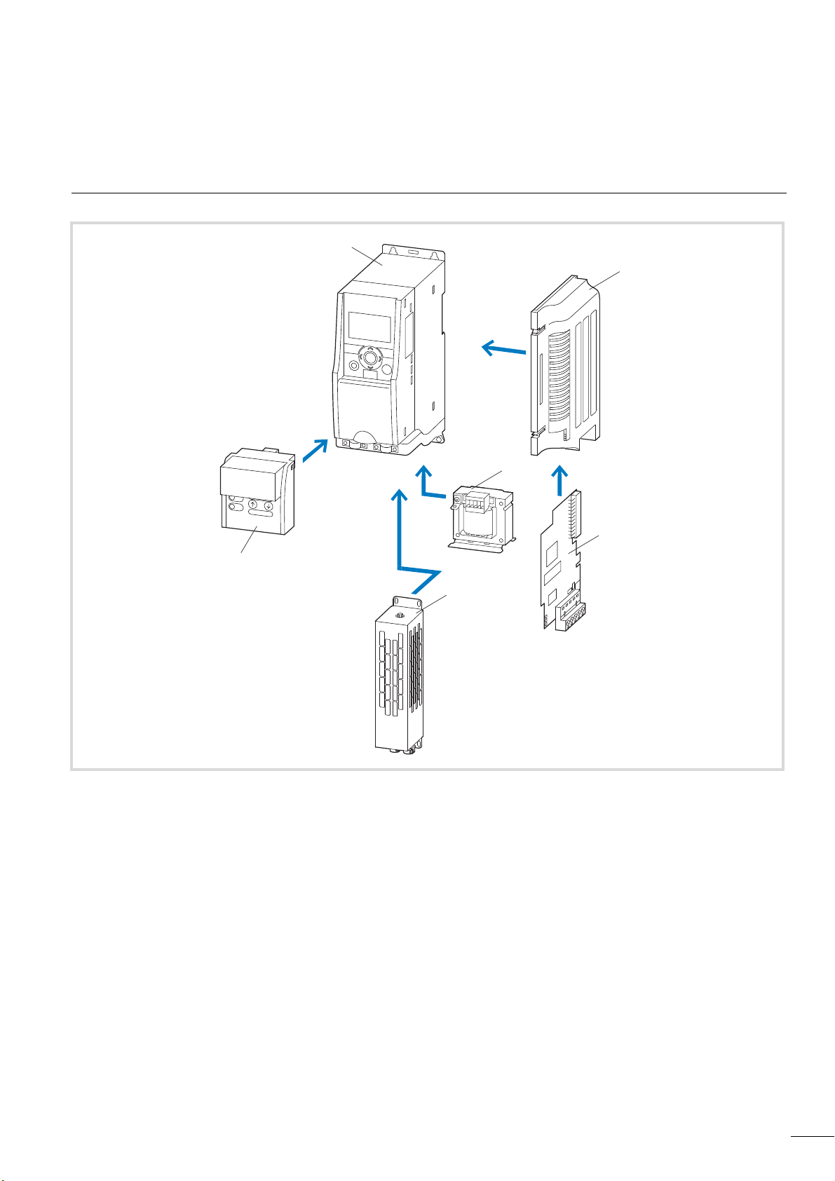
1M-MaxTM Series
System overview
Figure 3: System overview
a Frequency inverters MMX-…
b Mounting frame (for fieldbus connection) MMX-NET-XA
c Fieldbus connection
CANopen XMX-NET-CO-A
PROFIBUS DP with XMX-NET-PS-A screw terminals
PROFIBUS DP with XMX-NET-PD-A Sub-Dm connector
DeviceNet XMX-NET-DN-A
d DEX-LN… mains reactor, DEX-LM3… motor reactor, SFB400… sinusoidal filter
e BR… braking resistor
f Communication module MMX-COM-PC
9
M-MaxTM Series
I
OK
BACK
RESET
LOC
REM
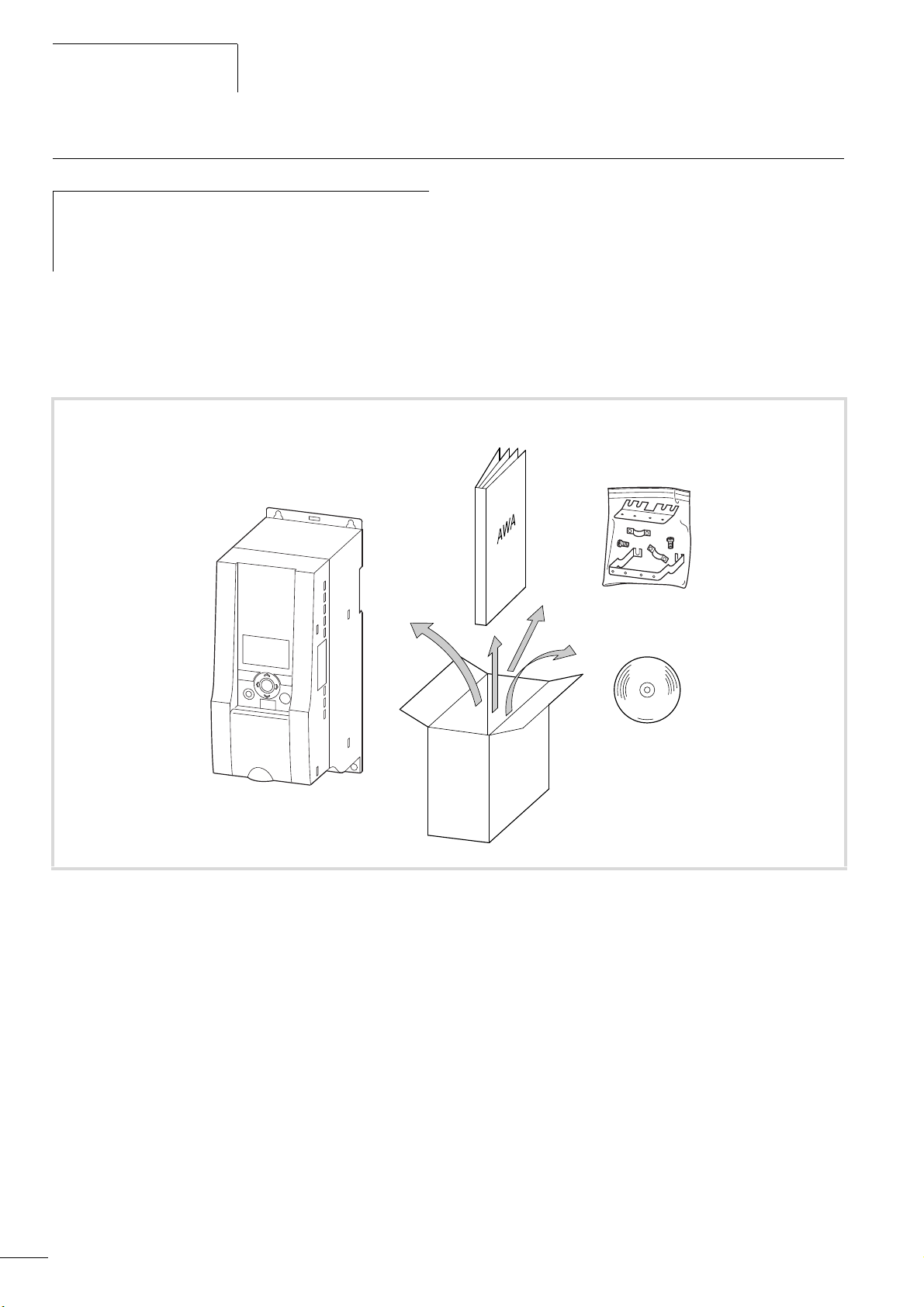
Checking the Delivery
04/10 MN04020001Z-EN
Before opening the packaging go over the ratings plate on
h
the packaging and check for whether the delivered
frequency inverter is the same type as the one you
ordered.
M-MAXTM frequency converters have been carefully packaged and
prepared for delivery. These devices should only be shipped in their
original packaging with suitable transportation materials. Please
take note of the labels and instructions on the packaging, as well
as of those meant for the unpacked device.
Open the packaging with adequate tools and inspect the contents
immediately after receipt in order to ensure that they are complete
and undamaged.
The packaging must contain the following parts:
TM
• a M-Max
frequency inverter,
• an accessory kit for EMC-suitable installation
• Installation instructions AWA8230-2416
TM
• a data carrier (CD-ROM) with documentation for M-Max
CD
.
Figure 4: Scope of supply
10
04/10 MN04020001Z-EN
a
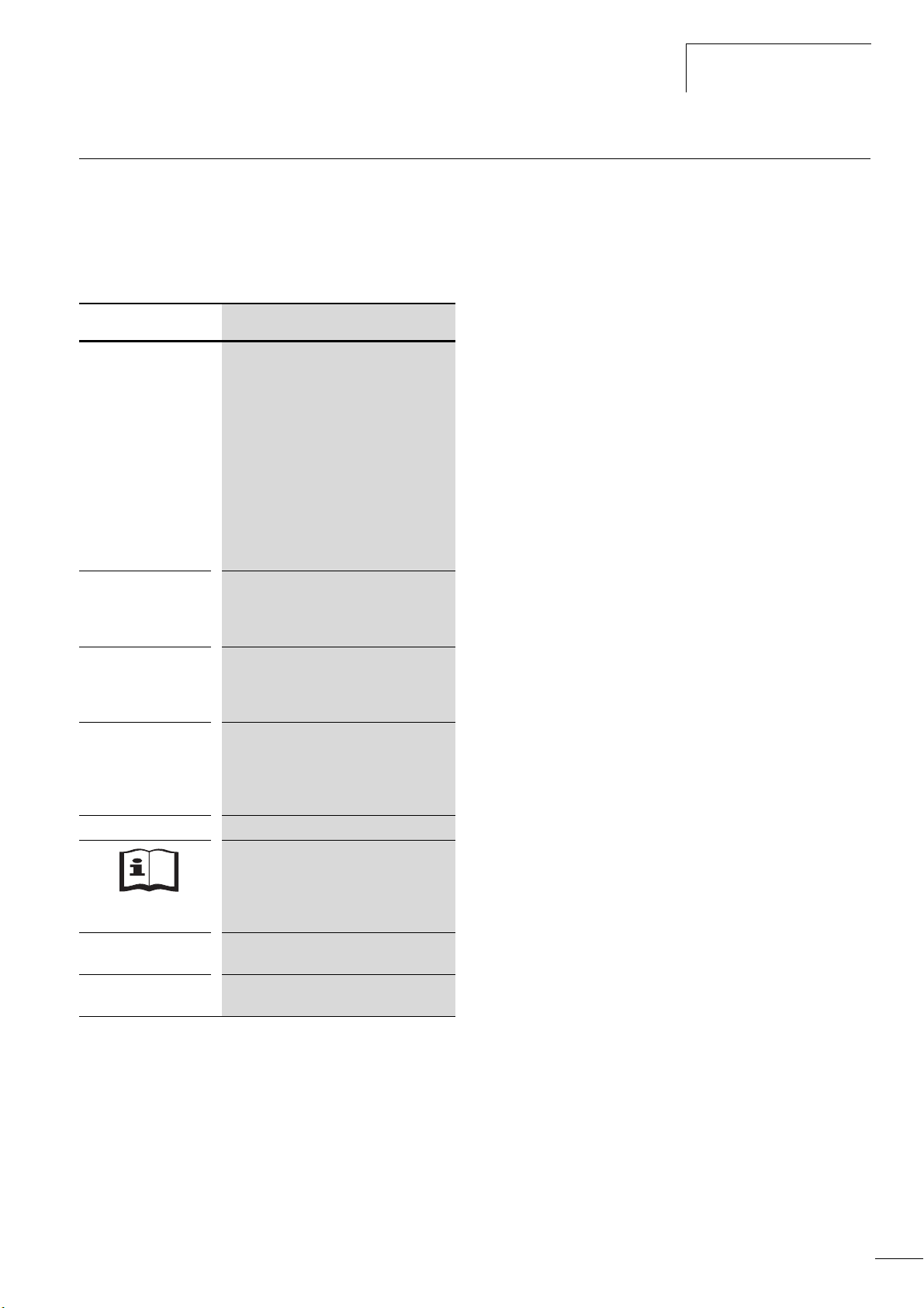
Rating data on the nameplate
The device specific rating data of the M-Max
TM
is shown on the
nameplate on the side of the device and on the rear of the control
signal terminal cover.
The inscription of the nameplates has the following meaning
(example):
Label Meaning
Rating data on the nameplate
MMX34AA3D3F0-0 Part no.:
MMX = frequency inverter of the M-Max
series
3 = Three-phase power connection
4 = 400 V voltage category
AA = Instance (Software version A and
alphanumerical display)
3D3 = 3.3 A rated operational current
(3-decimal-3)
F = Integrated radio interference
suppression filter
0 = IP20 protection type
0 = No integrated optional assembly
Input
Output Load side (motor) rating:
Power Assigned motor rating.
S/N Serial number
IP 20/Open type
12W10
Power connection rating:
Three-phase AC voltage (U
380 - 480 V voltage, 50/60 Hz frequency,
input phase current (4.0 A)
Three-phase AC voltage (0 - U
phase current (3.3 A), output frequency
(0 - 320 Hz)
1.1 kW at 400 V/1.5 HP at 460 V for a
four-pole internally-cooled or surfacecooled three-phase asynchronous motor.
(1500 min
Frequency inverter is an electrical apparatus.
Read the manual (in this case
AWB8230-1603) before making any
electrical connections and commissioning.
Protection type of the housing: IP 20, UL
(cUL) Open type.
manufacturing date
Week 12 of 2010.
-1
at 50 Hz/ 1800 rpm at 60 Hz)
3~ AC),
e
), output
e
TM
11
M-MaxTM Series
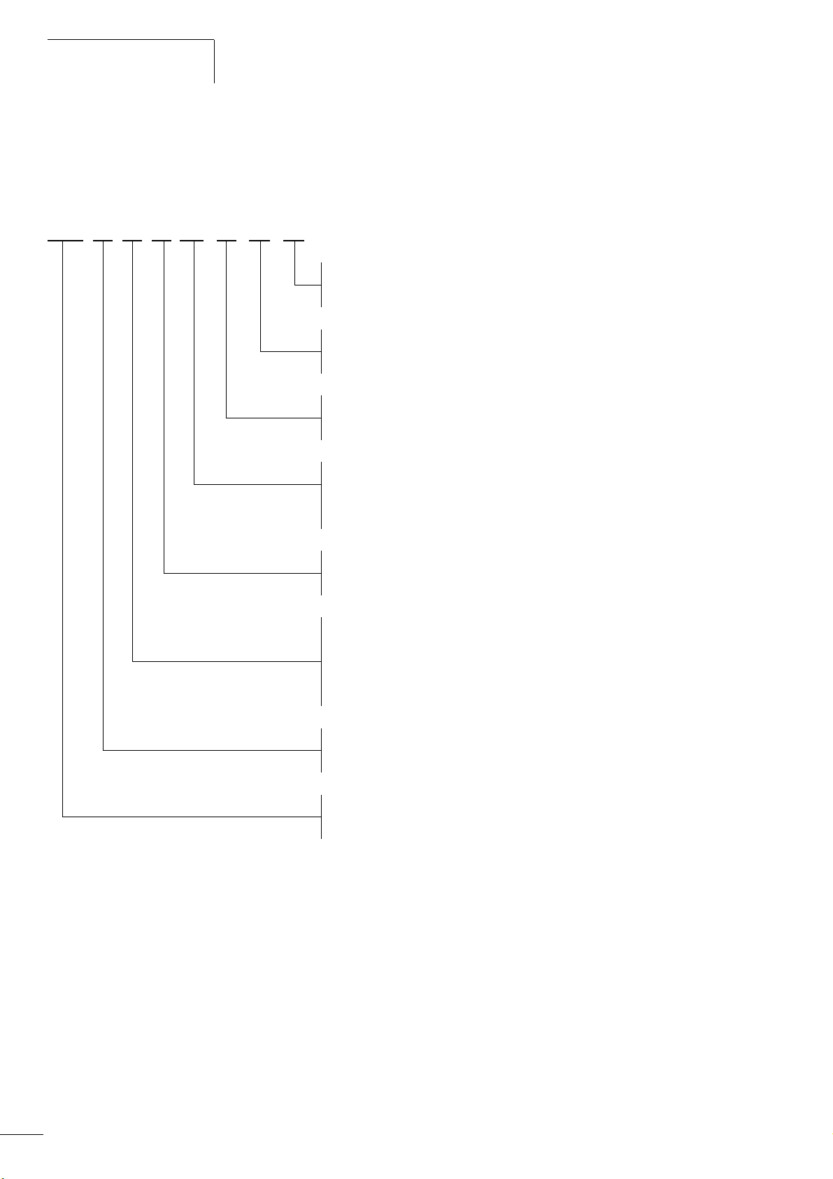
Key to part numbers
The type designation code and the part no. of the M-MAX
TM
frequency inverter series are in the following order:
MMX 3 4 AA 1D3 F 0 -0 Explanation
0 = No optional assembly integrated
1 = Optional assembly integrated
0 = IP20 protection type
1 = Protection type IP21, NEMA 1
F = Radio noise filter (internal)
N = Without internal radio noise filter (No filter)
04/10 MN04020001Z-EN
Voltage class
1 = 100 V (110 V -15 % - 115 V +10 %)
2 = 200 V (208 V -15 % - 240 V +10 %)
4 = 400 V (380 V -15 % - 480 V +10 %)
1 = Single-phase power supply
3 = Three-phase mains supply voltage
Figure 5: Type designation of the M-Max
Rated operational current
1D3 = 1.3 A (D = decimal)
011 = 11 A
AA = Specification (Software version, display unit)
MMX = frequency inverter of the M-Max
TM
frequency inverters
TM
series
12

04/10 MN04020001Z-EN
Rating data on the nameplate
Examples
Label Meaning
MMX11AA2D8N0-0 MMX = frequency inverter of the M-Max
series:
1 = Single-phase power supply
1 = Rated voltage 115 V
AA = Type of software version and display
unit
2D8 = 2.8 A (rated operational current)
N = No integrated interference suppression
filter (No filter)
0 = IP20 protection type
0 = No integrated optional assembly
MMX12AA1D7F0-0
MMX32AA2D4N0-0
MMX34AA012F0-0
MMX34AA5D6N0-0
MMX = frequency inverter of the M-Max
series:
1 = Single-phase power supply
2 = Rated voltage 230 V
AA = Type of software version and display
unit
1D7 = 1.7 A (rated operational current)
F = Integrated radio noise filter
0 = IP20 protection type
-0 = No integrated optional assembly
MMX = frequency inverter of the M-Max
series:
3 = Three-phase mains supply voltage
2 = Rated voltage 230 V
AA = Type of software version and display
unit
2D4 = 2.4 A (rated operational current)
N = No integrated interference suppression
filter (No filter)
0 = IP20 protection type
-0 = No integrated optional assembly
MMX = frequency inverter of the M-Max
series:
3 = Three-phase mains supply voltage
4 = Rated voltage 400 V
AA = Type of software version and display
unit
012 = 12 A (rated operational current)
F = Integrated radio noise filter
0 = IP20 protection type
-0 = No integrated optional assembly
MMX = frequency inverter of the M-Max
series:
3 = Three-phase mains supply voltage
4 = Rated voltage 400 V
AA = Type of software version and display
unit
5D6 = 5.6 A (rated operational current)
N = No integrated interference suppression
filter (No filter)
0 = IP20 protection type
-0 = No integrated optional assembly
TM
TM
TM
TM
TM
MMX… N…: An externally fitted interference suppres-
h
sion filter is required for operation in accordance with IEC/
EN 61800-3.
Example: MMX34AA5D6N0-0.
Assigned interference suppression filter: MMX-LZ3-009
(three-phase interference suppression filter up to 9 A, size FS2)
MMX11: The mains voltage of 115 V is raised to 230 V
h
(output voltage) through an internal voltage double
connection.
13
M-MaxTM Series
General rated operational data
04/10 MN04020001Z-EN
Technical data Symbols
Unit Value
used in
technical
data and
formulae
General
Standards EMC: IEC/EN 61800-3,
Safety: IEC/EN61800-5, UL508C
Certifications and manufacturer's declarations on
conformity
EMC: CE, CB, c-Tick
Safety: CE, CB, UL, cUL
Production quality RoHS, ISO 9001
Climatic proofing p
w
% < 95 %, average relative humidity, non-condensing (EN50178)
Air quality
Chemical vapors IEC721-3-3: Device in operation, Class 3C2
Mechanical particles IEC721-3-3: Device in operation, Class 3S2
Ambient temperature
Operation i °C -10 - +40 (+501))
Storage i °C -40 - +70
Installation altitude H m 0 – 1000 m above sea level, over 1000 m with 1% power reduction per
100 m, maximum 2000 m, at maximum +50 °C ambient temperature
Mounting position Vertical ±90
Protection type IP20
Busbar tag shroud BGV A3 (VBG4, finger and back-of-hand safe)
Overvoltage category/pollution degree -
Mechanical shock resistance IEC 68-2-27
Storage and transport: 15 g, 11 ms (in the packaging)
UPS drop test (for applicable UPS weights)
Vibration EN 60068-2-6
3 – 150 Hz, oscillation amplitude 1 mm (Peak) at 3 – 15.8 Hz,
maximum acceleration amplitude 1 g at 15.8 – 150 Hz
Emitted interference with internal EMC filter
(maximum motor cable length)
C2: Class A in 1st environment (residential area with commercial
utilization)
C3: Class A in 2nd environment (Industrial)
MMX11, MMX12
C2, C3
MMX32, MMX34 C2, C3
Power section
Rated operational voltage f
MMX11 U
MMX12 U
MMX32 U
MMX34 U
Mains network configuration (AC power supply
network)
LN
e
e
e
e
Hz at 50/60
VAC 1~115(110-15%-120 +10%)
VAC 1~230(208-15%-240 +10%)
VAC 3~230(208-15%-240 +10%)
VAC 3~400(380-15% - 480 +10%)
Center-point grounded star network (TN-S network)
Phase grounded AC networks are not permitted.
Mains switch-on frequency Maximum one time per minute
Mains current THD %
Short-circuit current I
K
kA maximum < 50
> 120
14
04/10 MN04020001Z-EN
Rating data on the nameplate
Technical data Symbols
Unit Value
used in
technical
data and
formulae
Mains frequency f
Pulse frequency (switching frequency of the
LN
f
PWM
Hz 50/60, (45 - 66 Hz ±0 %)
kHz 1-16 (FS: 6kHz)
1)
inverter)
Operating mode V/f characteristic curve control (FS), speed control with slip
compensation.
Output voltage U
Output frequency f
2
2
V 3 AC 230 (MMX11), 3 AC Ue (MMX12, MMX32, MMX34)
Hz 0 - 320 (FS: 0 - 50 Hz)
Frequency resolution (setpoint value) I Hz 0.01
Rated operational current I/I
Overload current I/I
Starting current I/I
e
e
e
Braking torque MB/M
N
% 100 % continuous current at maximum +50 °C ambient temperature
% 150 for 60 s every 600 s
% 200 for 2 s every 20 s
% F 30 for all sizes
up to maximum 100 % MN only as of size MMX34…4D3... with external
braking resistance
Control section
Control voltage (output) U
Reference voltage (output) U
c
s
VDC 24, max. 50 mA
VDC 10, max. 10 mA
Input, digital, parameter definable 6 x, max. +30 V DC, Ri > 12 kO
Permitted residual ripple with external
max. 5 % DUa/U
a
control voltage (+24 V)
Input, analog, parameterizable, selection via
2 x 0 (2) - +10 VDC, Ri> 200 kO or 0 (4) - 20 mA, RB~ 200 O
microswitches
Resolution Bit 10
Output, analog, parameter definable
1 x 0 (2) - 10 V, max. 10 mA
Resolution Bit 10
Output, digital, parameter definable 1 x Transistor: 48 V DC, max. 50 mA
Output relay, parameter definable
1 x N/O: 250 V AC, maximum 2 A or
250 V DC, max. 0.4 A
Output relay, parameter definable
1 x Changeover contact: 250 V AC, maximum 2 A or 250 V DC,
maximum 0.4 A
Serial interface RS485/Modbus RTU
1) +50 °C with lateral clearance of f 20 mm and reduced pulse frequency F 4kHz.
MMX34AA014… is only permissible for a maximum ambient temperature of +40 °C at a max. pulse frequency of F 4kHz.
15
M-MaxTM Series
Technical data
04/10 MN04020001Z-EN
Part no. Rated current Overload
current
Assigned motor rating Installation
size
(150 %)
I
e
[A] [A] [kW] [A]
I
e150
P
(230 V, 50 Hz)
P
(230 V, 60 Hz)
1)
[HP] [A]
1)
Power connection voltage: 1 AC 115 V, 50/60 Hz
(94-132V
MMX11AA1D7… 1.7 2.6 0.25 1.4 1/3
MMX11AA2D4…
MMX11AA2D8…
MMX11AA3D7… 3.7 5.6 0.75 3.2 3/4 3.2 FS2
MMX11AA4D8… 4.8 7.2 1.1 4.6 1 4.2 FS3
1) Rated motor currents for normal four-pole internally and surface-cooled three-phase asynchronous motors (1500 rpm at 50 Hz, 1800rpm at 60 Hz).
2) Calculated motor output (no standard value).
g0%, 45-66Hz g0%)
2.4 3.6 0.37 2 1/2 2.2 FS2
2.8 4.2 0.55 2.7 1/2 2.2 FS2
2)
1.5
2)
FS2
The mains voltage of 115 V is raised to 230 V (output voltage) through an internal voltage double connection.
Part no. Rated current Overload
current
(150 %)
I
e
I
e150
[A] [A] [kW] [A]
Assigned motor rating Installation
size
P
(230 V, 50 Hz)
1)
P
(230 V, 60 Hz)
[HP] [A]
1)
Power connection voltage: 1 AC 230 V, 50/60 Hz
(177 - 264 V
MMX12AA1D7… 1.7 2.6 0.25 1.4 1/3
MMX12AA2D4…
MMX12AA2D8… 2.8 4.2 0.55 2.7 1/2 2.2 FS1
MMX12AA3D7…
MMX12AA4D8… 4.8 7.2 1.1 4.6 1 4.2 FS2
MMX12AA7D0… 7 10.5 1.5 6.3 2 6.8 FS2
MMX12AA9D6… 9.6 14.4 2.2 8.7 3 9.6 FS3
g0 %, 45 - 66 Hz g0 %)
2.4 3.6 0.37 2 1/2 2.2 FS1
3.7 5.6 0.75 3.2 3/4 3.2 FS2
2)
1.5
2)
FS1
Power connection voltage: 3AC 230 V, 50/60 Hz
(177 - 264 V
MMX32AA1D7… 1.7 2.6 0.25 1.4 1/3
MMX32AA2D4… 2.4 3.6 0.37 2 1/2 2.2 FS1
MMX32AA2D8… 2.8 4.2 0.55 2.7 1/2 2.2 FS1
MMX32AA3D7… 3.7 5.6 0.75 3.2 3/4 3.2 FS2
MMX32AA4D8… 4.8 7.2 1.1 4.6 1 4.2 FS2
MMX32AA7D0… 7 10.5 1.5 6.3 2 6.8 FS2
MMX32AA011… 11 14.4 2.2 8.7 3 9.6 FS3
1) Rated motor currents for normal four-pole internally and surface-cooled three-phase asynchronous motors (1500 rpm at 50 Hz, 1800 rpm
2) Calculated motor output (no standard value).
g0 %, 45 - 66 Hz g0 %)
2)
1.5
2)
FS1
at 60 Hz).
16
04/10 MN04020001Z-EN
Rating data on the nameplate
Part no. Rated current Overload
current
Assigned motor rating Installation
size
(150 %)
I
e
[A] [A] [kW] [A]
I
150
P
(400 V, 50 Hz)
P
(460 V, 60 Hz)
1)
[HP] [A]
1)
Power connection voltage: 3AC 400 V, 50/60 Hz
(323 - 528 V
MMX34AA1D3… 1.3 2 0.37 1.1 1/2 1.1 FS1
MMX34AA1D9… 1.9 2.9 0.55 1.5 3/4 1.6 FS1
MMX34AA2D4… 2.4 3.6 0.75 1.9 1 2.1 FS1
MMX34AA3D3… 3.3 5 1.1 2.6 1-1/2 3 FS2
MMX34AA4D3… 4.3 6.5 1.5 3.6 2 3.4 FS2
MMX34AA5D6… 5.6 8.4 2.2 5 3 4.8 FS2
MMX34AA7D6… 7.6 11.4 3 6.6 4
MMX34AA9D0…
MMX34AA012… 12 18 5.5 11.3 7-1/2 11 FS3
MMX34AA014… 14 21 7.5
1) Rated motor currents for normal four-pole internally-cooled and surface-cooled three-phase asynchronous motors (1500 min
at 60 Hz)
2) Calculated motor output (no standard value).
3) Operation with reduced load torque (about -10 % M
4) Allocated motor output at a maximum ambient temperature of +40 °C and a maximum pulse frequency of 4 kHz.
g0 %, 45 - 66 Hz g0 %)
9 13.5 4 8.5 5 7.6 FS3
2)
2)
)
N
(15.2)
3)
10
4)
2)
6.4
FS3
14 FS3
-1
at 50 Hz, 1800 min
-1
17
M-MaxTM Series
g
h
i
j
a
b
c
d
f
e
I
OK
BACK
RESET
LOC
REM
04/10 MN04020001Z-EN
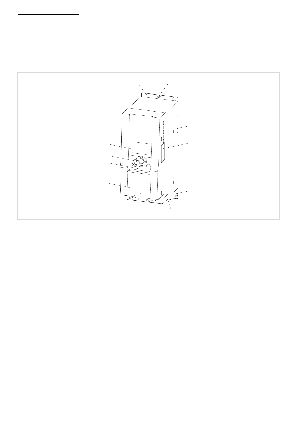
Description of the M-Max
TM
The following drawing shows an M-Max
TM
device.
Figure 6: Description of the M-Max
TM
a Mounting holes (screw fastening)
b Release (removal from mounting rail)
c Recess for mounting on mounting rail (DIN EN 50022-35)
d Interface for fieldbus connection modules (Option, MMX-NET-XA)
e EMC installation accessories
f Power section terminals
g Cover flap of control signal terminals and microswitches
h Interface for PC connection module MMX-COM-PC (Option)
i Keypad with 9 control buttons
j Display unit (LCD)
Features
The M-Max
TM
frequency inverter convert the voltage and
frequency of an existing AC network into a DC voltage. This DC
voltage is used to generate a three-phase AC voltage with
adjustable frequency and assigned amplitude values for the
variable speed control of three-phase asynchronous motors.
18
04/10 MN04020001Z-EN
ba
c
f
g
h
de
+
R+
EMC
L1
L2/N
L3
PE
R-
M
3
h
i
U/T1
V/T2
W/T3
PE
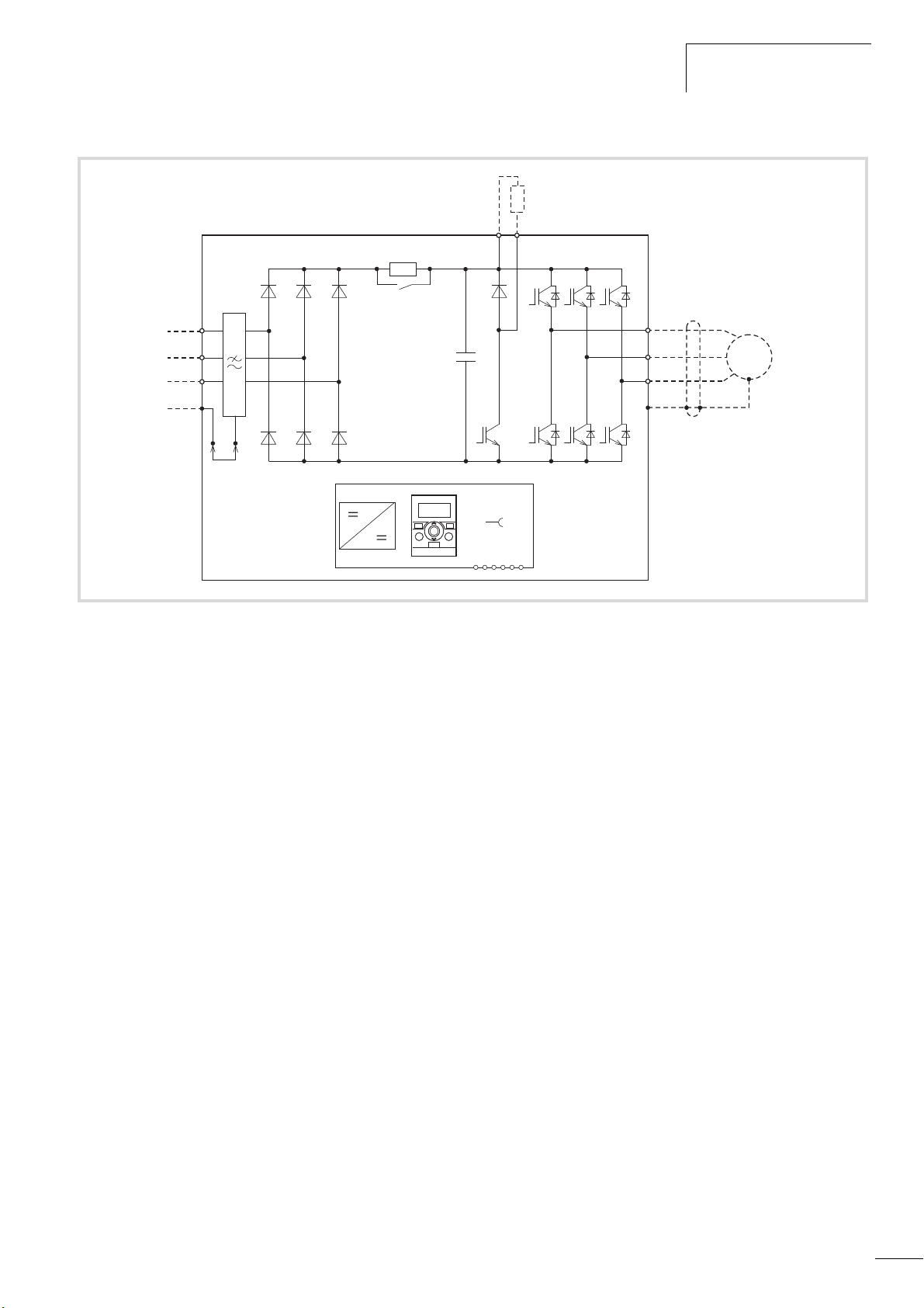
Features
Figure 7: Block diagram, elements of the M-MaxTM frequency inverters
a Supply L1, L2/N, L3, PE, mains supply voltage U
LN=Ue
at 50/60 Hz:
MMX11: 100 V class, single-phase mains connection (1 AC 120 V),
MMX12: 200 V class, single-phase mains connection (1 AC 230 V/240 V),
MMX32: 200 V class, three-phase mains connection (3 AC 230 V/240 V),
MMX34: 400 V class, three-phase mains connection (3 AC 400 V/480 V).
b Internal interference suppression filter (MMX... F...), category C2 and C3, to IEC/EN 61800-3. EMC-connection of internal interference suppression
filter to PE.
c Rectifier bridge, single phase (MMX1…) or three-phase (MMX3…), converts the AC voltage of the electrical network into DC voltage.
d DC link with charging resistor, capacitor and switching mode power supply unit (SMPS = Switching Mode Power Supply):
DC link voltage U
with single-phase mains connection (1 AC): UDC= 1.41 x U
DC
LN
DC link voltage UDCwith three-phase mains connection (3 AC): UDC= 1.35 x ULN.
e Inverter. The IGBT based inverter converts the DC voltage of the DC link (U
frequency (f
f Motor connection U/T1, V/T2, W/T3 with output voltage U
output current (I
). Sinusoidal pulse width modulation (PWM) with V/f control can be switched to speed control with slip compensation.
2
(0 to 100 % Ue) and output frequency f2 (0 to 320 Hz)
):
2
2
) into a three-phase AC voltage (U2) with variable amplitude and
DC
MMX11: 1.7 A - 4.8 A,
MMX12: 1.7 A - 9.6 A,
MMX32: 1.7 A - 11 A,
MMX34: 1.3 A - 14 A.
100 % at an ambient temperature of +50 °C with an overload capacity of 150 % for 60 s every 600 s and a starting current of 200 % for 2 s every
20 s.
g Keypad with control buttons, LCD display, control voltage, control signal terminals, microswitches and interface for the PC interface module (Option).
h Braking transistor: connections R+ and R- for external braking resistance (only with MMX34 / at 3.3 A).
i Three-phase asynchronous motor, variable speed control of three-phase asynchronous motor for assigned motor shaft power values (P
MMX11: 0.25 - 1.1 kW (230 V, 50 Hz) or 0.33 - 1 HP (230 V, 60 Hz),
MMX12: 0.25 - 2.2 kW (230 V, 50 Hz) or 0.25 - 3 HP (230 V, 60 Hz),
MMX32: 0.25 - 2.2 kW (230 V, 50 Hz) or 0.25 - 3 HP (230 V, 60 Hz),
MMX34: 0.37 - 7.5 kW (400 V, 50 Hz) or 0.5 - 10 HP (460 V, 60 Hz).
):
2
19
M-MaxTM Series
230 / 400 V d / Y
4.0 / 2.3
0,75
0.67
j
cos
kW
min
-1
1410 50 Hz
A
b
c
a
U, I, f
I
OK
BACK
RESET
LOC
REM
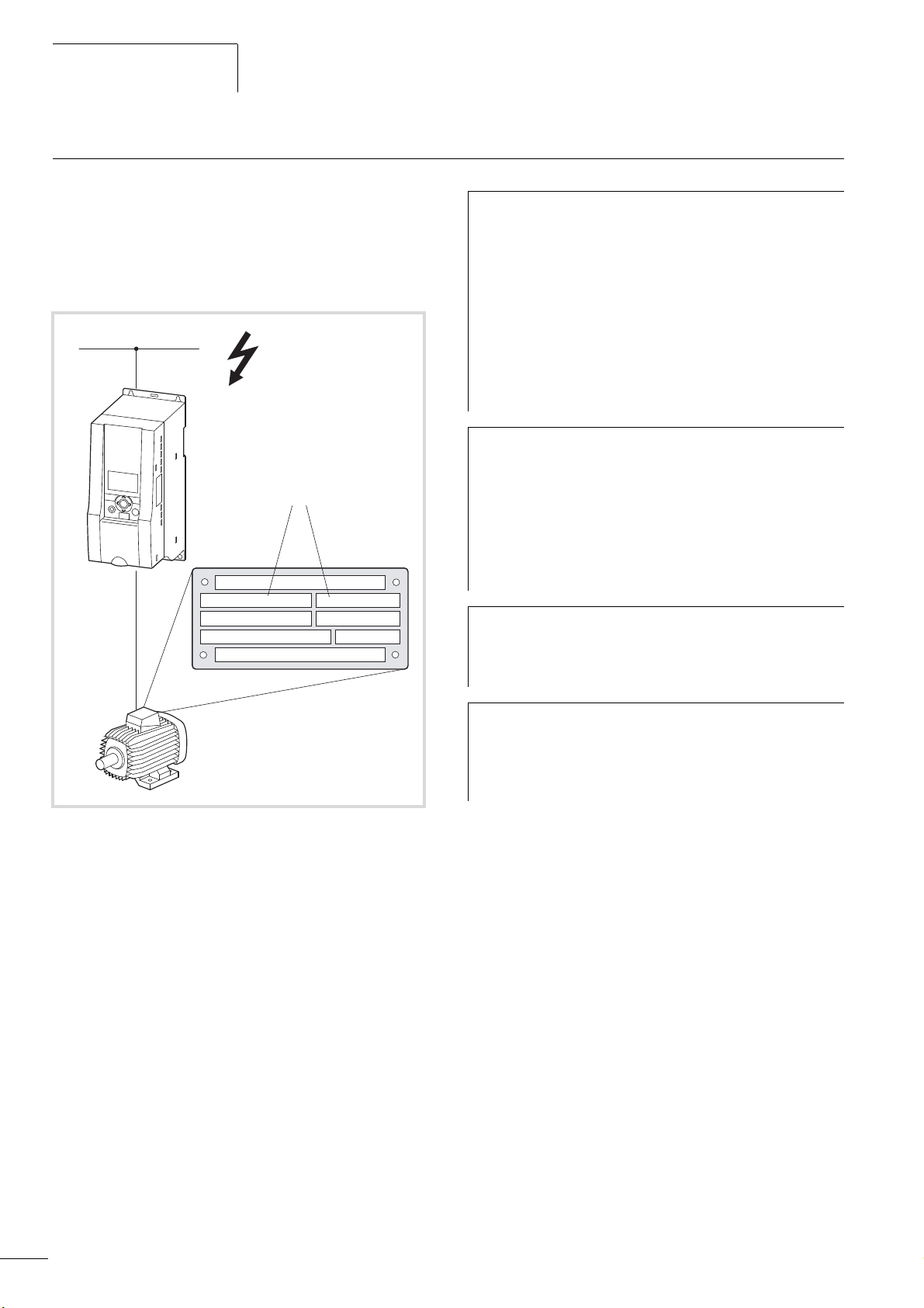
Selection criteria
04/10 MN04020001Z-EN
The frequency inverter c is selected according to the supply
voltage U
assigned motor b. The circuit type (
of the mains supply a and the rated current of the
LN
D / Y) of the motor must be
selected according to the supply voltage a. The rated output
current I
of the frequency inverter must be greater than/equal to
e
the rated motor current.
When connecting multiple motors in parallel to the output
h
of a frequency inverter, the motor currents are added
geometrically – separated by effective and idle current
components. When you select a frequency inverter, make
sure that it can supply the total resulting current. If necessary, for dampening and compensating the deviating
current values, motor reactors or sinusoidal filters must be
connected between the frequency inverter and the motor.
The parallel connection of multiple motors in the output
of the frequency inverter is only permitted with U/f-characteristic curve control.
If you connect a motor to an operational frequency
h
inverter, the motor draws a multiple of its rated
operational current. When you select a frequency inverter,
make sure that the starting current plus the sum of the
currents of the running motors will not exceed the rated
output current of the frequency inverter.
Switching in the output of the frequency inverter is only
permitted with U/f-characteristic curve control.
The speed control with slip compensation (P11.8)
h
increases the drive dynamics and optimizes the output.
For this the frequency inverter processes all motor data in
an electrical image.
Figure 8: Selection criteria
When selecting the drive, the following criteria must be known:
• Type of motor (three-phase asynchronous motor)
• Mains voltage = rated operating voltage of the motor
(e.g. 3 AC ~ 400 V),
• Rated motor current (guide value, dependent on the circuit type
and the supply voltage)
• Load torque (quadratic, constant),
• Starting torque,
• Ambient temperature (rated value +40 °C).
The speed control operating mode (P11.8) must only be
h
used with single drives (one motor at the output of the
frequency inverter). The rated current of the motor must
be assigned to the rated operational current of the
frequency inverter (same rating).
20

04/10 MN04020001Z-EN
Proper use
The M-MAX
TM
frequency inverters are not domestic appliances.
They are designed only for industrial use as system components.
The M-Max
TM
frequency inverters are electrical apparatus for
controlling variable speed drives with three-phase motors. They
are designed for installation in machines or for use in combination
with other components within a machine or system.
After installation in a machine, the frequency inverters must not be
taken into operation until the associated machine has been
confirmed to comply with the safety requirements of Machinery
Safety Directive (MSD) 89/392/EEC (meets the requirements of
EN 60204). The user of the equipment is responsible for ensuring
that the machine use complies with the relevant EU Directives.
TM
The CE markings on the M-MAX
frequency inverter confirm
that, when used in a typical drive configuration, the apparatus
complies with the European Low Voltage Directive (LVD) and the
EMC Directives (Directive 73/23/EEC, as amended by 93/68/EEC
and Directive 89/336/EEC, as amended by 93/68/EEC).
TM
In the described system configurations, M-MAX
frequency
inverters are suitable for use in public and non-public networks.
Proper use
A connection to IT networks (networks without reference to earth
potential) is permissible only to a limited extent, since the device’s
built-in filter capacitors connect the network with the earth potential (enclosure). On earth free networks, this can lead to
dangerous situations or damage to the device (isolation monitoring required).
To the output of the frequency inverter (terminals U, V, W)
h
you must not:
• connect a voltage or capacitive loads (e.g. phase
compensation capacitors),
• connect multiple frequency inverters in parallel,
• make a direct connection to the input (bypass).
Observe the technical data and connection requirements. For
additional information, refer to the equipment nameplate or label
at the frequency inverter and the documentation.
Any other usage constitutes improper use.
21
M-MaxTM Series
04/10 MN04020001Z-EN
Maintenance and inspection
Provided that the general rating data (see Section “Rating data on
the nameplate”, page 14) and the special technical data
( a section “Special technical data” in the Appendix) of the
TM
ratings concerned are observed, the M-Max
frequency inverters
function and the lifespan of the M-Max
therefore recommend that the devices are checked regularly and
the following maintenance measures are carried out at the
specified intervals.
TM
frequency inverter. We
are maintenance free. However, external influences may affect the
Maintenance measures Maintenance interval
Clean cooling vents (cooling slits) If required
Check the fan function 6 - 24 months (depending on the environment)
Filter in the switching cabinet doors (see manufacturer specifications) 6 - 24 months (depending on the environment)
Check the tightening torques of the terminals (control signal terminals, power
terminals)
Check connection terminals and all metallic surfaces for corrosion 6 - 24 months (depending on the environment)
Charge capacitors 12 months, see Section “Charging DC link capacitors”
Regularly
There are no plans for replacing or repairing individual
TM
components of M-Max
If the M-Max
TM
frequency inverter is damaged by external
frequency inverters.
influences, repair is not possible. Dispose of the device in
accordance with the respectively applicable environmental laws
and provisions for the disposal of electrical or electronic devices.
Storage
If the frequency inverter is stored before use, suitable ambient
conditions must be ensured at the site of storage:
• Storage temperature: -40 - +70 °C,
• Relative average air humidity: < 95 %, non condensing
(EN 50178),
• To prevent damage to the DC link capacitors, storage times
longer than 12 months are not recommended (see Section
“Charging DC link capacitors”).
Charging DC link capacitors
After long storage times or long down times without a power
supply (> 12 months), the capacitors in the DC link must undergo
controlled recharging, in order to avoid damage.
For this the M-Max
TM
frequency inverters must be fed with a
regulated DC power supply unit via two mains connection
terminals (e.g. L1, L2/N). To avoid any possible excessive leakage
currents from the capacitors, the inrush current should be limited
to around 300 to 800 mA (depending on the rating). In this case,
the frequency inverter must not be enabled (no start signal). The
DC voltage must then be set to the values of the corresponding DC
link voltage (U
) and fed for around two hours (regeneration
DC
time).
MMX11: Due to the internal voltage doubler circuit, the
h
capacitors cannot be recharged via the connection
terminals. Contact your local sales partner.
Service and warranty
In the unlikely event that you have a problem with your Moeller M-
TM
Max
frequency inverter, please contact your local sales office.
When you call, have the following information ready:
• the exact frequency inverter part no.
(see nameplate),
• the date of purchase,
• a detailed description of the problem which has occurred with
the frequency inverter.
If some of the information printed on the nameplate is not legible,
please state only the information which is clearly legible.
Information concerning the guarantee can be found in the Moeller
General Terms and Conditions of Sale.
24-hour hotline: +49 (0)1805 223 822
E-Mail: FieldserviceEGBonn@Eaton.com
• MMX12, MMX32 about 324 V DC (= 1.41 x U
phase line-to-line voltage (230 V)
• MMX34 about 540 V DC (= 1.35 x U
to-line voltage (400 V).
22
) with single-
LN
) with three-phase line-
LN
04/10 MN04020001Z-EN
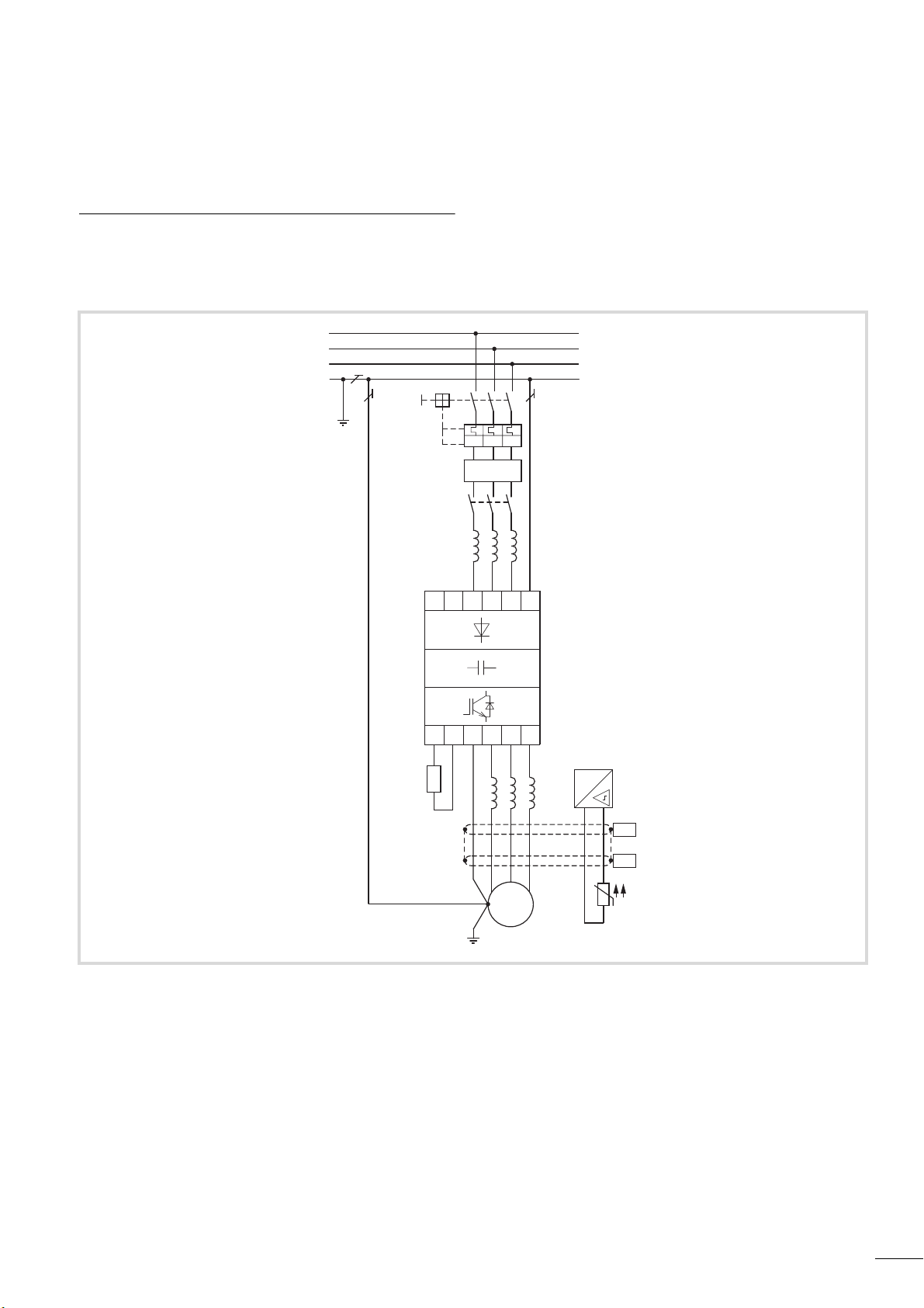
2 Engineering
Introduction
This chapter describes the most important features in the energy
circuit of a drive system (PDS = Power Drive System), which you
should take into consideration in your project planning.
L1
L2
a
L3
PE
b
c
I > I > I >
RCD
k
d
e
R+ R-
L1 L2/N
PE
U
L3 PE
VW
M
3
˜
j
g
f
#
h
PES
i
PES
i
Figure 9: Drive system (PDS)
a Network configuration, mains voltage, mains frequency, interaction with p.f. correction systems
b Fuses and cable cross-sections, line protection
c Protection of persons and domestic animals with residual-current protective devices
d Mains contactor
e Mains reactor, radio interference suppression filter, mains filters
f Frequency inverter: mounting, installation; power connection; EMC measures; circuit examples
g Motor reactor, du/dt filter, sine-wave filter
h Motor protection; thermistor
i Cable lengths, motor cables, shielding (EMC)
j Motor and application, parallel operation of multiple motors on a frequency inverter, bypass circuit; DC braking
k Braking resistance; dynamic braking
23
Engineering
L2
N
L1
L3
PE
04/10 MN04020001Z-EN
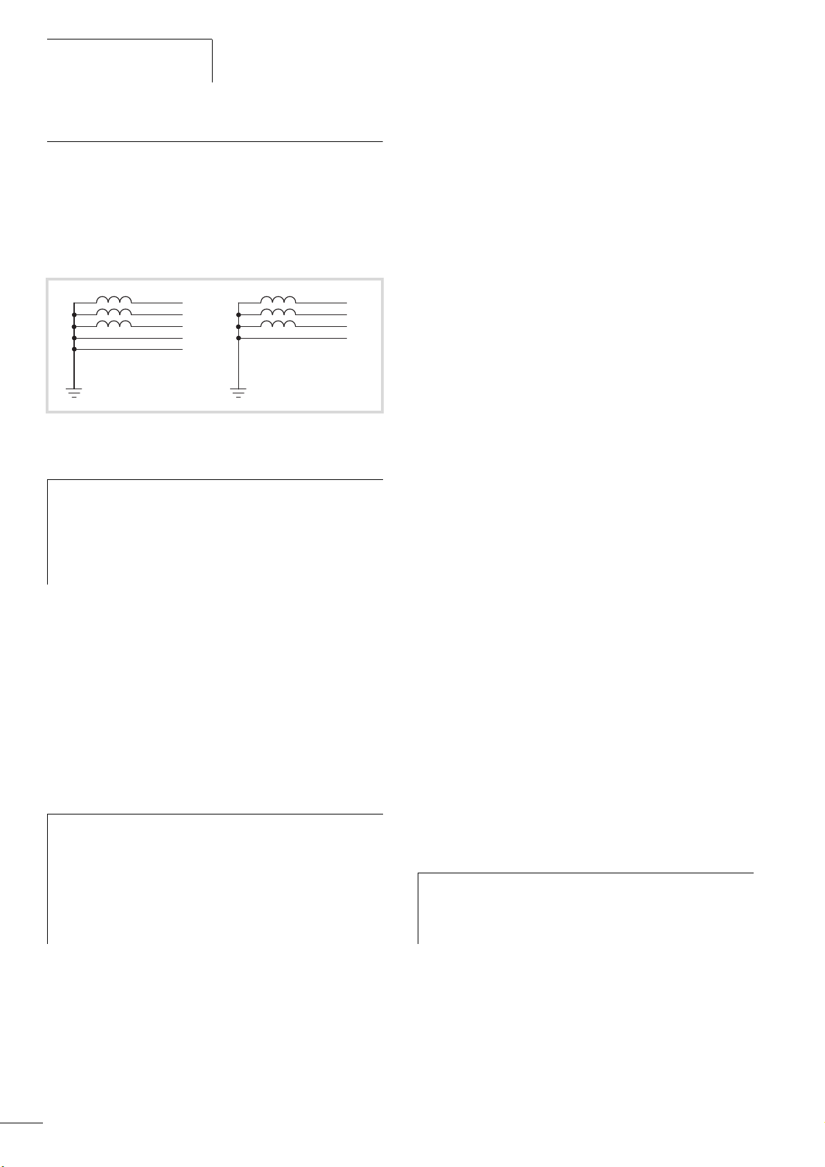
Electrical power network
Mains connection and configuration
TM
The frequency inverters of the M-Max
series can be connected
and operated with all control-point grounded AC power networks
(see IEC 60364 for more information in this regard).
L1
L2
L3
PEN
Figure 10: AC power networks with grounded center point (TN-/TT
networks)
While planning the project, consider a symmetrical
h
distribution to the three external conductors, if multiple
frequency inverters with single phase supplies are to be
connected. The total current of all single phase consumers
is not to cause an overload of the neutral conductor
(N-conductor).
The connection and operation of frequency inverters to
asymmetrically grounded TN networks (phase-grounded Delta
network "Grounded Delta", USA) or non-grounded or highresistance grounded (over 30 O) IT networks is only conditionally
permissible.
TM
If the M-Max
frequency inverters are connected to an
asymmetrically grounded network or to an IT network (non
grounded, insulated), the internal interference suppression filter
must be disconnected (unscrew the screw marked EMC,
a section “Electrical Installation”, page 37).
The required filtering for electromagnetic compatibility (EMC) is
then no longer present.
Measures for electromagnetic compatibility are
h
mandatory in a drive system, to meet the legal
requirements for EMC- and low-voltage regulations.
Mains voltage and frequency
The standardized mains voltages (IEC 60038, VDE017-1) for
energy suppliers (EVU) guarantee the following conditions at the
transition points:
• Deviation from the rated value of voltage:
maximum ±10 %
• Deviation in voltage phase balance: maximum ±3 %
• Deviation from rated value of the frequency:
maximum ±4 %
TM
The broad tolerance band of the M-Max
frequency inverter
considers the rated value for
European as (EU: U
American as (USA: U
= 230 V/400 V, 50 Hz) and
LN
= 240 V/480 V, 60 Hz) standard voltages:
LN
• 120 V, 50/60 Hz at MMX11
• 230 V, 50 Hz (EU) and 240 V, 60 Hz (USA) at MMX12 und
MMX32,
• 400 V, 50 Hz (EU) and 480 V, 60 Hz (USA) at MMX34…
For the bottom voltage value, the permitted voltage drop of 4 %
in the consumer circuits is also taken into account, therefore a
total of U
- 14 %.
LN
• 100 V device class (MMX11):
110 V -15 % - 120 V +10 % (94 V -0 % - 132 V +0 %)
• 200-V device class (MMX12, MMX32):
208 V - -15 % – 240 V + +10 % (177 V - 0 % – 264 V + 0 %)
• 400-V device class (MMX34):
380 V - -15 % – 480 V + +10 % (323 V - 0 % – 528 V + 0 %)
The permitted frequency range is 50/60 Hz here (45 Hz - 0 % – 66
Hz + 0 %).
Voltage balance
Because of the uneven loading on the conductor and with the
direct connection of greater power ratings, deviations from the
ideal voltage form and unsymmetrical voltages can be caused in
three-phase AC power networks. These asymmetric divergences in
the mains voltage can lead to different loading of the diodes in
mains rectifiers with three-phase supplied frequency inverters and
as a result, to an advance failure of this diode.
24
Good grounding measures are a prerequisite for the
effective insert of further measures such as shielding or
filters here. Without respective grounding measures,
further steps are superfluous.
In the project planning for the connection of three-phase
h
supplied frequency inverters (MMX32, MMX34), consider
only AC power networks that handle permitted
asymmetric divergences in the mains voltage F +3 %.
If this condition is not fulfilled, or symmetry at the connection
location is not known, the use of an assigned main choke is
recommended (see “Appendix“, Section “Mains chokes”,
page 169).

04/10 MN04020001Z-EN
K
U
2
2
U+
3
2
U
4
2
U
n
++
2
+
U
1
2
U+
2
2
U
3
2
U
4
2
U
n
++
2
++
-------------------------------------------------------------------------------------------
100%=
THD
U
2
2
U+
3
2
U
4
2
U
n
++
2
+
U
1
------------------------------------------------------------------------------=
Electrical power network
Total harmonic distortion (THD)
The THD (Total Harmonic Distortion) is a measurement for the
occurring harmonic distortion of the sinusoidal oscillation (mains
power side) input variables with the frequency inverter. It is given
in percent of the total value.
U1 = fundamental component
THD k = 0.1 l K = 10 % ~ -20 dB (THD suppression)
THD (Total Harmonic Distortion)
TM
With the frequency inverters of the M-Max
series, the permitted
value for the total harmonic distortion THD >120 %.
Idle power compensation devices
Compensation on the power supply side is not required for the
TM
frequency inverters of the M-MAX
series. From the AC power
supply network they only take on very little reactive power of the
fundamental harmonics (cos
In the AC power networks with non-choked idle current
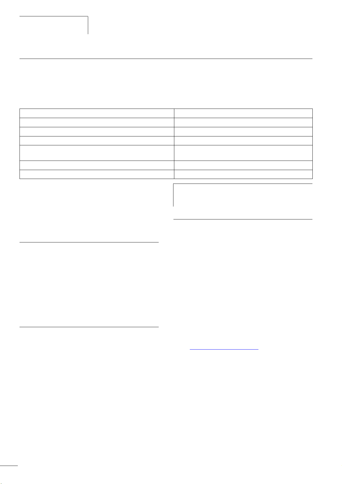
h
v ~ 0.98).
compensation devices, current deviations can enable
parallel resonance and undefinable circumstances.
Mains reactors
A mains reactor (also called commutation inductors) increases the
inductance of the power supply line. This extends the current flow
period and dampens mains deviations.
On frequency inverters, a mains reactor limits the mains feedback
to permissible values. The harmonic current emissions that are fed
back into the mains network ("mains feedback") are reduced. This
reduces the mains-side apparent current to about 30 %.
Towards the frequency inverter, the mains reactors dampen the
interference from the supply network. This increases the withstand
voltage of the frequency inverter and lengthens the lifespan
(diodes of the mains power rectifier, intermediate circuit
capacitors).
For the operation of the M-MAXTM frequency inverter, the
h
application of main chokes is not necessary.
We do recommend however that an upstream main choke
is used since the network quality is not known in most
cases.
While planning the project, consider that a mains reactor
is only assigned to a single frequency inverter for
isolation. Using a large mains reactor for multiple small
frequency inverters should therefore be avoided if at all
possible.
When using an adapting transformer (assigned to a single
frequency inverter), a main choke is not necessary.
Mains reactors are designed based on the mains-side input current
) of the frequency inverter. Mains chokes and the assignment
(I
LN
to M-MAX
TM
frequency inverters are explained in the appendix.
In the project planning for the connection of frequency
inverters to AC power networks with undefined
circumstances, consider using main chokes.
25
Engineering
04/10 MN04020001Z-EN
Safety and switching
Fuses and cable cross-sections
The fuses and wire cross-sections allocated for power-side
connections depend on the rated mains current I
frequency inverter (without mains reactor).
Caution!
h
When selecting the cable cross-section, take the voltage
drop under load conditions into account.
The consideration of other standards (e.g. VDE 0113 or
VDE 0289) is the responsibility of the user.
The recommended fuses and their assignment to the frequency
inverters are listed in page 157 the appendix.
The national and regional standards (for example VDE 0113, EN
60204) must be observed and the necessary approvals (for
example UL) at the site of installation must be fulfilled.
When the device is operated in a UL-approved system, use only
UL-approved fuses, fuse bases and cables.
The leakage currents to ground (to EN 50178) are greater than
3.5 mA. The connection terminals marked PE and the housing
must be connected with the ground circuit.
The leakage currents for the individual performance variables are
listed in the appendix on page 147 ff.
of the
LN
Residual current circuit breakers protect persons and animals from
the existence (not the origination) of impermissibly high contact
voltages. The prevent dangerous, in cases deadly injuries caused
by electrical accidents and also serve as fire prevention.
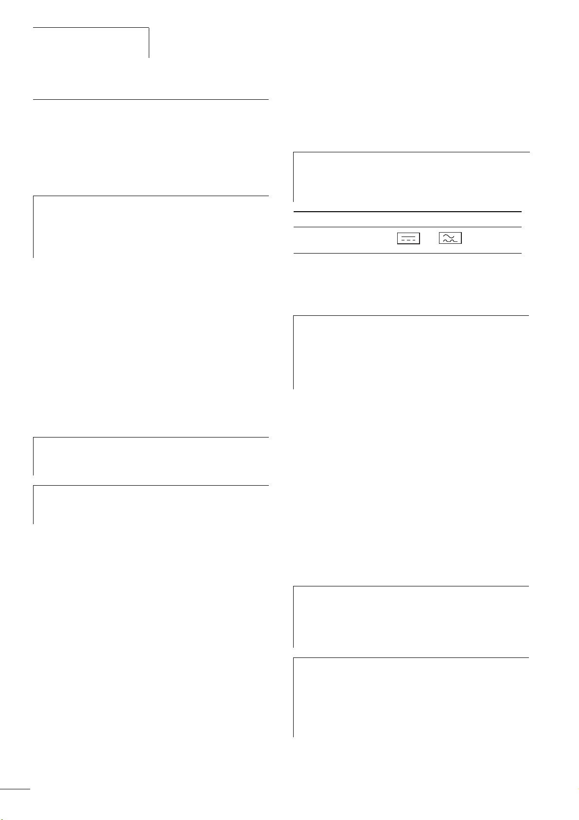
Warning!
j
With frequency inverters, only AC/DC sensitive residual
current circuit breakers (RCD type B) are to be used
(EN 50178, IEC 755).
Identification on the residual-current circuit-breakers
AC/DC sensitive
(RCD, type B)
Frequency inverters work internally with rectified AC currents. If an
error occurs, the DC currents can block an RCD circuit breaker of
type A from triggering and therefore disable the protective
functionality.
Caution!
h
Debounced inputs may not be used in the safety
circuit diagram.
Residual current circuit breakers (RCD) are only to be
installed between the AC power supply network and the
frequency inverter.
Safety-relevant leakage currents can occur while handling and
when operating the frequency inverter, if the frequency inverter is
not grounded (because of a fault).
Caution!
h
The specified minimum PE conductor cross-sections (EN
50178, VDE 0160) must be maintained.
Choose the cross-section of the PE conductor in the motor
h
lines at least as large as the cross-section of the phase
lines (U, V, W).
Cables and fuses
The cross-sections of the cables and line protection fuses used
must correspond with local standards.
For an installation in accordance with UL guidelines, the fuses and
copper cable that are UL-approved and have a heat-resistance of
+60/75 °C are to be used.
Use power cables with insulation according to the specified mains
voltages for the permanent installation. A shielded cable is not
required on the mains side.
A completely (360°) shielded low impedance cable on the motor
side is required. The length of the motor cable depends on the
RFI class and must not exceed 30 m for the M-Max
Residual-current device (RCD)
TM
.
Leakage currents to ground are mainly caused by foreign
capacities with frequency inverters; between the motor phases
and the shielding of the motor cable and via the Y-capacitors of
the noise filter. The size of the leakage current is mainly dependent
upon the:
• length of the motor cable,
• shielding of the motor cable,
• height of the pulse frequency (switching frequency of the
inverter),
• design of the noise filter,
• Grounding measures at the site of the motor.
The leakage current to ground is greater than 3.5 mA with
h
a frequency inverter. Based on the requirements of
EN 50178, an increased ground (PE) has to be connected.
The cable cross-section must be at least 10 mm
consist of two separately connected ground cables.
As long as you use residual current circuit breakers, they
h
must be suitable for:
• the protection of installations with DC current
component in case of fault scenario (RCD type B),
• high leakage currents (300 mA),
• brief discharges of pulse current spikes.
2
or
RCD (Residual Current Device): Residual current device, residual
current circuit breaker (FI circuit breaker)
26
 Loading...