

Page 1
Instructional Leaet IL66A7508H09
Effective October 2016
Supersedes July 2009
mMINT—Modbus translator module—
installation and use
Contents
Description Page
List of figures ............................2
List of tables .............................2
Section 1: General description ...............2
Section 2: Features ........................3
Section 3: Installation ......................3
Module mounting ........................3
Simplified wiring rules ....................3
Section 4: mMINT module connections ........3
Power connections .......................3
INCOM connections .....................4
Modbus connections .....................4
Section 5: Switches and indicator LEDs ........4
Modbus RS-485 network Rx LED (green) .....4
Modbus RS-485 network Tx LED (green) .....4
INCOM network Rx LED (green) ............4
INCOM network Tx LED (green) ............4
Status LED (green) .......................4
INCOM 100 ohms termination DIP
switch (SW1) ...........................4
Modbus RS-485 baud rate DIP switch (SW2) ..4
Unique mMINT address (SW2) .............5
Modbus 121 ohm termination DIP
switch (SW3) ...........................5
Section 6: Network communication protocols ...5
Overview ..............................5
Function codes ..........................5
Block of registers ........................5
Register access configurations .............5
INCOM routing address configurations .......6
Command/data pass-through ...............6
Control of INCOM product .................6
Energy format ..........................7
Supported diagnostic sub-functions ..........8
Exception codes .........................8
Section 7: Troubleshooting ..................9
Appendix A ..............................9
Page 2
Instructional Leaet IL66A7508H09
Effective October 2016
mMINT—Modbus translator module—
installation and use
List of gures
Description Page
Figure 1. The mMINT module ..............................2
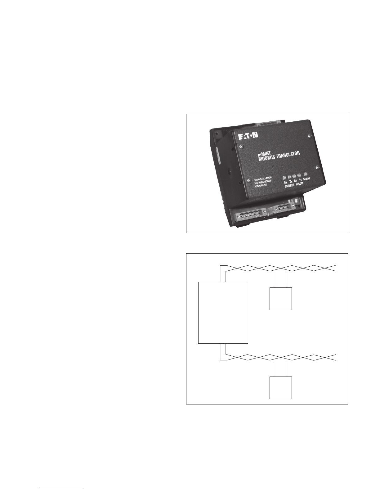
Figure 2. mMINT in a communications network ................2
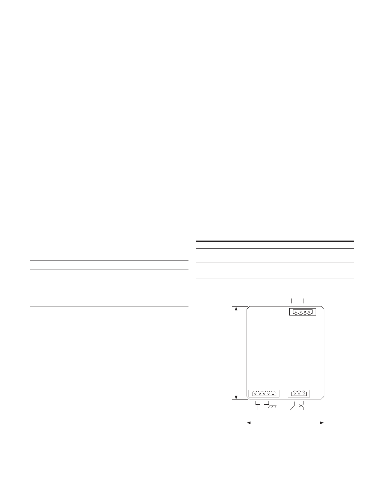
Figure 3. Connections ....................................3
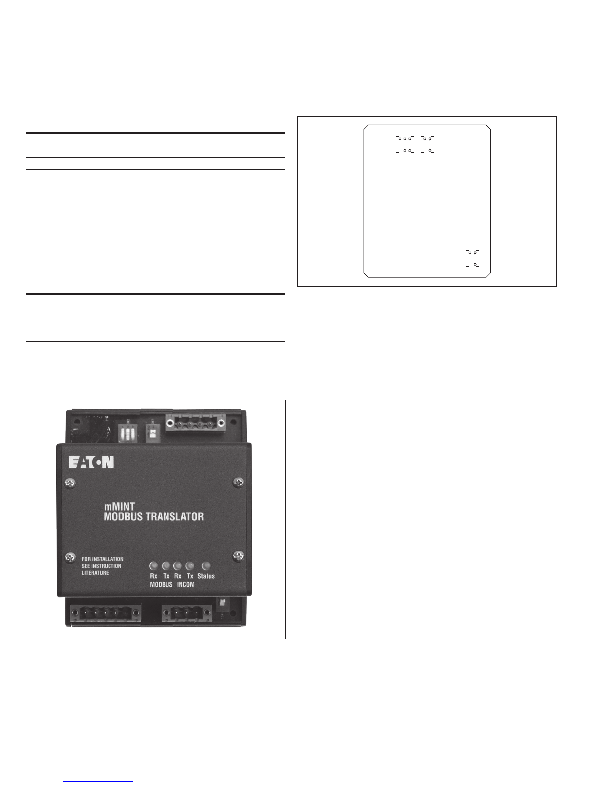
Figure 4. Indicators ......................................4
Figure 5. Switches .......................................4
Figure 6. Pass-through to INCOM product query data format .....6
Figure 7. Pass-through to INCOM product response data format ...7
Figure 8. Control to INCOM product data format ...............7
Figure 9. 4-register energy data format ......................8
List of tables
Description Page
Table 1. Power connector pin outs ..........................3
Table 2. INCOM connector pin outs .........................4
Table 3. Modbus RS-485 connector pin outs ..................4
Table 4. RS-485 baud rate switches (normal) ..................5
Table 5. RS-485 baud rate switches (diagnostics) ..............5
Table 6. Diagnostic sub-function numbers ....................8
Table 7. Troubleshooting guide .............................9
Table 8. Modbus register map (in register number order) .......10
Table 9. Modbus register map (in functional order) ............14
Table 10. Primary status code definitions ....................17
Table 11. Secondar y status code definitions .................. 17
Table 12. Cause-of-status code definitions ...................17
Table 13. Control ‘Slave Action Number’ definitions ...........18
Table 14. mMINT configuration registers ....................19
Section 1: General description
The mMINT (ModbusT Master INCOM network translator) module,
as seen in Figure 1, is an Eaton accessory product that will provide
communication between a Modbus RTU network and an INCOME
(INdustrial COMmunications) network (see Figure 2). This module is
transparent to the Modbus network. It communicates to a master on
the Modbus network using the Modbus RTU (remote terminal unit)
protocol. It communicates to slave devices on the INCOM network
using the PowerNet protocol. The catalog number of this product
is MMINT.
Figure 1. The mMINT module
Modbus RTU serial network
(Slave)
Modbus
mMINT
(Master)
INCOM network
Figure 2. mMINT in a communications network
Modbus master
INCOM slaves
2
EATON www.eaton.com
Page 3
mMINT—Modbus translator module—
installation and use
Section 2: Features
The mMINT module is a slave device on the Modbus network and
as such requires a master that will exchange register objects with
the mMINT module.
•
Handles generic pass-through commands
(Modbus/INCOM/Modbus)
•
Capable of passing Modbus register objects from Eaton’s
existing products and newer Plug-n-Play products to a Modbus
RTU master
•
Data in IEEET Floating Point format and fixed point.
•
Modbus RTU communications data transfer rates of 1200, 9600,
or 19200 baud with one start bit, eight data bits, no parity, and
either one or two stop bits
•
Up to 32 products connected to INCOM network port
(246 unique addresses maximum)
•
Flashing Status LED to indicate an active module
•
LED indicators for INCOM transmit and receive
communications exchanges
•
LED indicators for Modbus RS-485 transmit and receive
communications exchanges
•
Input power for the module from either 120 Vac or 24 to 125 Vdc
•
DIN rail mount package
•
0 °C to 60 °C ambient operation
Section 3: Installation
The mMINT module is designed to be installed, operated, and
maintained by adequately trained personnel. These instructions
do not cover all of the details or variations of the equipment
for its storage, delivery, installation, checkout, safe operation,
or maintenance.
m WARNING
DO NOT ATTEMPT TO INSTALL OR PERFORM MAINTENANCE ON
EQUIPMENT WHILE IT IS ENERGIZED. DEATH OR SEVERE PERSONAL
INJURY CAN RESULT FROM CONTACT WITH ENERGIZED EQUIPMENT.
ALWAYS VERIFY THAT NO VOLTAGE IS PRESENT BEFORE PROCEEDING.
ALWAYS FOLLOW SAFETY PROCEDURES. EATON IS NOT LIABLE FOR THE
MISAPPLICATION OR MISINSTALLATION OF ITS PRODUCTS.
Instructional Leaet IL66A7508H09
Effective October 2016
•
Make sure that there is twisted-pair wire that is recommended for
PowerNet network use. Use shielded twisted-pair wire to connect
each slave to the INCOM network, daisy-chain style. The polarity
of the twisted pair is not important.
Modbus RS-485 network
The following simplified rules apply to a given system consisting of
a cable link between master and slave devices (see Figure 2). For
more complex configurations, please refer to standard Modbus RTU
wiring specification rules for the RS-485 network.
•
The recommended Modbus cable has twisted-pair wires
(24 AWG stranded 7x32 conductors with PVC insulation)
having an aluminum/mylar foil shield with drain wire
•
The maximum system capacity is 4000 feet of communications
cable and 247 devices on the Modbus RTU network
•
Make sure that there is twisted-pair wire that is recommended
for Modbus RTU network use. Use shielded twisted-pair wire
to connect each slave to the Modbus RTU network, daisy-chain
style. The polarity of the twisted pair is critically important.
Section 4: mMINT module connections
Refer to Figure 3 and the following three pin out tables for
installation specifics.
Power connections
Power connector: Module power uses a 5-pin input connector
(see Figure 3). Power requirements are 120 Vac, 60 Hz or
24–125 Vdc. Refer to Table 1.
Table 1. Power connector pin outs
Pin number Input power
1 Chassis ground
2 and 3 Vac neutral/Vdc common
4 and 5 Vac line/24 –125 Vdc+
RS-485
Modbus
A B
COM SHD
If you have any questions or need further information or instructions,
please contact your local Eaton representative or the Customer
Support Center at 877-ETN-CARE (877-386-2273).
Module mounting
When mounting the mMINT, verify that an 11H x 28W mm DIN rail
is used and that it is within an enclosed space.
Simplified wiring rules
INCOM network
The following simplified rules apply to a given system consisting of
a single daisy-chained main cable link between master and slave
devices (see Figure 2). For more complex considerations, including
star configurations, please refer to the wiring specification T.D. 17513.
•
Recommended INCOM cable styles are Belden 9463 or
C-H style 2A957805G01
•
The maximum system capacity is 10,000 feet of communications
cable and 32 slave devices on the INCOM network under
the mMINT
•
Non-terminated taps, up to 200 feet in length, off the main link
are permitted, but add to the total cable length
4.25
(108.0)
Figure 3. Connections
J1
24–125 Vdc
120 Vac
EATON www.eaton.com
J3
J2
Shield INCOM
3.54
(89.9)
3
Page 4
Instructional Leaet IL66A7508H09
Effective October 2016
mMINT—Modbus translator module—
installation and use
INCOM connections
INCOM connector: This 3-pin connector provides the interface to
the INCOM network. Refer to Table 2.
Table 2. INCOM connector pin outs
Pin number Input/output signal
1 INCOM carrier network
2 INCOM carrier network
3 Shield
Connect shield wire to ground at master device end only.
Interconnect shielding where devices are daisy chained.
Modbus connections
Modbus RS-485 Connector: This 4-pin connector provides the
interface to the Modbus RTU network. The polarity is “critically”
important. Refer to Table 3.
Table 3. Modbus RS-485 connector pin outs
Pin number Input/output signal
1 RS-485 Network-A (non-inverting)
2 RS-4 85 Net work-B (inverting)
3 Common
4 Shield
RS-485 Network-A is the non-inverting differential connection for the
Modbus RTU network. RS-485 Network-B is the inverting differential
connection for the Modbus RTU network.
Section 5: Switches and indicator LEDs
Refer to Figure 4 to locate the Status LED for the mMINT module.
Figure 5 shows the location of the configuration switches.
SW2 SW3
Closed
Open
SW1
Figure 5. Switches
Modbus RS-485 network Rx LED (green)
The LED will be lighted whenever the module is receiving from the
Modbus RTU network.
Modbus RS-485 network Tx LED (green)
The LED will be lighted whenever the module is transmitting on the
Modbus RTU network.
INCOM network Rx LED (green)
The LED will be lighted whenever the module is receiving from the
INCOM network.
Figure 4. Indicators
INCOM network Tx LED (green)
The LED will be lighted whenever the module is transmitting on the
INCOM network.
Status LED (green)
This indicator will be flashing whenever the module is powered up
and the microcontroller is executing instructions. The flashing rate is
approximately 1 second ON / 1 second OFF. However, detection of
a communications error on either the Modbus or INCOM network
will result in an increased flashing rate approximately 1/2 second ON
/ 1/2 second OFF. The rate will return to normal when the network’s
diagnostic reset subfunction (clear UART or slave counters,
respectively) is processed by the mMINT. See Section 6 and Table 6.
INCOM 100 ohms termination DIP switch (SW1)
This switch should be moved to the ON position only when it is the
last unit in a chain of units or if it is a single unit.
Modbus RS-485 baud rate DIP switch (SW2)
To configure the data transfer rate for the Modbus RTU network,
three switches in DIP switch SW2 should be moved to either the
CLOSE or the OPEN position based on the rate required. Refer to
Table 4. SW2-1 is for mMINT diagnostics.
4
EATON www.eaton.com
Page 5

mMINT—Modbus translator module—
installation and use
Instructional Leaet IL66A7508H09
Effective October 2016
Table 4. RS-485 baud rate switches (normal)
Baud SW 2-1 SW2-2 SW2-3
1200 X CLOSE CLOSE
9600 X OPEN CLOSE
19200 X CLOSE OPEN
Unique mMINT address (SW2)
The mMINT can be assigned address 247 and 248. For the mMINT
to respond to a diagnostic query related to address 247 or 248 on
the Modbus network, move DIP switch SW2-1 to the OPEN position.
Refer to Table 5. Normally, this switch is in the CLOSE position.
Table 5. RS-485 baud rate switches (diagnostics)
Baud SW 2-1 SW2-2 SW2-3
Addr. 247 or 248 OPEN X X
Normal CLOSE X X
Modbus 121 ohm termination DIP switch (SW3)
This switch should be moved to the ON position only when it is the
last unit in a chain of units or if it is a single unit.
Section 6: Network communication protocols
The lower INCOM communication network for the mMINT is
based on a master-slave protocol. The mMINT is a master on the
INCOM network.
In order to satisfy the mMINT communications needs, please see
Reference Materials:
IL17384—Part A: INCOM Communications Standard, Eaton.
Specific product profiles are located in the other Part sections.
http://www.eaton.com, then search on 17384.
“Modicon Modbus Protocol”
http://www.modicon.com/techpubs/toc7.html
Overview
The contents of Modbus registers are INCOM product objects
—phase A current). The mMINT ensures that unique objects
(e.g., I
A
reside in identical registers independent of INCOM product.
Consequently, for all INCOM products there is a single register
map of objects. See Table 8 or Table 9.
INCOM objects occupy two registers except for certain energy—
real and reactive—objects. These energy objects occupy four
registers. The mMINT can support a maximum of 122 registers
within a single Modbus transaction.
The mMINT is transparent to the Modbus master and responds
to every address of INCOM products attached to it. In its default
configured state, INCOM product addresses are Modbus network
addresses. The mMINT can be configured to route the Modbus
address to a different INCOM product address or an INCOM
sub-network product address. See Section 6.
An upgrade has been incorporated to allow the mMINT to
communicate with Modbus masters that can only access to
register 9999. Registers previously assigned above 9999 have
been assigned dual access, both at the original register (to provide
compatibility) and at a new register assignment below 9999.
The format is given as low/high register numbers followed by
/high16 Modbus register addresses), for example:
(low
16
4xxxx/4yyyyy (XXXX+1
Only the RTU communications mode is recognized by the mMINT.
/YYYY+116). See Table 14.
16
Function codes
The mMINT responds to a limited number of Modbus function
codes. These are function codes 03, 04, 08, and 16 (10
).
16
Block of registers
A block of registers (from the register column of Table 8 or Table 9)
can be established for each INCOM product attached to a mMINT.
Function code 16 (10
the block of registers. The block assignments are stored beginning at
register 41001/420481 (03E8
address is assigned within the block of registers. For example,
although object I
), only register address (120216) is loaded into the block
(1203
16
of assignment registers. Verification of this block of assignment
) is used to load the object assignments for
16
/500016).Only the first object register
16
occupies registers 404611 (120216) and 404612
A
registers can be read from the mMINT by a read function code 03
or 04 from these 41001/420481 (03E8
/500016) registers.
16
Data pertaining to the objects configured in the block of assignment
registers is mapped into registers starting at 41201/420737
/510016) and continuing in successive order for each object
(04B0
16
assigned. The number of objects and their placement order in this
data block of registers is dependent on the configuration of the block
of assignment registers. The total number of data block of registers
is limited to 100.
ote:N An object can occupy one, two, or four registers.
The data can be obtained from the data block of registers by a read
function code 03 or 04. The address of the starting object must be
aligned with a starting address of an object within the data block
of registers. The number of registers to obtain must align with an
ending address of an object within the data block of registers.
Register access configurations
Non-volatile register 42001/425345 (07D016/630016) is used to
configure the mMINT to respond to a group of data objects, of
which some objects are invalid within that group. When non-zero
(factory default value), any attempt to access a group of data objects
that contain an invalid object will result in an illegal data object
exception code 02. See Section 6.
When register 42001/425345 (07D0
the mMINT will respond to a group of objects with data contained in
/630016) is set to zero, however,
16
the valid objects of the group along with an illegal
value, if available else 0000
Non-volatile register 42002/425346 (07D1
configure 32-bit IEEE floating point word order. When non-zero
, data contained in the invalid objects.
16
/630116) is used to
16
(factory default), the floating point low order word is first in the
Modbus register space.
When register 42002/425346 (07D1
the floating point high order word is first in the Modbus register
/630116) is set to zero, however,
16
space.
Non-volatile register 42002/425347 (07D1
configure 32-bit fixed point and 64-bit energy word order. When
/630216) is used to
16
non-zero (factory default), the fixed point and energy low order
word is first in the Modbus register space.
When register 42003/425347 (07D2
the fixed point and energy high order word is first in the Modbus
/630216) is set to zero, however,
16
register space.
Registers not containing a 32-bit or 64-bit format, such as Status and
Product ID objects, pass through registers, INCOM control registers,
and INCOM routing address configuration registers, are not effected
by the word order configuration registers.
Configuring any or all registers 42001/425345 through 42003/425347
/630016 through 07D216/630216) is accomplished using a write
(07D0
16
function code 16 (10
ote:N mMINT SW2-1 must be properly set. See Section 5 and Table 5.
) to mMINT diagnostic address 247 or 248.
16
EATON www.eaton.com
5
Page 6

Instructional Leaet IL66A7508H09
Effective October 2016
INCOM routing address configurations
Non-volatile registers 42101 (083416) through 42592 (0A1F16) are
used to configure the 246 Modbus-to-INCOM Routing Address
registers. Two consecutive INCOM routing registers correspond
to each Modbus address. The first register provides routing to an
INCOM main network address while the second (first+1) register
provides routing to an INCOM sub-network address. Registers 42101
and 42102 correspond to Modbus address 1, registers 42103 and
42104 correspond to Modbus address 2, etc.
Valid INCOM addresses range from 0001
INCOM addresses are 0000
invalid (default) setting in the INCOM main network address register
or Yxxx16, where Y is non-zero. Any
16
will cause the mMINT to access the INCOM product with the
Modbus network address. A valid INCOM main network address
register with an invalid INCOM sub-network address register will
route the Modbus network address to the INCOM product at
the configured main network address. Both a valid INCOM main
network address register and INCOM sub-network address register
will route the Modbus network address to an INCOM product at the
configured sub-network address accessed through a sub-network
master addressed at the INCOM main network address.
All INCOM Routing Address Configuration registers can be reset
to their default state using the Diagnostics function code 08,
sub-function 30 (1E
). See Section 6 and Table 6.
16
Command/data pass-through
A feature of the mMINT is its capability to pass INCOM commands/
data directly through to any of 32 attached INCOM products. Thus,
with access to IL 17384, Parts A through F, every INCOM product
object and capability is available to the Modbus master.
When passing a command or data through to an INCOM product,
the mMINT acts as a dumb slave. Without modification, it passes
the command or data through to the INCOM product.
In the event the product responds, the mMINT saves the response
until the Modbus master queries for that response. The response
data remains in the mMINT until another pass-through command is
issued to an attached product or a mMINT power cycle occurs. The
mMINT makes no modification to or interpretation of the product
response data.
The Modbus master writes the INCOM product command/data
using function code 16 (10
/600016).
(0A28
16
) beginning at register 42601/424577
16
The data format for passing information through the mMINT to an
INCOM product is given in Figure 8.
The Modbus master reads the INCOM product response to a
pass-through query using either function code 03 or 04 beginning
at register 42701/424833 (0A8C
/610016).
16
The number of points (registers) of the read query is 2*nn—
where nn is the number of INCOM messages in the response.
The format of the data acquired by the mMINT from the passthrough INCOM product query’s response is given in Figure 7.
ote:N Each INCOM response message contains a status byte that indicates
its validity.
through 0FFF16. Invalid
16
mMINT—Modbus translator module—
installation and use
Register 42601/424577 (0A2816/600016)
15 14 13 12 11 10 9 8 7 6 5 4 3 2 1 0
nn = Number of Response
Msgs from INCOM Product
0 = Reserved
0 = Data Msg/1 = Control Msg
INCOM Msg Control Byte
INCOM Msg Byte 0
Register 42602/424578 (0A29
15 14 13 12 11 10 9 8 7 6 5 4 3 2 1 0
INCOM Msg Byte 2
Figure 6. Pass-through to INCOM product query data format
Control of INCOM product
Since a control error could result in unwanted actions initiated by
an INCOM device, the mMINT requires a specific protocol by the
Modbus master in order to perform control related functions within
the INCOM product.
A set of registers is reserved for the control protocol. They begin
at register 42901/425089 (0B54
42903/425091 (0B56
with a ‘slave action number’ and its 1’s complement using function
code 16 (10
product dependent, are listed in Table 13. The format of the data
). The current ‘slave action numbers’, their support being
16
/620216). These three registers are written
16
is shown in Figure 8. These three registers, and only these three
registers, must be written in one Modbus transaction.
If the ‘slave action number’ and its 1’s complement are valid, the
mMINT issues the ‘slave action’ control command onto the INCOM
network. If the slave action request is successfully acknowledged
by the INCOM product, the mMINT returns a normal function code
) response to the Modbus master. The Modbus master may
16 (10
16
further determine if the INCOM product completed the slave action
function successfully by interrogating the product, for example, by
reading its status.
If the INCOM product does not acknowledge the slave action
request, the mMINT returns an exception code 04. If the ‘slave
action number’ and its 1’s complement are invalid, the mMINT
responds to the Modbus master with a data value illegal exception
code 03. See Section 6.
/600116)
16
INCOM Msg Byte 1
/620016) and extend through
16
6
EATON www.eaton.com
Page 7
mMINT—Modbus translator module—
installation and use
Instructional Leaet IL66A7508H09
Effective October 2016
Register 42701/424833 (0A8C16/610016)
15 14 13 12 11 10 9 8 7 6 5 4 3 2 1 0
1 = Timeout on INCOM
1 = Overrun Error
1 = BCH Error
0 = Data Msg/1 = Control Msg
Status Byte of INCOM
Response Msg 0
Byte 0 of INCOM Response Msg 0
Register 42702/424834 (0A8D
15 14 13 12 11 10 9 8 7 6 5 4 3 2 1 0
Byte 2 of INCOM
Response Msg 0
Register 42703/424835 (0A8E
15 14 13 12 11 10 9 8 7 6 5 4 3 2 1 0
Byte 0 of INCOM
Response Msg 1
Register 42704/424836 (0A8F
15 14 13 12 11 10 9 8 7 6 5 4 3 2 1 0
Byte 2 of INCOM
Response Msg 1
Register 42701/424833 + (2 * nn))
15 14 13 12 11 10 9 8 7 6 5 4 3 2 1 0
Byte 0 of INCOM
Response Msg nn
Register 42702/424834 + (2 * nn))
15 14 13 12 11 10 9 8 7 6 5 4 3 2 1 0
Byte 2 of INCOM
Response Msg nn
/6 10116)
16
Byte 1 of INCOM
Response Msg 0
/610216)
16
Status Byte of INCOM
Response Msg 1
/610316)
16
Byte 1 of INCOM
Response Msg 1
Status Byte of INCOM
Response Msg nn
Byte 1 of INCOM
Response Msg nn
0 = Reserved
Register 42901/425089 (0B5416/620016)
15 14 13 12 11 10 9 8 7 6 5 4 3 2 1 0
Slave Action Byte 0
Slave Action Byte 1
Register 42902/425090 (0B55
15 14 13 12 11 10 9 8 7 6 5 4 3 2 1 0
1’s Complement of Slave Action Byte 0
Register 42903/425091 (0B56
15 14 13 12 11 10 9 8 7 6 5 4 3 2 1 0
1’s Complement of Slave Action Byte 2
/620116)
16
Slave Action Byte 2
/620216)
16
1’s Complement of
Slave Action Byte 1
Figure 8. Control to INCOM product data format
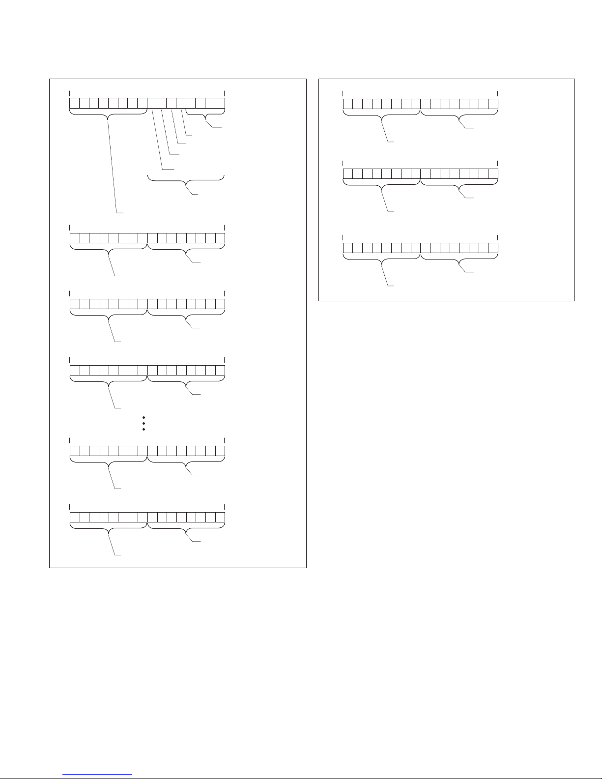
Energy format
Energy objects in the mMINT are supported in 2-register fixed point
object format and a 4-register power/mantissa format. These objects
do not support IEEE floating point format.
The 2-register format is presented in units of Kwatthours and
is valid for INCOM products reporting energy in watthours or
Kwatthours only. Products reporting in units greater than Kwatthours
(e.g., Mwatthours) could not guarantee consistent Kwatthour
resolution up to and through their rollover values.
All products reporting energy (independent of energy units) support
the energy objects occupying four registers—register 3 through
register 0. Register 3 is the high order register and register 0 is the
low order register.
Register 3 high byte contains a value corresponding to Engineering
Units (power of 10 signed exponent). Register 3 low byte contains a
Mantissa Multiplier value (power of 2 signed exponent).
Register 2 through register 0 contains a 48-bit energy mantissa in
units of watthours. Net and total energy objects are signed values.
All other energy objects are unsigned values.
The data format of these four registers is given in Figure 9.
Energy = 2
Mantissa Multiplier
x (48-bit energy value) x 10
Engineering Units
.
Figure 7. Pass-through to INCOM product response
data format
EATON www.eaton.com
7
Page 8

Instructional Leaet IL66A7508H09
Effective October 2016
Energy Register 0
15 14 13 12 11 10 9 8 7 6 5 4 3 2 1 0
Byte 1 of Mantissa
Energy Register 1
15 14 13 12 11 10 9 8 7 6 5 4 3 2 1 0
Byte 3 of Mantissa
Energy Register 2
15 14 13 12 11 10 9 8 7 6 5 4 3 2 1 0
Byte 5 of Mantissa
Energy Register 3
15 14 13 12 11 10 9 8 7 6 5 4 3 2 1 0
Engineering Units
Energy = 2
Mantissa Multiplier
x Mantissa x 10
Engineering Units
Byte 0 of Mantissa
Byte 2 of Mantissa
Byte 4 of Mantissa
Mantissa Multiplier
mMINT—Modbus translator module—
installation and use
Table 6. Diagnostic sub-function numbers
Sub-function
Number (decimal) Name In the query use
0 echo query mMINT or INCOM addr
1 restart communications mMINT or INCOM addr
4 force listen mMINT or INCOM addr
10 clear slave counters mMINT or INCOM addr
11 UART bus message count mMINT or INCOM addr
12 UART communication error count mMINT or INCOM addr
13 slave exception error count mMINT or INCOM addr
14 slave message count mMINT or INCOM addr
15 slave no response count mMINT or INCOM addr
16 slave NAK count mMINT or INCOM addr
17 slave busy count mMINT or INCOM addr
18 UART over run error count mMINT or INCOM addr
20 clear UART counters mMINT or INCOM addr
21 slave INCOM BCH error count INCOM device addr
22 slave INCOM over run count INCOM device addr
23 UART framing error count mMINT or INCOM addr
24 UART noise error count mMINT or INCOM addr
25 UART parit y error count mMINT or INCOM addr
26 mMINT firmware version & rev mMINT addr
27 mMINT firmware month & day mMINT addr
28 mMINT firmware year mMINT addr
29 remove INCOM device(s) mMINT or INCOM addr
30 reset INCOM routing addresses mMINT addr
Figure 9. 4-register energy data format
Supported diagnostic sub-functions
It is possible to obtain diagnostics from the mMINT or an attached
INCOM product using function code 08. See Table 6. A single
register is used for each UART counter within the mMINT. Each
INCOM device and the mMINT contain a unique slave counter.
To use mMINT address 247 or 248 in the diagnostic query, SW2-1
must be properly set. See Section 5 and Table 5.
Exception codes
Under certain circumstances, the mMINT will return an
exception code.
If the function in the query is not supported by the mMINT,
exception code 01 is returned in the response.
If the data (object) register is illegal, exception code 02 is returned in
the response.
If the data value in the query is illegal, exception code 03 is returned.
If the slave INCOM product fails (usually a timeout), exception code
04 is returned.
In certain circumstances, an exception code 05 (ACK) is returned.
If the mMINT cannot perform the requested function, exception
code 07 (NAK) is returned.
If only a partial register is used in the query, exception code 84
is returned.
8
EATON www.eaton.com
Page 9

mMINT—Modbus translator module—
installation and use
Instructional Leaet IL66A7508H09
Effective October 2016
Section 7: Troubleshooting
The most common issues experienced with the installation of an
mMINT module are addressed below.
If you have any questions or need further information or instructions,
please contact your local Eaton representative or the Customer
Support Center at 877-ETN-CARE (877-386-2273).
Table 7. Troubleshooting guide
Symptom Possible solution(s)
Status LED not flashing Verify proper input power to module connector
Modbus Tx LED is flashing, but the
module does not respond to master
command requests
INCOM Tx LED is flashing, but the
module does not respond to master
command requests
Removing an INCOM product and
assigning its INCOM (Modbus)
address to another (different) INCOM
product, and exception codes are
received from the INCOM product
Verify communication cable is connected
correctly from the master to the module
(A, B, +, –)
Verify the data transfer rate is correctly set
using baud rate switch (SW2)
Verify communication cable is connected
correctly from the slave to the module
Verify the product is set up for 9600 baud
Verify that the termination switch (SW1)
is set to ON at the last module
Disconnect the reassigned product from the
INCOM network
Verify that the Modbus Master has sent at
least two requests to the address of the
product that was just disconnected
Connect the reassigned INCOM product
Appendix A
otes:N
1. Modbus is a registered trademark of Schneider Electric.
2. mMINT modules use DIN rail mounting.
3. Control voltage is 120 Vac +/–20% or 24–125 Vdc.
4. Connectors are plug-in types from Phoenix contact.
5. Terminal Types (supplied with module) are 3-point, 4-point, and
5-point Phoenix contact.
• MVSTBR2,5/3-STF-5,08 (Order No. 1835106)
• MVSTBR2,5/4-STF-5,08 (Order No. 1835119)
• MVSTBR2,5/5-STF-5,08 (Order No. 1835122)
6. INCOM communications cable is Eaton C-H style 2A957805G01
or Belden style 9463.
7. Set up switch SW1 to insert 100 ohm terminating resistor on
last module in the INCOM network.
8. Set up switch SW2 to select data transfer rate on the
Modbus network.
9. Set up switch SW3 to insert 121 ohm terminating resistor on
last module in the Modbus network.
10. Power wiring is any approved 300 V, 10 A, 30–12 AWG
(stranded or solid).
11. The register map for INCOM products is shown in register
number order in Table 8 and functional order in Table 9.
Numeric entries indicated with an asterisk (*) have specific
definitions dependent upon the particular INCOM product.
These tables include only a partial list of applicable INCOM
products; however, it contains a complete list of the INCOM
objects directly supported by the mMINT. Due to the mMINT
pass-through feature, all INCOM product objects are accessible
by a Modbus master.
12. The primary and secondary codes are mapped to the high
and low bytes, respectively, of registers 404609 (1200
and 406145 (1800
Table 10. The secondary status codes are shown in Table 11.
). The primary status codes are shown in
16
The cause-of-status codes are mapped to registers 404610
) and 406146 (180116). The cause-of-status codes are
(1201
16
shown in Table 12.
13. Catalog number is MMINT.
)
16
EATON www.eaton.com
9
Page 10

Instructional Leaet IL66A7508H09
Effective October 2016
Table 8. Modbus register map (in register number order)
Objects (complete list)
Register number Modbus address
mMINT—Modbus translator module—
installation and use
INCOM products (partial list)
Fixed
point
(FP)
(Hex)
Name Numeric
Status
cause
primary 404609 or 406145 hi byte 1200 or 1800 hi byte
secondary 404609 or 4 06145 lo byte 1200 or 1800 lo byte
Units
IEEE
float
Fixed
point
(FP)
IEEE
float
(Hex)
cause 404610 or 406146 1201 or 1801
Current I
L-L
voltage
L-N v olt a ge V
N-G
voltage
Peak
current
A
I
B
I
C
I
G
I
N
I
Avg
V
AB
V
BC
V
CA
V
LLavg
AN
V
BN
V
CN
V
LN
V
NG
peak IA demand A 404641 406177 122 0 182 0 10
peak IB demand A 404643 406179 1222 1822 10
A 404611 406147 1202 1802 10
A 404613 406149 120 4 180 4 10
A 404615 40 6151 1206 1806 10
A 404617 406153 1208 1808 10
A 404619 40 615 5 120A 180 A 10
A avg 404621 4 06157 120C 180C 10
V 404623 406159 120E 180E 10
V 404625 406161 1210 1810 10
V 404627 406163 1212 1812 10
V avg 404629 40616 5 1214 1814 10
V 404631 40616 7 1216 1816 10
V 404633 40616 9 1218 1818 10
V 404635 406171 121A 181A 10
V avg 404637 406173 121C 181C 10
V 404639 40617 5 121E 181E 10
peak IC demand A 404645 406181 12 24 18 24 10
peak IG demand A 404647 40 618 3 1226 1826 10
peak IN demand A 404649 406185 122 8 182 8 10
Power real three-phase
W 404651 406187 122 A 18 2A 1
(power)
reactive
var 404653 4 06189 122C 182C 1
three-phase
apparent
VA 404655 40 6191 122E 182E 1
three-phase
Power
factor
displacement
three-phase
pf 404657 4 06193 1230 18 30 100
apparent pf 404659 406195 1232 1832 100
Frequency freq Hz 404661 40 619 7 1234 18 34 10
K-factor K-factor 404663 40 619 9 1236 1836 1
THD factor THD factor 404665 406201 123 8 1838 1
ote:N All objects are two registers in length unless specified otherwise.
FP scale factor
IQ 200
DP-4000
IQ Analyzer
IQ Data
IQ Data Plus II
DigitripE OPTIM 55 0
Digit rip OPTIM 750
Digit rip OPTIM 1050
Digitrip 810
Digitrip 910
Digitrip 520MC
Digitrip 1150
IQ Transfer II
n n n n n n n n n n n n n n n n
n n n n n n n n n n n n n n n n
n n n n n n n n n n n n n n n n
n n n n n n n n n n n n n n n
n n n n n n n n n n n n n n n
n n n n n n n n n n n n n n n
n n n n n n n n n n n
n n n n n n n n n
n n n
n n n n n n n n
n n n n n n n n
n n n n n n n n
n n
n n n n n n n
n n n n n n n
n n n n n n n
n n
n
n n n n n n n n n
n n n n n n n n n
n n n n n n n n n
n n n n
n n n
n n n n n n n n n
n n n n n n
n n n n n
n n n n
n n n n n n n n n
n n n n n n n
n
n
MP-3000
Digitrip 3000T
FP-5000
10
EATON www.eaton.com
Page 11

mMINT—Modbus translator module—
installation and use
Table 8. Modbus register map (in register number order) (continued)
Objects (complete list)
Register number Modbus address
Instructional Leaet IL66A7508H09
Effective October 2016
INCOM products (partial list)
Fixed
point
(FP)
(Hex)
Name Numeric
Units
IEEE
float
Fixed
point
(FP)
IEEE
float
(Hex)
Power A ph W 404667 406203 123 A 18 3A 1
B ph W 404669 406205 123C 183C 1
C ph W 404671 406207 123E 183E 1
reactive A ph var 404673 406209 124 0 1840 1
reactive B ph var 404675 4 06211 1242 1842 1
reactive C ph var 404677 406213 1244 184 4 1
apparent A ph VA 404679 4 06215 1246 1846 1
apparent B ph VA 404681 406 217 124 8 184 8 1
apparent C ph VA 404683 406 219 124 A 184 A 1
Power
factor
displacement A ph pf 404685 406221 124C 184C 100
displacement B ph pf 404687 406223 124 E 184 E 10 0
displacement C ph pf 404689 406225 1250 18 50 100
apparent A ph pf 404691 406227 12 52 1852 100
apparent B ph pf 404693 406229 1254 185 4 10 0
apparent C ph pf 404695 406231 1256 1856 100
Power peak demand W 404697 406233 125 8 1858 1
Source 1 V
AB
V
BC
V
CA
V 404699 406235 125 A 18 5A 10
V 404701 406237 125 C 185C 10
V 404703 406239 125 E 18 5E 10
freq Hz 404705 406241 12 60 186 0 10
Source 2 V
AB
V
BC
V
CA
V 404707 406243 1262 1862 10
V 404709 406245 1264 186 4 10
V 4 047 11 406247 1266 1866 10
freq Hz 404713 406249 1268 18 68 10
Power power (real
W 404715 406251 126A 186A 1
three-phase)
Power
pf (*) pf 4 04717 406253 126C 186C 100
factor
Product ID prod ID 404719 or 406255 126E or 186E
FP scale Factor
IQ 200
DP-4000
IQ Analyzer
IQ Data
IQ Data Plus II
Digit rip OPTIM 550
Digit rip OPTIM 750
Digit rip OPTIM 1050
Digitrip 810
Digitrip 910
Digitrip 520MC
Digitrip 1150
IQ Transfer II
n n
n n
n n
n n
n n
n n
n n
n n
n n
n n
n n
n n
n n
n n
n n
n n n n n n n n n
n
n
n
n
n
n
n
n
n n n n n n n n n
n n n n n n n n n
n n n n n n n n n n n n n n n n
MP-3000
Digitrip 3000
FP-5000
ote:N All objects are two registers in length unless specified otherwise.
EATON www.eaton.com
11
Page 12

Instructional Leaet IL66A7508H09
Effective October 2016
Table 8. Modbus register map (in register number order) (continued)
Objects (complete list)
Register number Modbus address
mMINT—Modbus translator module—
installation and use
INCOM products (partial list)
Fixed
point
(FP)
(Hex)
Name Numeric
Units
IEEE
float
Fixed
point
(FP)
IEEE
float
(Hex)
Frequency freq Hz 404721 406257 1270 18 70 100
(K) Energy forward kWh N/A 406259 N/A 187 2 1
reverse kWh N/A 406261 N /A 1874 1
total (*) kWh N/A 406263 N/A 1876 1
Reactive (K)
energy
lead kvarhW N /A 406265 N/A 1878 1
lag kvarhW N/A 406267 N /A 187A 1
net kvarhW N/A 406269 N/A 187C 1
(K) Energy apparent kVAh N/A 406271 N/A 187E 1
Motor phase
% 404737 406273 128 0 18 80 10 0
unbalance
thermal
% 404739 406275 128 2 1882 100
capacity
Temperature motor
°C 404741 406277 1284 188 4 1
winding 1
motor
°C 404743 406279 128 6 1886 1
winding 2
motor
°C 404745 406281 1288 1888 1
winding 3
motor
°C 404747 406283 128A 188A 1
winding 4
motor
°C 404749 406285 128C 188C 1
winding 5
motor
°C 404751 406287 128E 188E 1
winding 6
motor
°C 404753 406289 129 0 1890 1
bearing 1
motor
°C 404755 406291 1292 1892 1
bearing 2
load
°C 404757 406293 129 4 18 94 1
bearing 1
load
°C 404759 406295 1296 189 6 1
bearing 2
auxiliary °C 404761 406297 1298 1898 1
device
temperature
°C 404763 406299 129 A 18 9A 1
404765 406301 129 C 189C
404767 406303 129 E 189E
Energy
(4 reg objects)
forward Wh N/A 406305 N /A 18A0 1
reverse Wh N/A 406309 N/A 18 A4 1
total (*) Wh N/A 406313 N/A 18A8 1
Reactive
energy
(4 reg objects)
lead varh N/A 406317 N/A 18AC 1
lag varh N/A 406321 N/A 18 B0 1
net varh N/A 406325 N/A 18B4 1
Energy (4 reg) apparent VAh N/A 406329 N/A 18B8 1
(4 reg) N/A 406333 N/A 18BC
ote:N All objects are two registers in length unless specified otherwise.
FP scale factor
IQ 200
DP-4000
IQ Analyzer
IQ Data
IQ Data Plus II
Digit rip OPTIM 550
Digit rip OPTIM 750
Digit rip OPTIM 1050
Digitrip 810
Digitrip 910
Digitrip 520MC
Digitrip 1150
IQ Transfer II
n n n n n n n
n n n n n n n n
n n n n n n n n
n n n n n n n n n
n n n n
n n n n
n n n n
n n n n n
n n n n n n n n
n n n n n n n n
n n n n n n n n n
n n n n
n n n n
n n n n
n n n n n
n
n
n
n
n
n
n
n
n
n
n
n
n
MP-3000
Digitrip 3000
FP-5000
12
EATON www.eaton.com
Page 13

mMINT—Modbus translator module—
installation and use
Table 8. Modbus register map (in register number order) (continued)
Objects (complete list)
Register number Modbus address
Instructional Leaet IL66A7508H09
Effective October 2016
INCOM products (partial list)
Name Numeric
Network
voltage
A ph V 404801 406337 12C0 18C 0 10
B ph V 404803 406339 12C2 18 C2 10
Units
IEEE
float
Fixed
point
(FP)
IEEE
float
(Hex)
C ph V 404805 406341 12C4 18C4 10
Transformer
voltage
A ph V 404807 406343 12C 6 18C6 10
B ph V 404809 406345 12 C8 18C8 10
C ph V 4 04811 406347 12C A 18CA 10
Phasing
voltage
A ph V 40 4813 406349 12C C 18CC 10
B ph V 4 048 15 406351 12C E 18CE 10
C ph V 4 04817 406353 12D0 18D0 10
A ph direct V 40 4819 406355 12D 2 18D2 10
A ph
V 404821 406357 12D4 18D4 10
quadrature
B ph direct V 404823 406359 12D6 18D 6 10
B ph
V 404825 406361 12D8 18 D8 10
quadrature
C ph direct V 404827 406363 12DA 18DA 10
C ph
V 404829 406365 12DC 18 DC 10
quadrature
Pos seq direct V 404831 406367 12DE 18DE 10
Pos seq
V 404833 406369 12E0 18 E0 10
quadrature
ote:N All objects are two registers in length unless specified otherwise.
Fixed
point
(FP)
(Hex)
FP scale factor
IQ 200
DP-4000
IQ Analyzer
IQ Data
IQ Data Plus II
Digit rip OPTIM 550
Digit rip OPTIM 750
Digit rip OPTIM 1050
Digitrip 810
Digitrip 910
Digitrip 520MC
Digitrip 1150
IQ Transfer II
MP-3000
Digitrip 3000
FP-5000
EATON www.eaton.com
13
Page 14

Instructional Leaet IL66A7508H09
Effective October 2016
Table 9. Modbus register map (in functional order)
Objects (complete list)
Register number Modbus address
mMINT—Modbus translator module—
installation and use
INCOM products (partial list)
Name Numeric
Units
IEEE
float
Fixed
point
(FP)
IEEE
float
(Hex)
Product ID prod ID 404719 or 406255 126E or 186E
Status cause primary 404609 or 406145 hi
1200 or 1800 hi byte
byte
secondary 404609 or 4 06145 lo
1200 or 1800 lo byte
byte
cause 404610 or 406146 1201 or 1801
Current I
A
I
B
I
C
I
G
I
N
I
Avg
peak IA
A 404611 406147 1202 1802 10
A 404613 406149 120 4 180 4 10
A 404615 406 151 1206 1806 10
A 404617 406153 1208 1808 10
A 404619 406 155 120A 18 0A 10
A avg 404621 4 06157 120C 180C 10
A 404641 406177 122 0 182 0 10
demand
peak IB
A 404643 406179 1222 1822 10
demand
peak IC
A 404645 406181 1224 1824 10
demand
peak I
demand
peak IN
A 404647 406183 122 6 182 6 10
G
A 404649 406185 122 8 182 8 10
demand
L-L voltage V
L-N v olt a ge V
N-G voltage V
Source 1 V
AB
V
BC
V
CA
V
LLavg
AN
V
BN
V
CN
V
LN
NG
AB
V
BC
V
CA
V 404623 40 6159 120E 180E 10
V 404625 406161 1210 1810 10
V 404627 406163 1212 1812 10
V avg 404629 406165 1214 1814 10
V 404631 40 6167 1216 1816 10
V 404633 40 6169 1218 1818 10
V 404635 40 6171 121A 181A 10
V avg 404637 406173 121C 181C 10
V 404639 40 6175 121E 181E 10
V 404699 406235 125A 185 A 10
V 404701 406237 125C 185C 10
V 404703 406239 12 5E 18 5E 10
freq Hz 404705 406241 12 60 1860 10
Source 2 V
AB
V
BC
V
CA
V 404707 406243 1262 1862 10
V 404709 406245 1264 1864 10
V 404711 406247 1266 1866 10
freq Hz 4 047134 406249 1268 1868 10
Network
voltage
A ph V 404801 406337 12C 0 18C0 10
B ph V 404803 406339 12C 2 18C2 10
C ph V 404805 406341 12C4 18C4 10
ote:N All objects are two registers in length unless specified otherwise.
Fixed
point
(FP)
(Hex)
FP scale factor
IQ 200
DP-4000
IQ Analyzer
IQ Data
IQ Data Plus II
Digit rip OPTIM 550
Digit rip OPTIM 750
Digit rip OPTIM 1050
Digitrip 810
Digitrip 910
Digitrip 520MC
Digitrip 1150
IQ Transfer II
n n n n n n n n n n n n n n n n
n n n n n n n n n n n n n n n n
n n n n n n n n n n n n n n n n
n n n n n n n n n n n n n n n n
n n n n n n n n n n n n n n n
n n n n n n n n n n n n n n n
n n n n n n n n n n n n n n n
n n n n n n n n n n n
n n n n n n n n n
n n n
n n n n n n n n n
n n n n n n n n n
n n n n n n n n n
n n n n
n n n
n n n n n n n n
n n n n n n n n
n n n n n n n n
n n
n n n n n n n
n n n n n n n
n n n n n n n
n n
n
n
n
n
n
n
n
n
n
MP-3000
Digitrip 3000
FP-5000
14
EATON www.eaton.com
Page 15

mMINT—Modbus translator module—
installation and use
Table 9. Modbus register map (in functional order) (continued)
Objects (complete list)
Register number Modbus address
Instructional Leaet IL66A7508H09
Effective October 2016
INCOM products (partial list)
Fixed
point
(FP)
(Hex)
Name Numeric
Transformer
voltage
A ph V 404807 406343 12C6 18C6 10
B ph V 404809 406345 12C8 18C8 10
Units
IEEE
float
Fixed
point
(FP)
IEEE
float
(Hex)
C ph V 404811 406347 12C A 18CA 10
Phasing
voltage
A ph V 4 04813 406349 12CC 18 CC 10
B ph V 404 815 406351 12CE 18CE 10
C ph V 404817 406353 12D 0 18D0 10
A ph direct V 4 04819 406355 12D2 18D2 10
A ph quadrature V 404821 406357 12D4 18D4 10
B ph direct V 404823 406359 12D 6 18D 6 10
B ph quadrature V 404825 406361 12D8 18D8 10
C ph direct V 404827 406363 12DA 18DA 10
C ph quadrature V 404829 406365 12DC 18DC 10
pos seq direct V 404831 406367 12DE 18 DE 10
pos seq
V 404833 406369 12E0 18E0 10
quadrature
Frequency freq Hz 404661 406197 123 4 183 4 10
freq Hz 404721 406257 127 0 1870 100
Power power (real
W 404715 40 6251 126A 186A 1
three-phase)
peak demand W 404697 406233 1258 185 8 1
real three-phase
W 404651 406187 122A 182 A 1
(power)
reactive
var 404653 406189 122C 18 2C 1
three-phase
apparent
VA 404655 40 6191 122E 18 2E 1
three-phase
A ph W 404667 406203 123A 183A 1
B ph W 404669 406205 123C 183 C 1
C ph W 404671 406207 12 3E 18 3E 1
reactive A ph var 404673 406209 124 0 1840 1
reactive B ph var 404675 40 6211 1242 1842 1
reactive C ph var 404677 406213 124 4 1844 1
apparent A ph VA 404679 406215 124 6 1846 1
apparent B ph VA 404681 406217 1248 18 48 1
apparent C ph VA 404683 406 219 124A 184 A 1
ote:N All objects are two registers in length unless specified otherwise.
FP scale factor
IQ 200
DP-4000
IQ Analyzer
IQ Data
IQ Data Plus II
Digit rip OPTIM 550
Digit rip OPTIM 750
Digit rip OPTIM 1050
Digitrip 810
Digitrip 910
Digitrip 520MC
Digitrip 1150
IQ Transfer II
n n n n n n n
n n n n n n n
n n n n n n n n n
n n n n n n n n n
n n n n n n n n n
n n n n n n
n n n n n
n n
n n
n n
n n
n n
n n
n n
n n
n n
MP-3000
Digitrip 3000
FP-5000
EATON www.eaton.com
15
Page 16

Instructional Leaet IL66A7508H09
Effective October 2016
Table 9. Modbus register map (in functional order) (continued)
Objects (complete list)
Register number Modbus address
mMINT—Modbus translator module—
installation and use
INCOM products (partial list)
Fixed
point
(FP)
(Hex)
Name Numeric
Power
factor
pf (*) pf 40 4717 406253 12 6C 186 C 100
displacement 3 ph pf 404657 406193 1230 18 30 10 0
Units
IEEE
float
Fixed
point
(FP)
IEEE
float
(Hex)
displacement A ph pf 404685 406221 124C 184C 10 0
displacement B ph pf 404687 406223 124E 18 4E 100
displacement C ph pf 404689 406225 1250 185 0 100
apparent A ph pf 404691 406227 1252 185 2 100
apparent B ph pf 404693 406229 1254 18 54 10 0
apparent C ph pf 404695 406231 1256 185 6 100
apparent pf 404659 406195 12 32 18 32 100
K-factor K-factor 404663 406199 1236 1836 1
THD factor THD factor 404665 406201 123 8 1838 1
(K) Energy forward kWh N/A 406259 N/A 1872 1
reverse kWh N /A 406261 N/A 18 74 1
total (*) kWh N/A 406263 N/A 18 76 1
apparent kVAh N/A 406271 N/A 187E 1
Energy
(4 reg objects)
forward Wh N/A 406305 N/A 18 A0 1
reverse Wh N/A 406309 N/A 18 A4 1
total (*) Wh N /A 406313 N/A 18A8 1
apparent VAh N/A 406329 N/A 18B8 1
Reactive
(K) energy
lead kvarh N /A 406267 N/A 18 78 1
lag kvarh N/A 406269 N /A 18 7A 1
net kvarh N /A 406271 N/A 187C 1
Reactive
energy
(4 reg objects)
lead varh N/A 406317 N/A 18 AC 1
lag varh N/A 406321 N/A 18 B0 1
net varh N/A 406325 N/A 18 B4 1
Motor phase unbalance % 404737 406273 1280 18 80 100
thermal capacity % 404739 406275 1282 18 82 10 0
Temperature motor winding 1 °C 404741 406277 1284 188 4 1
motor winding 2 °C 4 04743 406279 12 86 18 86 1
motor winding 3 °C 4 04745 406281 128 8 1888 1
motor winding 4 °C 404747 406283 128 A 188 A 1
motor winding 5 °C 4 04749 406285 128C 188C 1
motor winding 6 °C 4 04751 406287 128E 188E 1
motor bearing 1 °C 404753 406289 129 0 189 0 1
motor bearing 2 °C 404755 406291 1292 18 92 1
load bearing 1 °C 404757 406293 1294 18 94 1
load bearing 2 °C 404759 406295 1296 189 6 1
auxiliary °C 404761 406297 1298 189 8 1
device temperature °C 404763 406299 129A 189A 1
ote:N All objects are two registers in length unless specified otherwise.
FP scale factor
IQ 200
DP-4000
IQ Analyzer
IQ Data
IQ Data Plus II
Digit rip OPTIM 550
Digit rip OPTIM 750
Digit rip OPTIM 1050
Digitrip 810
Digitrip 910
Digitrip 520MC
Digitrip 1150
IQ Transfer II
n n n n n n n n n
n n n n
n n
n n
n n
n n
n n
n n
n n n n n n n n n
n
n
n n n n n n n n
n n n n n n n n
n n n n n n n n n
n n n n n
n n n n n n n n
n n n n n n n n
n n n n n n n n n
n n n n n
n n n n
n n n n
n n n n
n n n n
n n n n
n n n n
n
n
n
n
n
n
n
n
n
n
n
n
n
MP-3000
Digitrip 3000
FP-5000
16
EATON www.eaton.com
Page 17

mMINT—Modbus translator module—
installation and use
Instructional Leaet IL66A7508H09
Effective October 2016
Table 10. Primary status code definitions
Code Definition Code Definition
0 Unknown 19 Phase A alarm
1 Open 20 Phase B alarm
2 Closed 21 Phase C alarm
3 Trippe d 22 Neutral alarm
4 Alarmed 23 Ground/earth alarm
5 On 24 Phase AB alarm
6 Off 25 Phase BC alarm
7 Ready 26 Phase CA alarm
8 Starting 27 On good source
9 Operational 28 Running
10 Stopped Reserved 29…2 51
11 Locked-out
12 Tra ns ferre d
13 Picked-up
14 Phase A trip
15 Phase B trip 252 Product-Specific Code 252
16 Phase C trip 253 Product-Specific Code 253
17 Neutral trip 254 Product-Specific Code 254
18 Ground/earth trip 255 Product-Specific Code 255
Table 11. Secondary status code definitions
Code Definition Code Definition
0 Unknown Reserved 9…27
1 Not applicable
2 Program mode
3 Test mode
4 Disabled
5 Disarmed 28 Product-Specific Code 28
6 Controlled device failed to operate 29 Product-Specific Code 29
7 Powered up 30 Product-Specific Code 30
8 Alarm 31 Product-Specific Code 31
Table 12. Cause-of-status code definitions
Code Definition Code Definition
0 Unknown 39 Diagnostic warning #1
1 Normal operating mode 40 Diagnostic failure #1
2 External condition #1 41 Low battery
3 Instantaneous phase overcurrent 42 Multiple causes
4 Instantaneous ground overcurrent 43 Diagnostic warning #2
5 Instantaneous neutral overcurrent 44 Diagnostic warning #3
6 Instantaneous residual overcurrent 45 Diagnostic warning #4
7 Phase inverse-time overcurrent 46 Diagnostic warning # 5
8 Ground inverse-time overcurrent 47 Diagnostic warning # 6
9 Neutral inverse-time overcurrent 48 Diagnostic warning #7
10 Residual inverse-time overcurrent 49 Diagnostic warning #8
11 Overvoltage 50 Diagnostic warning # 9
12 Undervoltage 51 Diagnostic warning #10
13 Auxiliary overvoltage 52 Diagnostic failure #2
14 Auxiliary under voltage 53 Diagnostic failure #3
15 Underfrequency 54 Diagnostic failure #4
16 Overfrequency 55 Diagnostic failure #5
17 Current unbalance 56 Diagnostic failure #6
18 Voltage unbalance 57 Diagnostic failure #7
19 Apparent power factor 58 Diagnostic failure # 8
20 Displacement power factor 59 Diagnostic failure # 9
21 Zone interlock phase 60 Diagnostic failure #10
22 Zone interlock ground 61 Long delay phase overcurrent
23 Watt 62 Short delay phase overcurrent
24 VA 63 Fixed instantaneous phase
overcurrent #1
25 Var 64 Bad / missing rating plug
26 Power demand 65 Reverse power
27 VA demand 66 Fixed instantaneous phase
overcurrent #2
28 Var demand 67 Reverse phase
29 Current demand 68 Reverse sequence
30 Total harmonic distortion 69 Phase current loss
31 Operations count 70 Phase voltage loss
32 Contact maintenance 71 Alarm active
33 Control via communications 72 Bad frame
34 Contact disagreement 73 Phase currents near pickup
35 Breaker failure 74 Lockout
36 Operation time exceeded 75 Making current release
37 Coil supervision 76 Fixed instantaneous phase
overcurrent #3
38 Programmable logic 77 Set points error
EATON www.eaton.com
17
Page 18

Instructional Leaet IL66A7508H09
Effective October 2016
mMINT—Modbus translator module—
installation and use
Table 12. Cause-of-status code definitions (continued)
Code Definition Code Definition
78 Over-temperature 120 Fail to sync on phase
79 Accessory bus 121 Fail to sync on frequency
80 Long delay neutral overcurrent 122 Fail to sync on voltage
81 External condition #2 12 3 Anti-backspin
82 Historical data 124 Zero speed
83 External condition #3 125 Time bet ween starts
84 Ground fault (instantaneous or delay) 126 Source 1
85 Earth fault (instantaneous or delay) 127 Source 2
86 External condition #4 128 Star t
87 External condition #5 129 Manual
88 External condition #6 130 Synchronizing
89 External condition #7 131 Starts per hour
90 External condition #8 132 Preferred source
91 External condition #9 13 3 Plant exerciser
92 Multiple external conditions 134 Neutral ground overvoltage
93 Motor bearing temperature 135 Safety interlock
94 Load bearing temperature 136 Real-time clock
95 Auxiliary temperature 137 High floating voltage
96 Winding temperature 13 8 Tr ip bl ocked
97 Local temperature 139 Incomplete sequence
98 External temperature 140 Cause N/A (none)
99 Rolled phase 141 Trip position
100 Per unit voltage 142 Voltage transient
101 Sensitive 14 3 Tamper
102 Deenergized 144 RTD
103 Non-sensitive 145 Differential
104 Time delayed sensitive 146 Frequency out of range
105 Breaker pumping 147 Sensor mismatch
106 Sub-network malfunction 14 8 Check auxiliar y switch
107 Learning 149 Overcurrent
108 Offline 150 Time delayed watt-VAR
109 Test 151 Overcurrent watt-VAR
110 Jam 152 Power
111 Under load Reserved 153…2 043
112 Delay ground overcurrent
113 Calibration
114 Emergency
115 Torque limit
116 Deceleration 2044 Product-Specific Code 2044
117 Voltage sag 2045 Product-Specific Code 2045
118 Voltage swell 2046 Product-Specific Code 2046
119 Programming error 2047 Product-Specific Code 2047
Table 13. Control ‘Slave Action Number’ definitions
Control
group Definition Byte 2 Byte 1 By te 0
Reset Reset alarm 0 0 1
Reset trip 0 0 2
Reset (peak) demand-watts 0 0 4
Reset energy (kilowatt hours) 0 0 8
Reset device software 0 0 16 (10
Reset time stamped event data buffers 0 0 32 (2016)
Circuit
Breaker
OpenClose
Reset (synchronize) demand
watts window
Snapshot command 0 0 12 8 (8 016)
Reset (peak) demand-currents 0 1 1
Reset operations count
(or trigger counters)
Reset run time 0 1 3
Reset all min./max. values 0 1 4
Unlock waveform buffer
(clear upload-in-progress)
Reset discrete input counters 0 1 6
Reset min./max. currents 0 1 13
Reset min./max. L-L voltages 0 1 14
Reset min./max. L-N voltages 0 1 15
Reset min./max. PF-apparent 0 1 16
Reset min./max. PF-displacement 0 1 17
Reset min./max. power 0 1 18
Reset min./max. current THD 0 1 19
Reset min./max. voltage THD 0 1 20
Reset min./max. per-phase power 0 1 22
Reset op count, run time and
override count
Reset motor data maximum values 0 1 37
Reset motor trip and alarm counters 0 1 38
Reset locked-trigger # X
(X = trigger number)
Reset source 1 available time 0 3 1
Reset source 1 connect time 0 3 2
Reset source 1 run time 0 3 3
Reset source 2 available time 0 3 4
Reset source 2 connect time 0 3 5
Reset source 2 run time 0 3 6
Reset load energized time 0 3 7
Reset transfer status 0 3 8
Reset tamper flag for sensor #X 0 4 X
Open request 1 0 0
Close request 1 0 1
Trip request 1 0 2
0 0 64 (4 016)
0 1 2
0 1 5
0 1 36
0 2 X
)
16
18
EATON www.eaton.com
Page 19

mMINT—Modbus translator module—
installation and use
Instructional Leaet IL66A7508H09
Effective October 2016
Table 13. Control ‘Slave Action Number’ definitions (continued)
Control
group Definition Byte2 By te1 Byte0
Motor
Start-Stop
No action 2 0 0
Start fast forward 2 0 1
Start fast reverse 2 0 2
Stop 2 0 3
Start 2 0 4
Start slow for ward 2 0 5
Start slow reverse 2 0 6
Set direction to forward 2 0 7
Set direction to reverse 2 0 8
Emergency override 2 0 10
System
Control
Release time-stamped event buffer 3 0 0
Capture waveform 3 0 1
Reset INCOM slave-interface
3 0 2
statistics
Reset product-specific statistics 3 0 3
Acknowledge triggered event(s) 3 0 4
Reset sun-network master
3 0 5
INCOM statistics
Acknowledge energy-reset 3 0 6
Acknowledge set points change
3 0 7
buffer
Release time-stamped minor
3 0 8
event buffer
Release time-stamped motor
3 0 9
start profile buffer
Relay
Control
Activate relay output #X
(X = relay number 0–255)
De-activate relay output # X
4 1 X
4 2 X
(X = relay number 0–255)
Automatic
Tra ns fer
Switch
Control
Initiate ATS test 5 0 1
Bypass TDNE/TDEN 5 0 2
Initiate manual transfer 5 0 4
Cancel ATS test 5 0 5
Go to emergency 5 0 6
Cancel Go to emergency 5 0 7
Table 14. mMINT configuration registers
Modbus
address
16
No. of
regs
Register definition R/W
mMIN T (247 or 248 addressed)
Invalid Object Access
R/W 42001 425345 07D0 6300 1
Register
10
Low High Low High
Configuration
Floating Pt Data Word
R/W 42002 425346 07D1 6301 1
Order Configuration
Fixed P t Data Word
R/W 42003 425347 07D2 6302 1
Order Configuration
INCOM Routing
R/W 42101 0834 2 * 246
Address Configuration
INCOM (device addressed)
Mapped Block of
R/W 41001 420481 03E8 5000 100
Registers Configuration
Mapped Block of
R 41201 420737 04B0 5100 4 * 100
Registers Data
Modbus-to-INCOM Query W 42601 424 577 0A28 6000 2
Modbus-to-INCOM Response R 42701 424833 0A8C 6100 2 * 63
Supervisory Control Query R/W 42901 425089 0B54 6200 3
10
EATON www.eaton.com
19
Page 20

Instructional Leaet IL66A7508H09
Effective October 2016
Disclaimer of warranties and
limitation of liability
The information, recommendations, descriptions, and safety
notations in this document are based on Eaton’s experience and
judgment, and may not cover all contingencies. If further information
is required, an Eaton sales office should be consulted.
Sale of the product shown in this literature is subject to the terms
and conditions outlined in appropriate Eaton selling policies or
other contractual agreement between Eaton and the purchaser.
THERE ARE NO UNDERSTANDINGS, AGREEMENTS, WARRANTIES,
EXPRESSED OR IMPLIED, INCLUDING WARRANTIES OF
FITNESS FOR A PARTICULAR PURPOSE OR MERCHANTABILITY,
OTHER THAN THOSE SPECIFICALLY SET OUT IN ANY EXISTING
CONTRACT BETWEEN THE PARTIES. ANY SUCH CONTRACT
STATES THE ENTIRE OBLIGATION OF EATON. THE CONTENTS OF
THIS DOCUMENT SHALL NOT BECOME PART OF OR MODIFY
ANY CONTRACT BETWEEN THE PARTIES.
In no event will Eaton be responsible to the purchaser or user in
contract, in tort (including negligence), strict liability, or otherwise
for any special, indirect, incidental, or consequential damage or loss
whatsoever, including but not limited to damage or loss of use of
equipment, plant or power system, cost of capital, loss of power,
additional expenses in the use of existing power facilities, or claims
against the purchaser or user by its customers resulting from the
use of the information, recommendations, and descriptions
contained herein.
The information contained in this manual is subject to change
without notice.
mMINT—Modbus translator module—
installation and use
Eaton
1000 Eaton Boulevard
Cleveland, OH 44122
United States
Eaton.com
© 2016 Eaton
All Rights Reserved
Printed in USA
Publication No. IL66A7508H09 / Z18808
October 2016
Eaton is a registered trademark.
All other trademarks are property
of their respective owners.
 Loading...