

Eaton M-Max series Quick Start Manual
M-Max Series
Variable frequency drives
Pump Application Quick Start Guide
Effective June 2018
New Information
Contents
Step 1—Safety information . . . . . . . . . . . . . . . . ii
Step 2—M-Max Series overview . . . . . . . . . . . . 1
Step 3—Technical data . . . . . . . . . . . . . . . . . . . . 6
Step 4—Operation . . . . . . . . . . . . . . . . . . . . . . . 10
Step 5—Error and warning message . . . . . . . . . 12
Step 6—Parameters . . . . . . . . . . . . . . . . . . . . . . 15


Pump application quick start guide
Disclaimer of Warranties and Limitation of Liability
The information, recommendations, descriptions and safety notations in this document are
based on Eaton’s experience and judgment and may not cover all contingencies. If further
information is required, an Eaton sales office should be consulted. Sale of the product shown
in this literature is subject to the terms and conditions outlined in appropriate Eaton selling
policies or other contractual agreement between Eaton and the purchaser.
THERE ARE NO UNDERSTANDINGS, AGREEMENTS, WARRANTIES, EXPRESSED OR
IMPLIED, INCLUDING WARRANTIES OF FITNESS FOR A PARTICULAR PURPOSE OR
MERCHANTABILITY, OTHER THAN THOSE SPECIFICALLY SET OUT IN ANY EXISTING
CONTRACT BETWEEN THE PARTIES. ANY SUCH CONTRACT STATES THE ENTIRE
OBLIGATION OF EATON. THE CONTENTS OF THIS DOCUMENT SHALL NOT BECOME
PART OF OR MODIFY ANY CONTRACT BETWEEN THE PARTIES.
In no event will Eaton be responsible to the purchaser or user in contract, in tort (including
negligence), strict liability or otherwise for any special, indirect, incidental or consequential
damage or loss whatsoever, including but not limited to damage or loss of use of equipment,
plant or power system, cost of capital, loss of power, additional expenses in the use of
existing power facilities, or claims against the purchaser or user by its customers resulting
from the use of the information, recommendations and descriptions contained herein. The
information contained in this manual is subject to change without notice.
Cover Photo: Eaton’s M-Max姠 Series variable frequency drive.
M-Max Series VFD pump application MN040046EN—June 2018 www.eaton.com i
Step 1—Safet y infor mat ion
VOLTAGE
CAUTION
CAUTION
Notice
Step 1—Safety information
Definitions and Symbols
VOLTAGE
This symbol indicates high voltage. It calls your attention
to items or operations that could be dangerous to you
and other persons operating this equipment. Read the
message and follow the instructions carefully.
This symbol is the “Safety Alert Symbol.” It occurs with
either of two signal words: CAUTION or WARNING, as
described below.
WARNING
Indicates a potentially hazardous situation which, if not
avoided, can result in serious injury or death.
CAUTION
Indicates a potentially hazardous situation which, if not
avoided, can result in minor to moderate injury, or serious
damage to the product. The situation described in the
CAUTION may, if not avoided, lead to serious results.
Important safety measures are described in CAUTION (as
well as WARNING).
Hazardous High Voltage
Motor control equipment and electronic controllers are
connected to hazardous line voltages. When servicing
drives and electronic controllers, there may be exposed
components with housings or protrusions at or above
line potential. Extreme care should be taken to protect
against shock.
Stand on an insulating pad and make it a habit to use only
one hand when checking components. Always work with
another person in case an emergency occurs. Disconnect
power before checking controllers or performing
maintenance. Be sure equipment is properly grounded. Wear
safety glasses whenever working on electronic controllers or
rotating machinery.
Cautions and notices
Read this manual thoroughly and make sure you understand
the procedures before you attempt to install, set up, or
operate Eaton’s M-Max Series variable frequency drive.
Cautions
Be ABSOLUTELY sure not to connect two functions to one
and same output
ensure flawless operation.
The calculated model does not protect the motor if the
airflow to the motor is reduced by blocked air intake grill.
in order to avoid function overruns and to
Notices
The inputs, unlike the outputs, cannot be changed in RUN
state.
ii M-Max Series VFD pump application MN040046EN—June 2018 www.eaton.com

Danger and dangerous electrical voltage
Step 1—S a fe t y in for ma tion
Before commencing the installation
Disconnect the power supply of the device.
Ensure that devices cannot be accidentally restarted.
Verify isolation from the supply.
Earth and short circuit the device.
Cover or enclose any adjacent live components.
Follow the engineering instructions IL04020001E for the
device concerned.
Only suitably qualified personnel in accordance with EN
50110-1/-2 (VDE 0105 Part 100) may work on this device/
system.
Before installation and before touching the device, ensure
that you are free of electrostatic charge.
The functional earth (FE, PES) must be connected to the
protective earth (PE) or the potential equalization. The
system installer is responsible for implementing this
connection.
Connecting cables and signal lines should be installed so that
inductive or capacitive interference does not impair the
automation functions.
Install automation devices and related operating elements in
such a way that they are well protected against unintentional
operation.
Suitable safety hardware and software measures should be
implemented for the I/O interface so that an open circuit on
the signal side does not result in undefined states in the
automation devices.
Ensure a reliable electrical isolation of the extra-low voltage
of the 24V supply. Only use power supply units complying
with IEC 60364-4-41 (VDE 0100 Part 410) or HD384.4.41 52.
Deviations of the mains voltage from the rated value must
not exceed the tolerance limits given in the specifications,
otherwise this may cause malfunction and dangerous
operation.
Emergency stop devices complying with IEC/EN 60204-1
must be effective in all operating modes of the automation
devices. Unlatching the emergency-stop devices must not
cause a restart.
Devices that are designed for mounting in housings or
control cabinets must only be operated and controlled after
they have been installed and with the housing closed.
Desktop or portable units must only be operated and
controlled in enclosed housings.
Measures should be taken to ensure the proper restart of
programs interrupted after a voltage dip or failure. This
should not cause dangerous operating states even for a short
time. If necessary, emergency-stop devices should be
implemented.
Wherever faults in the automation system may cause injury
or material damage, external measures must be
implemented to ensure a safe operating state in the event of
a fault or malfunction (for example, by means of separate
limit switches, mechanical interlocks, etc.).
Depending on their degree of protection, frequency inverters
may contain live bright metal parts, moving or rotating
components, or hot surfaces during and immediately after
operation.
Removal of the required covers, improper installation or
incorrect operation of motor or frequency inverter may cause
the failure of the device and may lead to serious injury or
damage.
The applicable national accident prevention and safety
regulations apply to all work carried on live frequency
inverters.
The electrical installation must be carried out in accordance
with the relevant regulations (e.g., with regard to cable cross
sections, fuses, PE).
Transport, installation, commissioning and maintenance work
must be carried out only by qualified personnel (IEC 60364,
HD 384 and national occupational safety regulations).
Installations containing frequency inverters must be provided
with additional monitoring and protective devices in
accordance with the applicable safety regulations.
Modifications to the frequency inverters using the operating
software are permitted.
M-Max Series VFD pump application MN040046EN—June 2018 www.eaton.com iii

Step 1—Safet y infor mat ion
iv M-Max Series VFD pump application MN040046EN—June 2018 www.eaton.com
Step 2—M-Max™ Series overview
12367
8
9
10 25 24
4 5 13 14 15 16 18 20 22 23 26
AI2
GND DO–
DI4 DI5 DI6 AO DO+
R13
R14 – R24
+ 10V AI1 GND
24V
Dl-C
DI1 DI2 DI3 A
LOGIC
AJ 1
– +
V mA
AJ 2
V mA
RS 485
Term
B R21 R22
Step 2—M-Max™ Series overview
About this manual
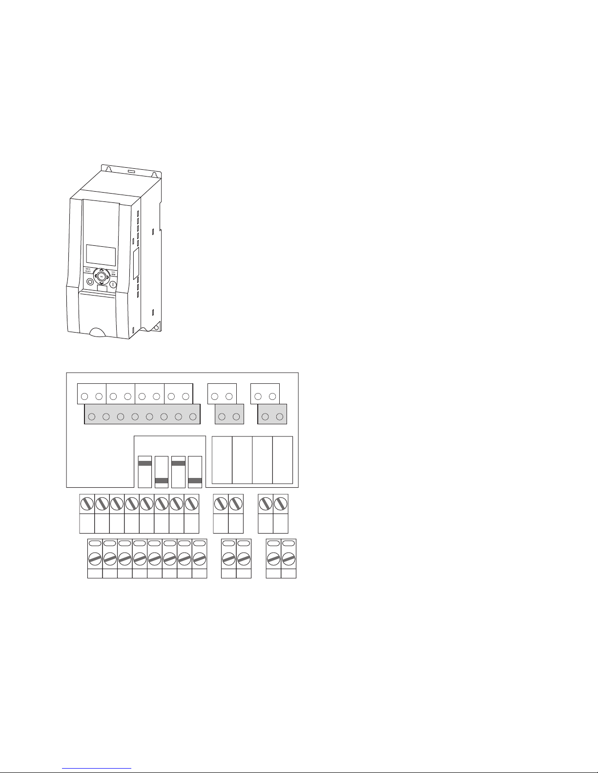
Figure 1. M-Max Series Variable Frequency Drive
Figure 2. Control Signal Terminals
This quick reference guide contains selected information
about the M-Max Series variable frequency drives.
This quick reference guide is a summary of manual
MN04020001E and contains technical data, parameter lists
and information about operating the variable frequency drives
with a new pump application software variant. It is intended
to support experienced, qualified users in the use of the
M-Max Series variable frequency drive.
It is assumed that you have thoroughly read manual
MN04020001E and that the variable frequency drive has
been correctly installed and commissioned as described in
manual MN04020001E and installation instructions
IL04020001E.
M-Max Series VFD pump application MN040046EN—June 2018 www.eaton.com 1

Step 2—M-Max™ Series overview
Writing conversions
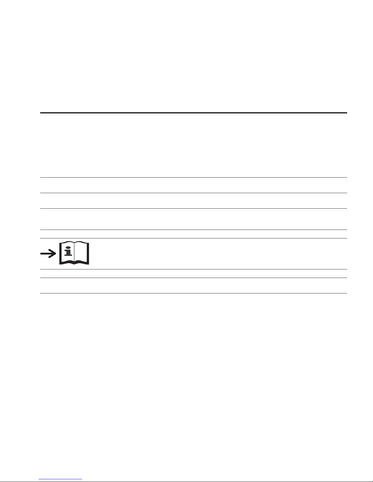
The symbols used in this manual have the following meanings:
P Indicates instructions to be followed.
Table 1. Symbols
Symbol Description
Indicates useful tips and additional information.
Caution!
warns of the risk of material damage.
Warning!
Warns about the possibility of serious property damage and minor injuries.
Danger!
Warns about the possibility of major property damage and serious injuries or death.
In order to make it easier to follow the manual, the name of the current chapter is shown in the header of
the left-hand page and the name of the current section is shown in the header of the right-hand page.
This does not apply to pages at the start of a chapter or to empty pages at the end of a chapter.
In order to make it easier to understand some of the figures included in this manual, the housing of the
variable frequency drive, as well as other safety-relevant parts, have been left out. However, it is
important to note that the variable frequency drive must only be operated with its housing placed
properly, as well as with all required safety-relevant parts.
All the specifications in this manual refer to the hardware and software versions documented in it.
For more detailed indications and explanations on project planning, installation, and parameter
configuration, please consult manual MN04020001E
The complete documentation for the M-Max Series of frequency converters is stored electronically on
a CD-ROM. This CD-ROM is part of the scope of supply.
Additional information on the series described here can be found on the Internet under:
www.eaton.com/M-Max
2 M-Max Series VFD pump application MN040046EN—June 2018 www.eaton.com
Rated operational data on the nameplate
The device-specific rated operational data for M-Max Series
variable frequency drives is shown on the nameplate on the
device's side and on the back of the control signal terminal
cover.
Table 2. Nameplate Inscriptions
Label Meaning
MMX34AA3D3F0-0 Part no.:
MMX = M-Max Series variable frequency drive
3 = Three-phase power connection
4 = 400V voltage category
AA = Instance (Software version A and alphanumerical display)
3D3 = 3.3A rated current (3-decimal-3)
F = Integrated radio interference suppression filter
0 = IP20 protection class
0 = No integrated optional assembly
Input Power connection rating:
Three-phase AC voltage (U
Output Load side (motor) rating:
Three-phase AC voltage (0 – U
Power Assigned motor rating
1.1 kW at 400 V/1.5 hp at 460V for a four-pole internally cooled or surface-cooled three-phase asynchronous motor
(1500 rpm at 50 Hz/ 1800 rpm at 60 Hz)
S/N Serial number
Variable frequency drive is an electrical apparatus.
Read the manual (in this case
3~ AC), 380 – 480V voltage, 50/60 Hz frequency, input phase current (4.0A)
e
), output phase current (3.3A), output frequency (0 – 320 Hz)
e
MN04020001E) before making any electrical connections and commissioning.
Step 2—M-Max™ Series overview
The inscription of the nameplates has the following meaning
(example) as shown in Table 2.
IP20/Open Type Degree of protection of the enclosure: IP20, UL
40W09 Manufacturing date
Calendar week 40 of the year 2009
Mains voltages
The given rated operational voltages in Table 3 are based on
the standardized rated values in centrally earthed star
networks.
In ring-type networks (e.g., Europe) the rated voltage
corresponds the value of the consumer networks
(e.g., 230V, 400V) at the utility company’s transfer point.
In star-type mains (e.g., North America) the rated voltage
at the utility company’s transfer point is higher than in the
consumer network. For example: 120V R 115V, 240V R
230V, 480V R 460V.
®
(cUL®) Open type
M-Max Series VFD pump application MN040046EN—June 2018 www.eaton.com 3
Step 2—M-Max™ Series overview
Table 3. General Rated Operational Data
Technical data Unit Value
General
Standards and regulations EMC: IEC/EN 61800-3,
Safety: IEC/EN 61800-5, UL 508C
Certifications and manufacturer’s
declarations on conformity
Production quality RoHS, ISO
Climatic proofing < 95%, average relative humidity, noncondensing (EN 50178)
Air quality
Chemical vapors IEC 721-3-3: Device in operation, Class 3C2
Mechanical particles IEC 721-3-3: Device in operation, Class 3S2
Ambient temperature
Operation °C –10 to +50
Storage °C –40 to +70
Installation altitude H 0 – 1000m above sea level, over 1000m with 1% power reduction per 100m, maximum 2000m,
Mounting position Vertical (± 90 degrees lateral rotation)
Protection type IP20
Busbar tag shroud BGV A3 (VBG4, finger and back-of-hand safe)
Overvoltage category/degree of pollution —
Mechanical shock resistance IEC 68-2-27
Vibration EN 60068-2-6
Emitted interference with internal EMC filter
(maximum motor cable length)
MMX11 C2 (5m), C3 (30m)
MMX12, MMX32 C2 (5m), C3 (30m)
MMX34 C2 (5m), C3 (30m)
Power Section
Rated operational voltage at 50/60 Hz ±10%
MMX11 U
MMX12 U
MMX32 U
MMX34 U
e
e
e
e
EMC: CE, CB, c-Tick
Safety: CE, CB, UL, cUL, phenum rated
®
9001
1
at maximum +50ºC ambient temperature.
2000m maximum for corner grounded device, 4500m for non-corner grounded device
Storage and transport: 15g, 11 ms (in the packaging)
UPS drop test (for applicable UPS weights)
3 – 150 Hz, oscillation amplitude 1 mm (Peak)
at 3 – 15.8 Hz, maximum acceleration amplitude 1g at 15.8 – 150 Hz
C2: Class A in 1st environment (residential area with commercial utilization)
C3: Class A in 2nd environment (Industrial)
1 AC 115V (110V – 15% …120V + 10%)
1 AC 230V (208V – 15% …240V + 10%)
3 AC 230V (208V – 15% …240V + 10%)
3 AC 400V (380V – 15% …480V + 10%)
4 M-Max Series VFD pump application MN040046EN—June 2018 www.eaton.com

Step 2—M-Max™ Series overview
Table 3. General Rated Operational Data, continued
Technical data Unit Value
Power Section (continued)
Mains network configuration
(AC power supply network)
Mains switch-on frequency Maximum one time per minute
Mains current THD >120%
Short-circuit current max. < 50 kA
Mains frequency f
Pulse frequency (switching frequency
of the inverter)
LN
f
PWM
Operating mode V/Hz-characteristic curve control (WE), sensorless vector control (open loop)
Output voltage U
Output frequency f
2
2
Frequency resolution (set point value) Hz 0.01
Rated operational current I
e
Overload current 150% for 60s every 600s
Starting current 200% for 2s every 20s
Braking torque Maximum 30% M
Control Section
Control voltage (output) Vdc 24, max. 50 mA
Reference voltage (output) Vdc 10, max. 10 mA
Input, digital, parameter definable 6 x, max. +30 Vdc, R
Permitted residual ripple with external control voltage
(+24V)
Input, analog, parameter definable 2 x 0 – +10 Vdc , Ri > 200k ohm /0 (4) – 20 mA, RB ~ 200 ohm
Resolution Bit 10
Output, analog, parameter definable 1 x 0 – 10 Vdc, max. 10 mA
Resolution Bit 10
Output, digital, parameter definable 1 x Transistor, max. 48 Vdc, max. 50 mA
Output relay, parameter definable 1 x N/O 250 Vac maximum 2A/250 Vdc, maximum 0.4A
Output relay, parameter definable 1 x C/O 250 Vac maximum 2A/250 Vdc, maximum 0.4A
Serial interface RS-485/Modbus
Note
1
With MMX34AA014F0-0, the maximum permitted ambient temperature is
limited to +40 ºC and the maximum pulse frequency (fPWM) to 4 kHz.
Center-point grounded star network (TN-S network)
Phase grounded AC networks are not permitted.
50/60 Hz (45 – 66 Hz ±0%)
1 kHz – 16 kHz (WE: 6 kHz)
1
3 AC 230V (MMX11), 3 AC Ue (MMX12, MMX32, MMX34)
0 – 320 Hz (WE: 0 – 50 Hz)
100% continuous current at maximum +50ºC ambient temperature
for all sizes up to maximum 100% MN only as of size MMX34…4D3…
a/Ua
®
N
i
RTU
> 12k ohm
with external braking resistance
Max. 5% U
M-Max Series VFD pump application MN040046EN—June 2018 www.eaton.com 5
Step 3—Technical data
Step 3—Technical data
Table 4. Technical data
Rated
Operational
Current
I
e
Part Number
[A] [A] [kW] [A]
Power Connection Voltage: 1 AC 115V, 50/60 Hz (94 – 132V ± 0%, 45 – 66 Hz ± 0%)
MMX11AA1D7… 1.7 2.6 0.25 1.4 1/3
MMX11AA2D4… 2.4 3.6 0.37 2.0 1/2 2.2 FS2
MMX11AA2D8… 2.8 4.2 0.55 2.7 3/4 2.2 FS2
MMX11AA3D7… 3.7 5.6 0.75 3.2 1 3.2 FS2
MMX11AA4D8… 4.8 7.2 1.10 4.6 1-1/2 4.2 FS3
Power Connection Voltage: 1 AC 230V, 50/60 Hz (177 – 264V ± 0%, 45 – 66 Hz ± 0%)
MMX12AA1D7… 1.7 2.6 0.25 1.4 1/3
MMX12AA2D4… 2.4 3.6 0.37 2.0 1/2 2.2 FS1
MMX12AA2D8… 2.8 4.2 0.55 2.7 3/4 2.2 FS1
MMX12AA3D7… 3.7 5.6 0.75 3.2 1 3.2 FS2
MMX12AA4D8… 4.8 7.2 1.10 4.6 1-1/2 4.2 FS2
MMX12AA7D0… 7.0 10.5 1.50 6.3 2 6.8 FS2
MMX12AA9D6… 9.6 14.4 2.20 8.7 3 9.6 FS3
Power Connection Voltage: 3AC 230V, 50/60 Hz (177 – 264V ± 0%, 45 – 66 Hz ± 0%)
MMX32AA1D7… 1.7 2.6 0.25 1.4 1/3
MMX32AA2D4… 2.4 3.6 0.37 2.0 1/2 2.2 FS1
MMX32AA2D8… 2.8 4.2 0.55 2.7 3/4 2.2 FS1
MMX32AA3D7… 3.7 5.6 0.75 3.2 1 3.2 FS2
MMX32AA4D8… 4.8 7.2 1.10 4.6 1-1/2 4.2 FS2
MMX32AA7D0… 7.0 10.5 1.50 6.3 2 6.8 FS2
MMX32AA011… 11.0 14.4 2.20 8.7 3 9.6 FS3
Power Connection Voltage: 3 AC 400V/460V, 50/60 Hz (323 – 528V ± 0%, 45 – 66 Hz ± 0%)
MMX34AA1D3… 1.3 2.0 0.37 1.1 1/2 1.1 FS1
MMX34AA1D9… 1.9 2.9 0.55 1.5 3/4 1.6 FS1
MMX34AA2D4… 2.4 3.6 0.75 1.9 1 2.1 FS1
MMX34AA3D3… 3.3 5.0 1.10 2.6 1-1/2 3 FS2
MMX34AA4D3… 4.3 6.5 1.50 3.6 2 3.4 FS2
MMX34AA5D6… 5.6 8.4 2.20 5.0 3 4.8 FS2
MMX34AA7D6… 7.6 11.4 3.00 6.6 4 7.6 FS3
MMX34AA9D0… 9.0 13.5 4.00 8.5 5.5 7.6 FS3
MMX34AA012… 12.0 18.0 5.50 11.3 7-1/2 11 FS3
MMX34AA014… 14.0 21.0 7.50
Notes
1
Rated motor currents for normal four-pole internally cooled and surface-cooled three-phase asynchronous motors
(1500 rpm at 50 Hz, 1800 rpm at 60 Hz).
2
Calculated motor rating (no normalized value). The mains voltage of 115V is raised to 230V (output voltage) through
an internal voltage double connection.
3
Allocated motor output at a maximum ambient temperature of +40ºC and a maximum pulse frequency of 4 kHz.
4
Operation with reduced load torque (about –10% MN).
Overload
Current (150%) Assigned Motor Rating
I
e150
P (230V, 50 Hz) P (230V, 60 Hz)
1
3
(15.2)
[hp] [A]
2
2
2
4
3
10
1
2
1.5
2
1.5
2
1.5
14 FS3
Installation
Size
FS2
FS1
FS1
6 M-Max Series VFD pump application MN040046EN—June 2018 www.eaton.com
 Loading...