

Eaton MGR10 Operating Manual
SEFELEC REFERENCE PENT0060
Operating manual MGR10 - English

MGR10 A/B/C - Revision : I (for 7.0 software revision) 2
WARRANTY:
SEFELEC warrants that units are free from defects in material and workmanship.
SEFELEC warrants also that, when properly used, that units will perform in
accordance with specifications of this manual.
If within one year after original delivery it is found not to meet this standard, it will
be repaired at no charge in SEFELEC service facility in Lognes.
Changes in the unit not approved by SEFELEC will cancel this warranty.
SEFELEC will not be liable for any indirect damages resulting of the use of the
unit.
This warranty is in lieu of all other warranties.

MGR10 A/B/C - Revision : I (for 7.0 software revision) 3
Table of Contents
SECTION 1. INTRODUCTION .............................................................................................................................................. 5
1.1 OVERVIEW ................................................................................................................................................................... 6
1.2 Definitions and terminology ............................................................................................................................................ 8
1.3 Principles of measurement ............................................................................................................................................... 8
1.4 MGR10 and MGR10A technical specifications ........... ....................................... ........................................................... 9
1.4.1 Measurement Accuracy ......................................................................................................................................... 9
1.4.2 Programmable current ........................................................................................................................................... 9
1.4.3 Accuracy against current level ........................................................... ............. ....... ............. ...... ............. ............. . 9
1.5 MGR10B technical specifications ................................ .................................................... ............................................ 10
1.5.1 Measurement Accuracy ....................................................................................................................................... 10
1.5.2 Programmable current ......................................................................................................................................... 10
1.5.3 Accuracy against current level ........................................................... ............. ....... ............. ............ ....... ............ 10
1.6 MGR10C technical specifications ................................ .................................................... ............................................ 11
1.6.1 Measurement Accuracy ....................................................................................................................................... 11
1.6.2 Programmable current ......................................................................................................................................... 11
1.7 Common specification to all model numbers ............................................................................................................... 12
1.7.1 Temperature compensation .................................................... ....................................... ...................................... 12
1.7.2 Lead resistance ...................................................................................................................................................... 12
1.7.3 Mains supply ............................................................................ .................................................. ........................... 12
1.7.7 Operating conditions : ............................................................. ............................................................................ 13
1.7.8 Weight and Size : .................................................. .......................................................... ...................................... 13
SECTION 2 : SETTING UP THE MGR10 ............................................................................................................................. 14
2.1 Safety information ........................................................................................................................................................ 14
2.2 Unpacking the instrument ............................................................................................................................................. 14
SECTION 3 : ABOUT THE MGR10 ...................................................................................................................................... 15
3.1 The Front Panel ............................................................................................................................................................. 15
3.2 ON/OFF Switch ........................................................................................................................................................... 15
3.3 The Function Keypad ................................................................................................................................................... 15
3.4 Summary of basic functions ......................................................................................................................................... 16
3.5 About the MGR10 Display screen ................................................................................................................................ 18
3.6 About the function keys ................................................................................................................................................. 19
SECTION 4 : SETTING UP MEASUREMENT PARAMETERS ................................ ......................................................... 21
4.1 Range Selection ............................................................................................................................................................ 21
4.2 Current Selection .......................................................................................................................................................... 22
4.3 Measurement Mode ...................................................................................................................................................... 23
4.4 Temperature Compensation .......................................................................................................................................... 28
4.5 Limits ............................................................................................................................................................................ 31
4.6 Data Logging Function ................................................................................................................................................. 33
4.7 General setup menu ...................................................................................................................................................... 36
4.8 Measure/Hold function ................................................................................................................................................. 40
4.9 Measure Stop Function ........................................................................................ ......................................................... 41
4.10 ZERO Function ........................................................................................................................................................... 41
SECTION 5 : MEASURING WITH THE MGR10 ................................................................................................................. 42
5.1 Connecting to the MGR10 ............................................................................................................................................ 42
5.2 Connecting to the resistance ......................................................................................................................................... 43
5.3 Resistance measurement ............................................................................................................................................... 44
5.4 Resistance measurement with temperature compensation ............................................................................................ 44
5.5 Measurement with Limits ............................................................................................................................................. 45
SECTION 6 :REMOTE CONTROL INTERFACE ................................................ ................................................................ 47
6-1 PLC remote control ( option MGR10-02) ..................................................................................................................... 47
6-1-1 Unit setup : ............................................................................................................................................................ 47
6-1- 2 Contact specifications : ........................................................... ............................................................................ 47
6-1-3 Logical states definition : ..................................................................................................................................... 48
6-1- 4 Connection : ......................................................................................................................................................... 48

MGR10 A/B/C - Revision : I (for 7.0 software revision) 4
6-1- 6 How to trigger a measurement : ............................. .......................... .................... ......................... ................... 51
6-1-7 Analog output : ..................................................................................................................................................... 51
6.2 RS232 and IEEE488 PROGRAMMING INTERFACES : ........................................................................................... 53
6.2.1 RS-232 SERIAL INTERFACE ( option MGR10-01 ) .............................................................. ......................... 53
6.2.1.1 Connection ............................................................................................................................................................... 53
6.2.1.2 Front Panel Set-up ................................................................................................................................................... 54
6.2.2 IEEE-488 PARALLEL INTERFACE (OPTION MGR10-06) ............................................................. ............ 56
6.2.2.1 Connection ............................................................................................................................................................... 56
6.2.2.2 Front Panel Set-up ................................................................................................................................................... 56
6.2.2.3 Interface Functions .................................................................................................................................................. 57
6.2.2.4 Single Wire Interface Messages .............................................................................................................................. 58
6.2.2.5 Multiwire Interface Messages (ATN True) ............................................................................................................. 60
6.2.2.6 Device Dependent Messages (ATN False) ............................................................................................................. 62
6.3 PROGRAMMING THE RS-232 & IEEE INTERFACES ............................................................................................ 63
6.3.1 Introduction ................................................................................................................................................................ 63
6.3.2 Configuration & Measurement Commands ................................................................................................................ 66
6.3.3 Data Operation Commands ......................................................................................................................................... 72
6.3.4 Other function Commands .......................................................................................................................................... 75
6.3.5 System Related Commands ........................................................................................................................................ 77
6.3.6 Status Reporting Commands ...................................................................................................................................... 79
6.3.7 RS-232 Interface Commands ...................................................................................................................................... 87
6.3.8 Front Panel Operations ............................................................................................................................................... 87
APPENDIX I : RS-232/IEEE-488 COMMAND SUMMARY ....................................................................................... 88
APPENDIX II : RS-232 Pin Connections........................................................................................................................ 93
APPENDIX III : IEEE-488 Pin Connections .................................................................................................................. 94
APPENDIX IV : RS232 demo programme ..................................................................................................................... 95
APPENDIX V : IEEE488 for National Instrument demo programme ........................................................................... 99
SECTION 7 : ACCESSORIES .............................................................................................................................................. 105
7.1 LEADS ....................................................................................................................................................................... 105
7.2 OPTIONS ................................................................................................................................................................... 105
SECTION 8: MAINTENANCE AND CALIBRATION ....................................................................................................... 106
8.1 PRELIMINARY ......................................................................................................................................................... 106
8.2 INSTRUMENT RETURN .......................................................................................................................................... 106
8.3 MAINTENANCE ....................................................................................................................................................... 106
8.4 CLEANING ................................................................................................................................................................ 107
8.5 CALIBRATION ....................................................................................................................................................... 1076
MGR10 A/B/C - Revision : I (for 7.0 software revision) 5
SECTION 1. INTRODUCTION
Warning : This unit must be used by qualified pe ople. Every precautions for the
use of units connected to the main must be taken during its use. In pa rticular, this
unit must be connected to earth.
The specifications of this manual, the correct operation of the unit as well as the operator’s
security are guaranteed only when the supplied accessories a re used. The measurement probes
can include limitation or protective elements, therefore it is forbidden to modify without written
agreement from SEFELEC company.
In case of use under other conditions than the one specified in this manual, the security of the
user will be in danger.
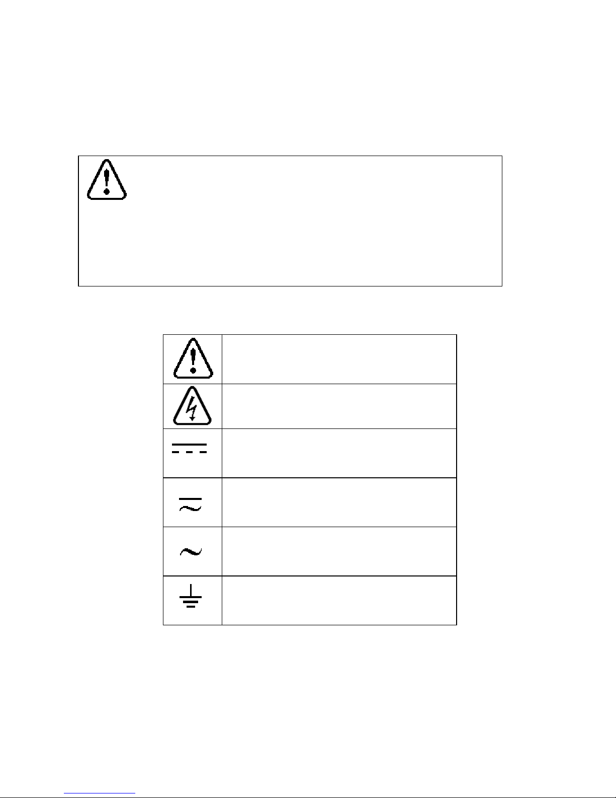
MEANING OF THE DIFFERENT SYMBOLS ON THE INSTRUMENT
Warning (See document attache d)
Warning, risk of electric chock.
DC voltage.
AC and DC voltages.
AC voltage.
Earth connection.
MGR10 A/B/C - Revision : I (for 7.0 software revision) 6
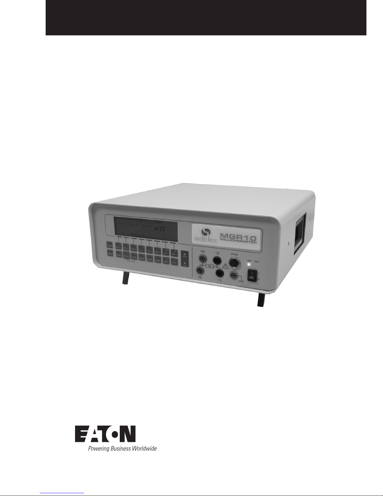
1.1 OVERVIEW
The MGR10 Microhmmeter is a high accuracy instrument designed for industrial and laboratory
resistance measurements.
Features include:
Programmable measuring current user selectable in 100 steps
Temperature Compensation
Hi/Lo Limits with red/green front panel warning Pass/Fail lamps
Switched current mode with automatic averaging ensures elimination of thermal emf errors
Large graphic LCD display for resistance measurement values as well as configuration
settings and statistical results
Advanced functions include data logging a nd statistic al repor ti ng wi t h max/m in, avera ge
values peak to peak values an d standard deviation
Analogue output, IEEE-488 and RS232 communication, and PLC interfaces available for
automated monitoring an d controlling applications
Rear panel terminals available as an option
MGR10 A/B/C - Revision : I (for 7.0 software revision) 7
The MGR10 is a true four wire measuring instrument eliminating the need to compensate for lead
resistance. The measured value is displayed in large characters with decimal point and units k, ,
or m. For maximum accuracy the measuring current may be automatically reversed and the
average of measurement displayed. For measurements on unstable samples, a rolling average filter
is available.
Resistance measurement accuracy is typically 0.03% (1 year specification) and the value may be
displayed with or without temperature compensation, the final accuracy depends upon the current
selected.
The front panel measurement connections are made via 4mm sockets located on the front panel
(rear panel connection is an option). The connection to a Pt100 temperature sensor is made with a
standard DIN connector.
Available models :
Model Description
MGR10 Basic unit
MGR10A Basic unit with batteries power
MGR10B Basic unit for NFC93050 contact resistance measuremen t
MGR10C Basic unit for pyrotechnic measurement

MGR10 A/B/C - Revision : I (for 7.0 software revision) 8
1.2 Definitions and terminology
Standard features of the MGR10 Microhmmeter include:
Direct display of resistance
Illuminated display
Up to 10 Amps measuring current (programmable)
Temperature compensation
Display hold function
Display zero function
4000 event data logger
Statistical reporting
Measuring current reversal
Hi/Lo Limits with Red/Green front panel warning LEDs
Digital filter for smoothing display
1.3 Principles of measurement
The MGR10 generates a constant current which is connected using the +I and -I leads across the
unknown resistance to be measured. Th is current also passes through a stable and accurate inte rnal
standard. The volt drop across the unknown resistance is then measured together with th e volt drop
across the internal standard, the ratio of these two mea sur emen ts is then co mputed and displayed on
the front panel.
MGR10 A/B/C - Revision : I (for 7.0 software revision) 9
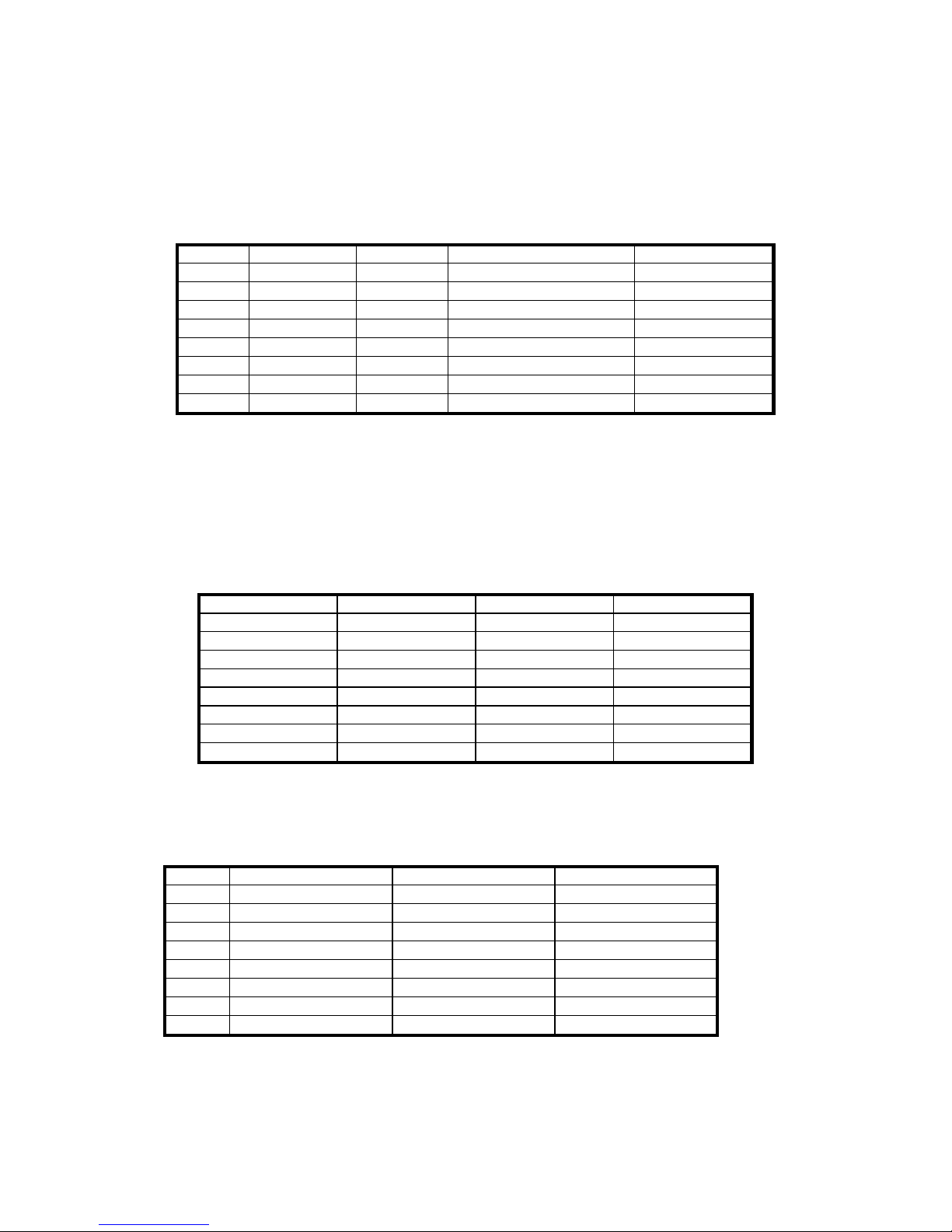
1.4 MGR10 and MGR10A technical specifications
1.4.1 Measurement Accuracy
Range Max. Current Resolution Accuracy at full rated current Temp. Coefficient
30 k 100A 1
±(0.03%Rdg+0.02%FS)
50 ppm
3 k
1mA
100m
±(0.03%Rdg+0.01%FS)
50 ppm
300
10mA
10m
±(0.03%Rdg+0.01%FS)
50 ppm
30
100mA
1m
±(0.03%Rdg+0.01%FS)
50 ppm
3
1A
100
±(0.03%Rdg+0.01%FS)
50 ppm
200m
10A
10
±(0.03%Rdg+0.01%FS)
50 ppm
30m
10A
1
±(0.03%Rdg+0.01%FS)
50 ppm
3m
10A
100n
±(0.03%Rdg+0.02%FS)
50 ppm
The accuracy is quoted at full rated current in SLOW measurement speed and the display count
is 30,000 plus sign and unit.
FS = Full Scale
1.4.2 Programmable current
The measurement current is adjustable on each resistance range as follows:
Range Max Current Min Current Steps
30 k 100A 10A 1A
3 k
1mA
100A 10A
300
10mA 1mA
100A
30
100mA 10mA 1mA
3
1A 100mA 10mA
200m
10A 1A 100mA
30m
10A 1A 100mA
3m
10A 1A 100mA
The accuracy of current is ±0.1% .
Open circuit voltage is 5 V +/-5%
1.4.3 Accuracy against current level
Range 100% Current 50% Current 10% Current
30 k
±(0.03%Rdg+0.02%FS) ±(0.04%Rdg+0.02%FS) ±(0.05Rdg+0.02%FS)
3 k
±(0.03%Rdg+0.01%FS) ±(0.04Rdg+0.01%FS) ±(0.05Rdg+0.01%FS)
300
±(0.03%Rdg+0.01%FS) ±(0.04Rdg+0.01%FS) ±(0.05Rdg+0.01%FS)
30
±(0.03%Rdg+0.01%FS) ±(0.04Rdg+0.01%FS) ±(0.05Rdg+0.01%FS)
3
±(0.03%Rdg+0.01%FS) ±(0.04Rdg+0.01%FS) ±(0.05Rdg+0.01%FS)
200m
±(0.03%Rdg+0.01%FS) ±(0.04Rdg+0.01%FS) ±(0.05Rdg+0.01%FS)
30m
±(0.03%Rdg+0.01%FS) ±(0.04Rdg+0.01%FS) ±(0.05Rdg+0.01%FS)
3m
±(0.03%Rdg+0.02%FS) ±(0.04Rdg+0.02%FS) ±(0.05Rdg+0.02%FS)
MGR10 A/B/C - Revision : I (for 7.0 software revision) 10
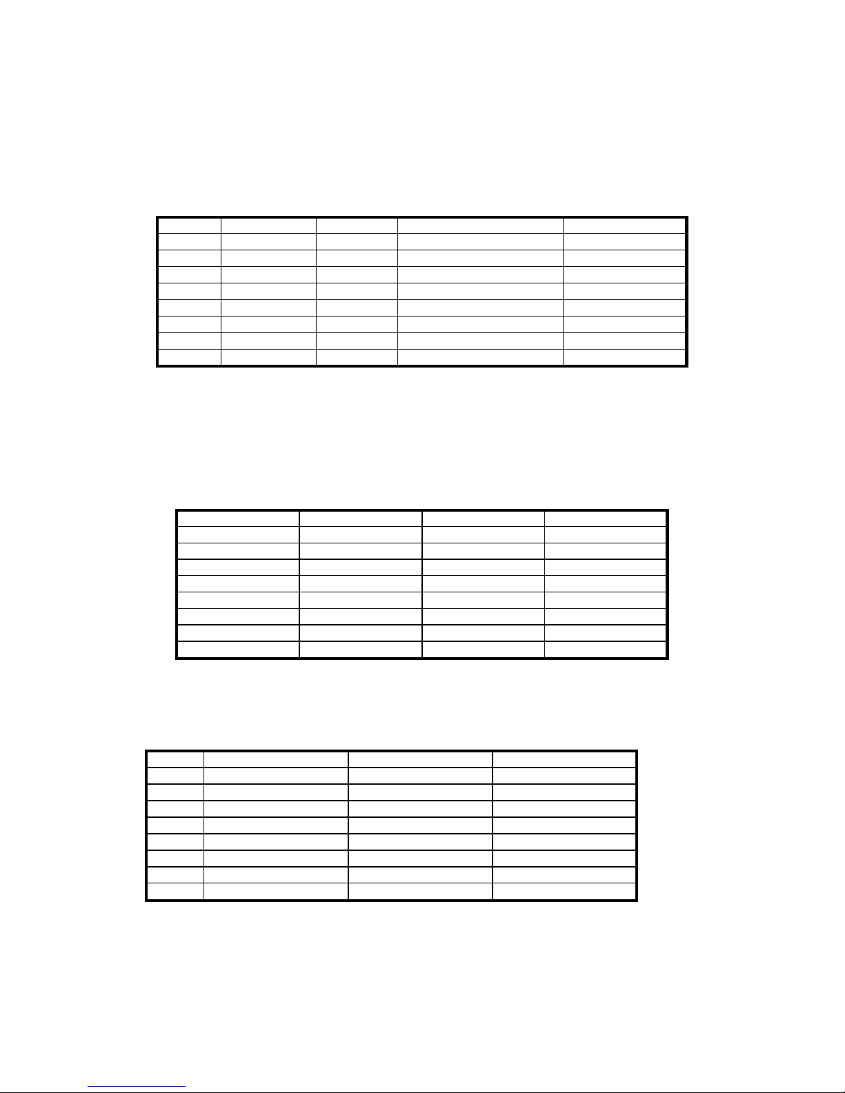
1.5 MGR10B technical specifications
1.5.1 Measurement Accuracy
Range Max. Current Resolution Accuracy at full rated current Temp. Coefficient
30 k 100A 1
±(0.03%Rdg+0.02%FS)
50 ppm
3 k
1mA
100m
±(0.03%Rdg+0.01%FS)
50 ppm
300
10mA
10m
±(0.03%Rdg+0.01%FS)
50 ppm
30
100mA
1m
±(0.03%Rdg+0.01%FS)
50 ppm
3
100mA
100
±(0.05%Rdg+0.01%FS)
50 ppm
200m
100mA
10
±(0.05%Rdg+0.01%FS)
50 ppm
30m
Not available
3m
Not available
The accuracy is quoted at full rated current and the display count is 30,000 plus sign and unit.
FS = Full Scale
1.5.2 Programmable current
The measurement current is adjustable on each resistance range as follows:
Range Max Current Min Current Steps
30 k 100A 10A 1A
3 k
1mA
100A 10A
300
10mA 1mA
100A
30
100mA 10mA 1mA
3
100mA 10mA 1mA
200m
100mA 10mA 1mA
30m
Not available
3m
Not available
The accuracy of current is ±0.1% .
Open circuit voltage is 5 V +/-5% . Can be limited to 20 or 50 mV to comply with NFC93050
1.5.3 Accuracy against current level
Range 100% Current 50% Current 10% Current
30 k
±(0.03%Rdg+0.02%FS) ±(0.04%Rdg+0.02%FS) ±(0.05Rdg+0.02%FS)
3 k
±(0.03%Rdg+0.01%FS) ±(0.04Rdg+0.01%FS) ±(0.05Rdg+0.01%FS)
300
±(0.03%Rdg+0.01%FS) ±(0.04Rdg+0.01%FS) ±(0.05Rdg+0.01%FS)
30
±(0.03%Rdg+0.01%FS) ±(0.04Rdg+0.01%FS) ±(0.05Rdg+0.01%FS)
3
±(0.05%Rdg+0.01%FS) ±(0.06Rdg+0.01%FS) ±(0.07Rdg+0.01%FS)
200m
±(0.05%Rdg+0.01%FS) ±(0.06Rdg+0.01%FS) ±(0.07Rdg+0.01%FS)
30m
Not available
3m
Not available
MGR10 A/B/C - Revision : I (for 7.0 software revision) 11
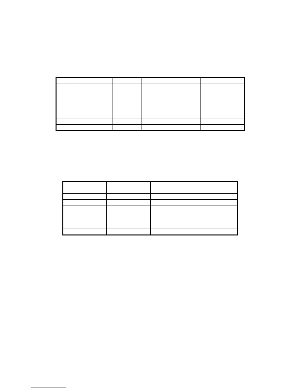
1.6 MGR10C technical specifications
1.6.1 Measurement Accuracy
Range Max. Current Resolution Accuracy at full rated current Temp. Coefficient
30 k 10A 1
±(0.05%Rdg+0.02%FS)
50 ppm
3 k
0,1mA
100m
±(0.05%Rdg+0.01%FS)
50 ppm
300
1mA
10m
±(0.05%Rdg+0.01%FS)
50 ppm
30
10mA
1m
±(0.05%Rdg+0.01%FS)
50 ppm
3
10mA
100
±(0.05%Rdg+0.01%FS)
50 ppm
200m
Not available
30m
Not available
3m
Not available
The accuracy is quoted at full rated current and the display count is 30,000 plus sign and unit.
FS = Full Scale
1.6.2 Programmable current
The measurement current is not adjustable on each resistance range
Range Max Current Min Current Steps
30 k 10A 10A
Not available
3 k 100A 100A
Not available
300
1mA 1mA Not available
30
10mA 10mA Not available
3
10mA 10mA Not available
200m
Not available
30m
Not available
3m
Not available
The accuracy of the current i s ± 1% .
Open circuit voltage is 2 V +/-5% .

MGR10 A/B/C - Revision : I (for 7.0 software revision) 12
1.7 Common specification to all model numbers
1.7.1 Temperature compensation
The accuracy of the temp erature measur emen t is ±0.1% and uses a standard Pt1 00 sensor. This
accuracy does not include errors due to the sen sor itself. The tempe rature measureme nt range is
0…+40C and the resistance measurement is referenced to 20C when this option is used.
Accuracy of the MGR10-04 sensor : +/- ( 0.2% + 1°C)
1.7.2 Lead resistance
A maximum lead resistance of 0.5 / Imes ( = 0.05 for 10A and 500 for 1mA ) is
permissible in each of the four measuring leads.
1.7.3 Mains supply
Universal power inlet
Mains : 115/230V~ 10% single phase 47 to 63 Hz.
Power consumption : 40VA without load, 70 VA maxim um .
Switching from 115 to 230 volts by switch in the line input plug.
Temporized fuse protective in rear panel
- 2AT for 230V 4AT for 110V.
Battery powered with built in charger ( MGR10A version)
The two batteries used are 5Ah, and the following performance can be expected from
fully charged batteries:
o Digital :11 hours continuous use, with backlight on, an d IEEE and PLC cards
fitted.
o Analogue: Over 6000 simple measurements in FAST mode, using 10A
measuring current. (Or approximately 3000 measurements using SLOW
mode).
The battery condition is consta n tly monitored, and if it is low, a warning symbol is displayed .In
this situation operate as follows :
Connect a mains cable on the unit rear m ains soc ket
Connect the mains cable on the mains
Switch the rear panel switch in the ON position
The FAST red Led lamp should light on to indicate the battery charging mode
When the red Led lights off , the charge is over

MGR10 A/B/C - Revision : I (for 7.0 software revision) 13
1.7.7 Operating conditions :
The instrument must be used inside, in horizontal position or on tripode.
Temperature :
In storage : -10°C to +60°C.
In operation : 0°C to +45°C.
Accuracy is rated after half an hour of warm up and for a relative humidity < 50%.
Altitude : up to 2000 meters
Max. humidity rate : 80% for a temperature of 31°C.
1.7.8 Weight and Size :
Size : 131 x 339 x 324 mm (H W D)
Weight : 9.8 kg mains version
: 12 kg mains and battery version
Over voltage category :
CAT II.
Rate of pollution :
Pollution 2 : Occasional conductive pollution only by condensation.
Safety class :
Class I instrument : Earth protection by mains connection.
MGR10 A/B/C - Revision : I (for 7.0 software revision) 14
SECTION 2 : SETTING UP THE MGR10
2.1 Safety information
Please read and follow these important safety instructions:
Read the safety information at the beginning of this manual before operating the MGR10;
Make the necessary electrical safety connection checks. In particular, select the correct line voltage
and make sure that the correct fuse is installed. Incorrect voltage or fuse selection present both an
electrical safety and a fire haza rd. Ensure that the rear panel fan is operating and that the vent is not
blocked.
When connecting to an electrical supply mains supply, the mains cord provided with the equipment
should be used, and connected only to a mains supply with a suitable earth connection. Under no
circumstance should the equipment be operated with earth disconnected.
2.2 Unpacking the instrument
When you unpack the MGR10, check that the following items are present before starting to use the
unit:
1 x MGR10 Microhmmeter
1 x Mains Cord
1 x Operating manual
1 x Calibration Certificate
Please contact the Sefelec Customer Support Team immediately if any of these items are missing or
damaged.
MGR10 A/B/C - Revision : I (for 7.0 software revision) 15
SECTION 3 : ABOUT THE MGR10
This section introduces you to the features and functions of the MGR10 Microhmmeter
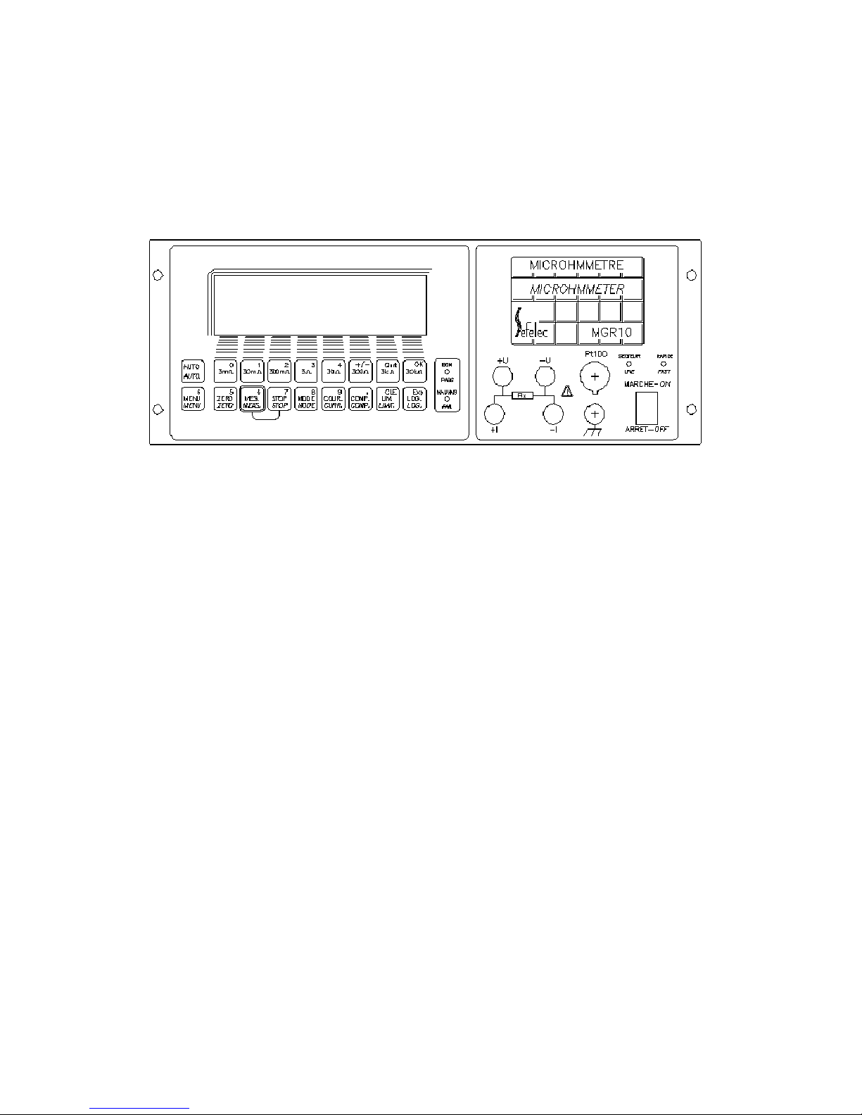
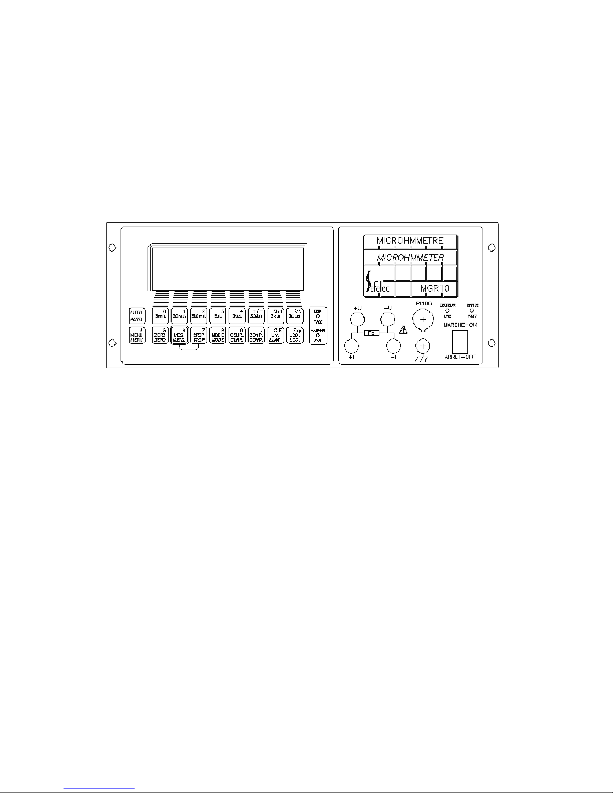
3.1 The Front Panel
3.2 ON/OFF Switch
The On/Off switch switches the MGR10 on and off. During Power On the last measurement
function setup is restored. The rear mounted cooling fan will always run and the cooling vent must
not be blocked.
3.3 The Function Keypad
All MGR10 measurements and programming facilities are accessed through the function keypad.
A brief description of key functions is given in the following table. For a detailed description of
how to use the keys to configure a nd ope r a t e t he MGR10, refer to section 5.
MGR10 A/B/C - Revision : I (for 7.0 software revision) 16
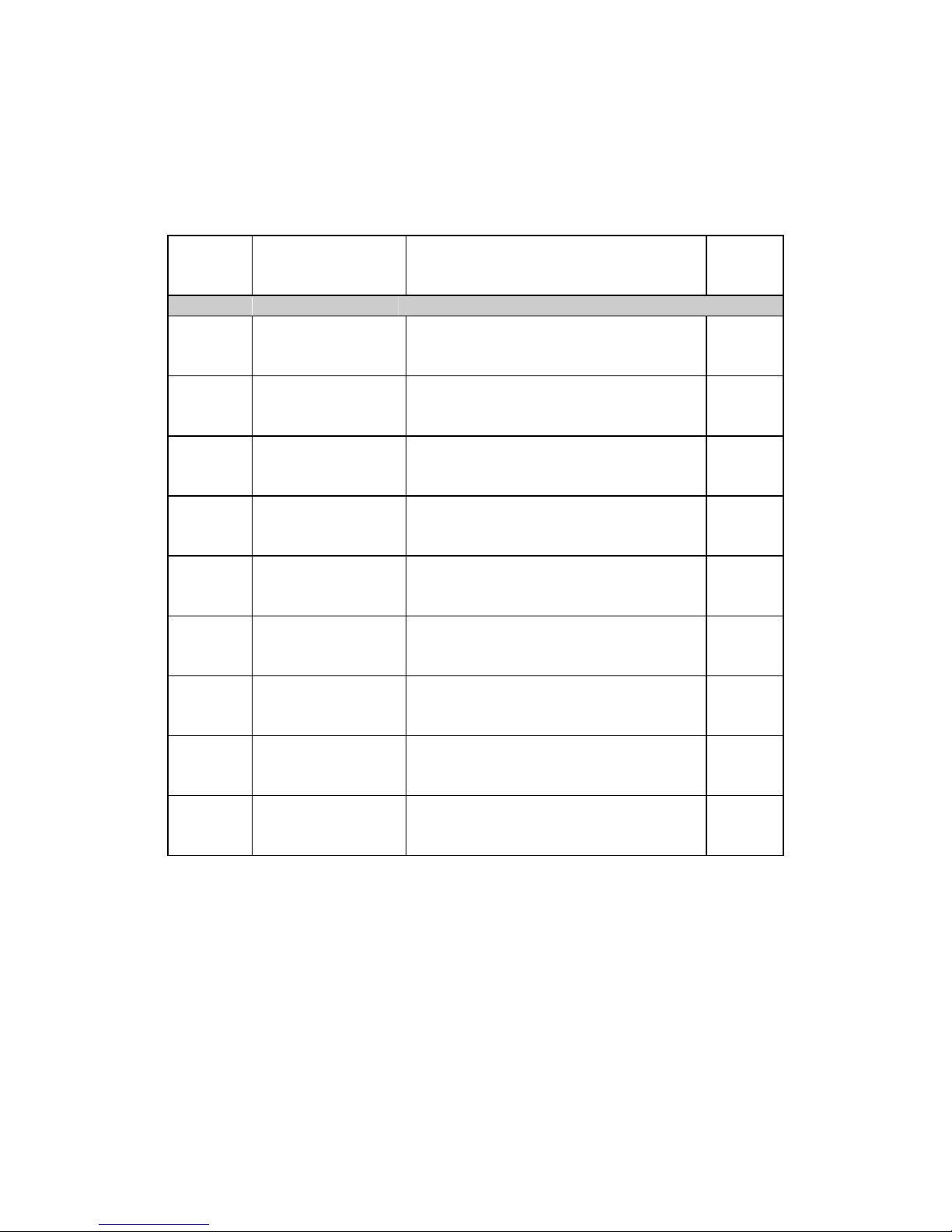
3.4 Summary of basic functions
Key
Symbol
Description
Function
Direct
function
or menu
Selection of Range
3m
Selects 3m range
Selects and displays the m easured value
using the 3m range
Direct
from
keypad
30m
Selects 30m range
Selects and displays the m easured value
using the 30m range
Direct
from
keypad
200m
Selects 200m
range
Selects and displays the m easured value
using the 200m range
Direct
from
keypad
3
Selects 3 range
Selects and displays the m easured value
using the 3 range
Direct
from
keypad
30
Selects 30 range
Selects and displays the m easured value
using the 30 range
Direct
from
keypad
300
Selects 300 range
Selects and displays the m easured value
using the 300 range
Direct
from
keypad
3k
Selects 3k range
Selects and displays the m easured value
using the 3k range
Direct
from
keypad
30k
Selects 30k range
Selects and displays the m easured value
using the 30k range
Direct
from
keypad
Auto
selects autorange The instrument will select the optimum
range required and display the measured
value
Direct
from
keypad
MGR10 A/B/C - Revision : I (for 7.0 software revision) 17
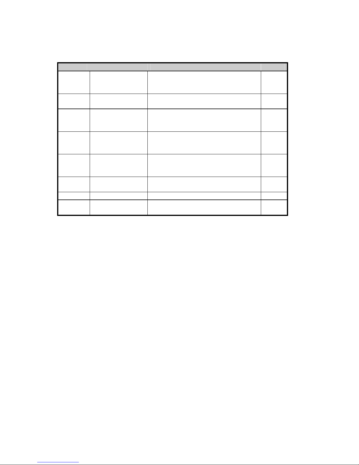
Setting up measurement options
CURR
Current selection Selects the current to be used for
measurement plus single polarity or
switched average
Menu
COMP
Temperature
compensation
Selects temperature compensation Menu
ZERO
Measurement
display zero
function
Nulls the display at the current reading
and displays measured values relative to
the null value
Direct
from
keypad
MES
Measure run/hold Display hold function triggers
measurement and data logger cycles.
Direct
from
keypad
STOP
Measure stop/start Stop s the current measurement and
disconnects the measurement current
Direct
from
keypad
LOG
Data logging
function
Selects the data logging and statistical
analysis menu functions
Menu
LIMIT
Limit functions Selects Hi/Lo limit menu Menu
MENU
Menu functions Selects interface options and calibration
functions
Menu
MGR10 A/B/C - Revision : I (for 7.0 software revision) 18
3.5 About the MGR10 Display screen
The liquid crystal graphic display clearly indicates the measured resistance and measurement status as
well as displaying available menu options and measurement analysis when selected.
Figure 3.5.1 - Example of Resistance Measurement Mode
The keypad below the display screen contr o ls the MGR10. Some keys perform a function directly. For
example, selects 3m range.
Other keys switch the display to configuration mode which allows you to select options through a
series of menus.
The option menus all follow the same format. The conf iguration mode is in dicated on the screen by a
dashed line displayed directly below the main reading. An instruction prompt under the dashed line
indicates the current menu. The available menu options are displayed on the bottom row of the display
as shown in figure 3.5. Press the corresponding function key to select an option.
AUTO1: 30m 10.0A (AVE) Slow
+ 18.000 m
T= +20.0C (EXT) R
20
= 18.006m (Cu)
Meas Cont
0
3m
MGR10 A/B/C - Revision : I (for 7.0 software revision) 19
Figure 3.5.2 Example of current mode menu
The lines printed on the front panel helps you to link the menu option printed on the screen with the
correct key on the keypad.
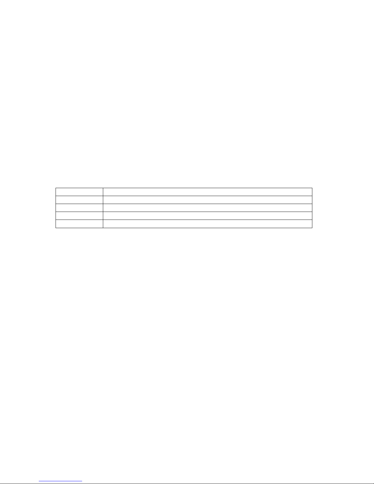
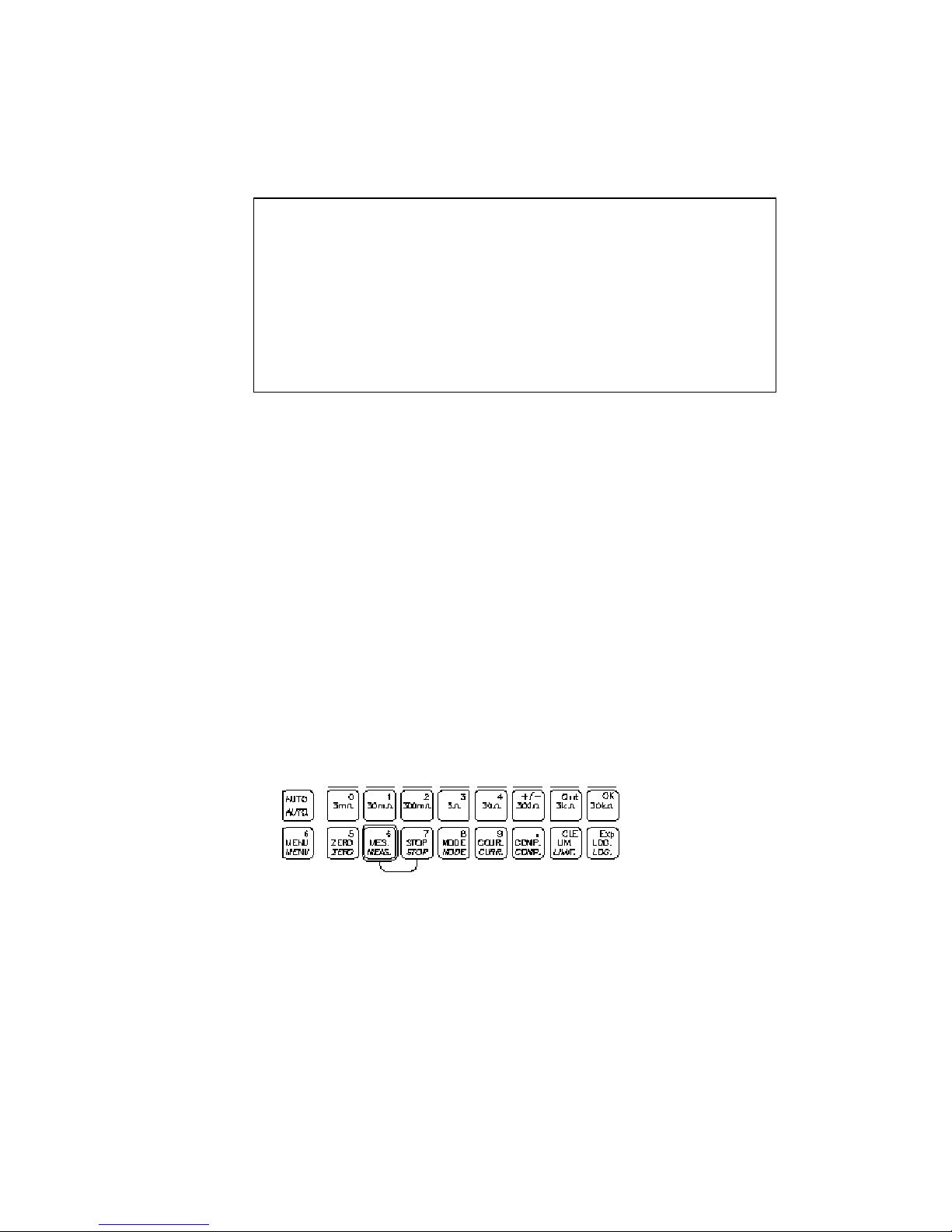
3.6 About the function keys
The top row of function keys are only used to select menu options. The lower row of function keys
is enabled only when entering values; these instances are covered lat er in this section. Both rows of
function keys are shown in figure 3.#
Figure 3.6.1 - Function keys
AUTO1: 30m 10.0A (AVE) Slow
+ 18.000 m
----------------------------------------------------------------------------------------
Powr
+I -I Ave Mode Mag Quit
MGR10 A/B/C - Revision : I (for 7.0 software revision) 20
The [Quit] and [OK] menu options consistently use the following keys.
Use the [Quit] k ey to leave a menu or return to the Resi stance Measurement mo de screen. Use the
[OK] key to confirm a particular choice and continue to the next set of menu options.
Not all function keys are used to access the Configuration Mode. Some just invoke the function
which is printed on the key. For example pressing
immediately sets the measured value displayed to zero.
The rest of this section describes each key in det ail and gives examples of how to configure the
measurement to your requirements.
The last used set up conditions are stored when the instrument is turned off and restored upon
switch on.
Quit
3k
OK
30k
5
ZERO
ZERO

MGR10 A/B/C - Revision : I (for 7.0 software revision) 21
SECTION 4 : SETTING UP MEASUREMENT PARAMETERS
4.1 Range Selection
Two modes of range selection are possible, Manual and Auto range. The 8 ranges may be selected
individually by pressing the appropriate range key. The range selected is indicated on the top left
hand side of the display. Auto range is selected using [AUTO] key.
This key toggles the selected function as follows; AUTO1 auto ranges starting with the highest
range,. AUTO2 auto ranges starting with the current range selected; Range manual range is
selected.
The range mode selected is indicated in the top left corner of the display.
WARNING : The maximum measurement current is 10 A on the 3 lowest ranges , check if the
current level intensity selected cannot damaged the resistor under test .
AUTO.
AUTO.
MGR10 A/B/C - Revision : I (for 7.0 software revision) 22
4.2 Current Selection
Press
Selects the current configuration menu;
+I , -I or Ave :
Select the current direction by pressing [+I] , [ -I ] or [Ave] , this function reverses automatically
the current direction and display the average of the 2 measured values : this cancels the errors
coming from the emf effect . The polarity or the average mode are displayed on the top line of the
LCD screen .
Mag :
Press on [Mag] to change the current intensity , as a percentage between 10 and 100 % of the
maximum value .
Press on [Chg] to modify the current value
Enter the requested percentage with the numeric keypad ( numbers are located in the right
upper corner of the keys )
Press on [OK] to enter the value.
Press on [OK] to go back to the previous page
The current value is displayed on the center top line of the LCD screen . The % value is
applied to all the ranges .
Press on [QUIT ] to escape the menu .
+I -I Ave Mag Quit
9
COUR
CURR.
MGR10 A/B/C - Revision : I (for 7.0 software revision) 23
4.3 Measurement Mode
Press on :
to select the measurement mode options.
For the greatest flexibility and v ersatility of meas urement the MGR10 has man y advanced featu res
which can be selected from this m enu.
The
km function gives the possib ility to display the measured resistan ces on a known leng th of
cables computed to the value for 1 kilometer.
:
Press on [] to select a resistance display in Ohms ( standard display )
/km :
Press on [ /km] to select a resistance display in Ohms per kilometer
Press on [ No. ] to modify the number of cable connected in series or parallel
o Enter a number between 1 and 99 wit h the numeric keypad
o Press on [OK] to enter the value
Press on [ Len ] to modify the cabl e l ength
o Enter the value according to unity with the numeric keypad
o Press on [OK] to enter the value
Press on [ Unit ] to select Meter or Kilometer
o Press on [ meter ] or [ km]
o Press on [OK] to enter the selecti on
Press on [ Conn ] to define if the cables are series or parallel connected .
o Press on [ Ser ] or [ Par ]
o Press on [OK] to enter the selecti on
Press on [OK] to go back to the previous page
-------DISPLAY------- Trig Read
km km Mode Rate Filt Sett Quit
8
MODE
MOD
E

MGR10 A/B/C - Revision : I (for 7.0 software revision) 24
Press on [QUIT ] to escape the menu .
According to the input parameters the unit will display the resistance value for a distance of 1 km.
i.e. :
A measured resistor of 220 ohms on a 100 meters long cable , the value for 1 kilometer will be :
1km/100m x 220 ohms = 2200 ohms
A measured resistor of 220 ohms on a 2000 meters long cable , the value for 1 kilometer will be :
1km/2km x 220 ohms = 110 ohms
A measured resistor of 220 ohms on 2 parallel 100 meters long cables , the value for 1 kilometer
will be : 1km/100m x 220 ohms x 2 = 4400 ohms
A measured resistor of 220 ohms on 2 series 100 meters long cables , the value for 1 kilometer will
be : 1km/100m x 220 ohms / 2 = 1100 ohms
NOTA : the ohm per km value will be displayed in big characters and the true value will be displayed
in small characters ( Rx= 220,00 ohm)
km :
Press on [km] to select the resistance display in kilometers.
Press on [ No. ] to modify the number of cable connected in series or parallel
o Enter a number between 1 and 99 wit h the numeric keypad
o Press on [OK] to enter the value
Press on [ Res ] to modify the resistor per distance unity (km or meter)
o Enter the value according to unity with the numeric keypad
o Press on [OK] to enter the value
Press on [ Unit ] to select Meter or Kilometer
o Press on [ meter ] or [ km]
o Press on [OK] to enter the selecti on
Press on [ Conn ] to define if the cables are series or parallel connected .
o Press on [ Ser ] or [ Par ]
o Press on [OK] to enter the selecti on
Press on [OK] to go back to the previous page
Press on [QUIT ] to escape the menu .
According to the input resistance per meter or kilometer value the unit will display the length of the
cable .i.e. :
A resistor per kilometer of 220 ohm x km on 1 cable with a measured resistance of 220 ohms , the
cable length value will be :
220 ohms / 220 ohmxkm = 1 kilometer
A resistor per kilometer of 220 ohm x km on 2 series cables with a measured resistance of 220
ohms , the cable length value will be :
220 ohms / 220 ohmxkm /2 = 0.5 kilometer
A resistor per kilometer of 220 ohm x km on 2 parallel cables with a measured resistance of 220
ohms , the cable length value will be :
220 ohms / 220 ohmxkm x 2 = 2 kilomete r
NOTA : the km value will be displayed in big characters and the true value will be displayed in small
characters ( Rx= 220,00 ohm)

MGR10 A/B/C - Revision : I (for 7.0 software revision) 25
MGR10 A/B/C - Revision : I (for 7.0 software revision) 26
IMPORTANT NOTICES ON THE /km and km MODES :
1) The
/km and km functions are not operating in RS232 or IEEE488 modes but are op erating
in the PLC mode .
2) The temperature compensation function stays operating .
3) The comparison function with high and low limits , the analog output and the data storage are
not following the
/km and km modes and continue to work on the real Rx valu e in Ohms .
4) The ZERO function is not working in the
/km and km modes
5) Only the SLOW mode allows operating
/km and km functions .
Trig Mode :
Press on [Trig Mode ] to select the measurement trigger modes.
Press on [Cont] to activate the continuous measurement mode
Press on [Sing ] to activate single measurement mode. This mode performs a measurement
and memorizes the value on the display .To trigger a new measurement , press on the
[MES] key .
Press on [OK] to go back to the previous page
Press on [QUIT ] to escape the menu .
Read rate :
Press on [Read rate ] to select the measurement speed
Press on [Slow] to activate a display with large characters and with a rate of 2 measurements
per second which gives the best resolu tio n a n d accuracy .
Press on [Med] to activate a display with large characters and with a rate of 4 measurements per
second which gives the best resolution and accuracy .
Or press on [Fast ] to perform measurement with a rate of 50 per second . This mode is
mainly advised when operating the unit from a remote interface . The measured values are
displayed in small characters and the accuracy is reduced .
Press on [OK] to go back to the previous page
Press on [QUIT ] to escape the menu .
Filt :
Press on [Filt] to select the digital filter, this feature should be used when the sample to be
measured is unstable and the measured value displayed is constantly changing. The filter is a
rolling average of n measurem ents, where n may be set between 1 and 32.
Press on [No. Rdgs] to enter the number of measurements : No of readings : 10 .
Press on [Chg] to change the value and enter the value with the numeric keypad .
Press on [OK] to enter the new value .This value will be displayed in the right upper
corner of the LCD screen if the filter is activated . Filt : n
Or press on [OK] to keep the previous value
Press on [On] to activate the filter mode.

MGR10 A/B/C - Revision : I (for 7.0 software revision) 27
Or press on [Off] to cancel the filter mode
Press on [OK] to go back to the previous page
Press on [QUIT ] to escape the menu .
Sett :
Press on [Sett] to select the Settling Algorithm intended for measuring the resistance of inductive
specimens.
When the ‘MEAS’ button pressed, con tinuous measurements will be made until two consecutive
results are within the selected limit, or until the selected maximum number of measurements has been
reached. In the first case, the final result will be displayed, and in the second case, the message:
“MEASUREMENT ERROR – Current settle faile d” will be displayed. If appropriate, the result (or the
‘error value’) will also be data-logged, sent out on the bus, and sent to the Analogue Output on the PLC
card. Finally, if the Measurement Limits facility is selected, then the PASS/FAIL result will be
displayed.
The Settling facility cannot be used in ‘FAST’ mode, and ‘SLOW’ mode is recommended.
Normally, the Settling facility should be used in ‘SINGLE’ trigger mode, and the above description
assumes this. Howev e r, if ‘CONTINUOUS’ trigger mode is used, then the operation is the same,
except that once the measurement has settled, the settling facility is effectively disabled, and the
MGR10 continues to take measurements without interrupting the current, until ‘STOP’ is pressed.
When ‘MEAS’ is pressed again, the Settling facility will be re-engaged.
Press on [Limit] to enter the number of digits : No of digits : 10 .
Press on [Chg] to change the value and enter the value with the numeric keypad .
Press on [OK] to enter the new value .This value will be displayed in the right upper
corner of the LCD screen if the filter is activated . Sett : n
Or press on [OK] to keep the previous value
Press on [No. Rdgs] to enter the number of measurements : No of readings : 10 .
Press on [Chg] to change the value and enter the value with the numeric keypad .
Press on [OK] to enter the new value .This value will be displayed in the right upper
corner of the LCD screen if the filter is activated . Sett : n
Or press on [OK] to keep the previous value
Press on [On] to activate the settling mode.
Or press on [Off] to cancel the settling mode
Press on [OK] to go back to the previous page
Press on [QUIT ] to escape the menu .

MGR10 A/B/C - Revision : I (for 7.0 software revision) 28
4.4 Temperature Compensation
Press on
to select the setup menu for temperature compensation
The temperature compensation mod e should be used when measuremen ts are required to b e referenced
to 20C. This is particularly useful when measuring materials with a high temperature coefficient such
as copper, as the ambient temperature varies so will the resistance value being measured. Using the
temperature compensation mode references all values back to a temperature of 20C.
The true resistance value measured will be displayed in large digits in the center of the display and the
compensated resistance will be displayed in smaller text below.
The compensation formula is :
))20(1( Ct
Rx
Rc
With : R
t
= resistance value @ t temperature
Rc = resistance @ 20°C
= 3980 ppm/°C or 4100 ppm/°C according to the material
t = measurement temperat ure
Mode :
Press on [Mode] to select the temperature compensation
Press on [Ext] to select an external temperature sensor .This mode require the connection of a
PT100 sensor on the front panel connector named Pt100.
.
COMP
COMP
Compensation : On MANUAL COPPER
Mode Ref On Off Quit

MGR10 A/B/C - Revision : I (for 7.0 software revision) 29
Or press on [Man] to enter manually the compensation temperature .This mode request to the
operator to enter the ambiance temperature .
Press on [Chg] to modify the temperature value
Use the keypad to enter the new value in °C or °F
Press on [OK] to enter the new value
Press again on [OK] to go back to the previous page
Press on [Cu] to select compensati on f or coppe r material with a coefficient : 3980 ppm/C
Or press on [Al] to select compensation for aluminum material with a coefficient : 4100 ppm/C
Or press on [User] to select a coefficient which c an be defined by the operator
Press on [Chg] to modify the coefficient value in ppm/°C
Use the keyboard to enter the new coefficient value
Press on [OK] to enter the new value
Press again on [OK] to go back to the previous page
Press again on [OK] to go back to the previous page
Ref :
Press on [Ref] to select the reference temperature value (standard and initial value set to 20°C)
Press on [UP arrow] or [DOWN arrow] keys to modify the temperature value
Press on [OK] to enter the new value
Press again on [OK] to go back to the previous page
On :
Press on [On] to activate the temperature compensation mode
Off :
Or press on [Off] to cancel the temperature compensation mode
Press on [Quit] to escape the menu

MGR10 A/B/C - Revision : I (for 7.0 software revision) 30
In the compensation mode , the compensated value of the resistance is displayed with big characters
and the true value is displayed with small characters .
Figure 4.4.1 Measurement screen with temperature compensati on
AUTO1: 30m +10.0A (AVE) SLOW
+ 9.619 m
T= + 30.0C (Man) RX = 9.997 m (Cu)
Meas Sing
 Loading...