

Eaton Metalux 14SP4240RT Instruction Manual
Instruction Manual/Directives/Instrucciones
Questions?/ Questions?/¿Preguntas ? 1-800-334-6871 www.eaton.com
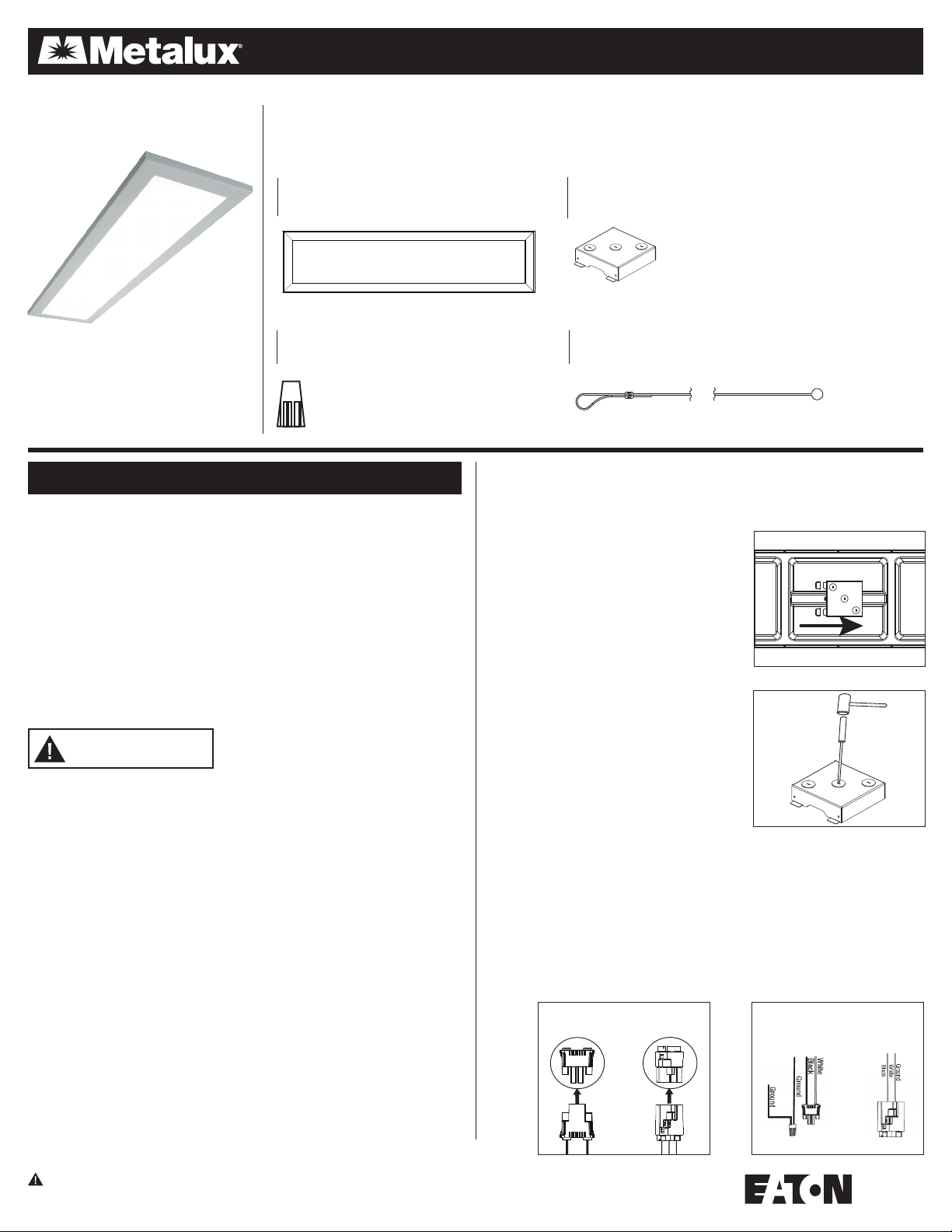
PACKAGING CONTENTS /CONTENU DE L’EMBALLAGE/CONTENIDO DEL PAQUETE
A. Fixture housing assembly
Assemblage du boîtier du luminaire
Unidad de alojamiento de la luminaria
B. Fixture JBOX cover
Couvercle de la boîte de jonction du luminaire
Cubierta de la caja de derivaciones de la luminaria
C. Wire Nut
Serre-fils
14SP4240RT
Tuerca para cables
ENGLISH
ITEMS REQUIRED
(Purchase separately)
• Flat head screwdriver
• Wire Cutters
• Hammer
• Safety glasses
• Wire Strippers
• Ladder
• Gloves
IMPORTANT SAFETY INSTRUCTIONS
• Read and follow these instructions.
• Heed all warnings, including below warnings AND those included on product.
• Save these instructions and warnings.
WARNING
• Risk of fire/electric shock.
• Ground fixture to avoid potential electric shock.
• Turn off the power at fuse or circuit breaker box before installation and maintenance.
• Edges may cut. Handle with care.
CAUTION
• Connect fixture to a 120/277 volt, 60 Hz power source. Any other connection voids
the warranty.
• Fixture should be installed by persons with experience wiring or by a qualified
electrician. The electrical system, and the method of electrically connecting the
fixture to it, must be in accordance with the National Electrical Code and local
building codes.
• This equipment has been tested and found to comply with the limits for a Class B
digital device, pursuant to Part 15 of the FCC Rules. These limits are designed to
provide reasonable protection against harmful interference in a residential
installation. This equipment generates, uses and can radiate radio frequency energy
and if not installed and used in accordance with the instructions, may cause harmful
interference to radio communications. However, there is no guarantee that
interference will not occur in a particular installation. If this equipment does cause
harmful interference to radio or television reception, which can be determined by turning
the equipment off and on, the user is encouraged to try to correct the interference by
one or more of the following measures:
- Reorient or relocate the receiving antenna.
- Increase the separation between the equipment and receiver.
- Connect the equipment into an outlet on a circuit different from that to which the
receiver is connected.
- Consult the dealer or an experienced radio/TV technician for help.
WARNING: FCC Regulations state that any unauthorized changes or
C. (4) Support Cables
(4) Câbles porteurs
(4) cables de soporte
modifications to this equipment not expressly approved by the manufacturer
could void the user’s authorization to operate this equipment.
SAVE THESE INSTRUCTIONS.
For T-Grid Mounting
1. Turn off the power at the main fuse/breaker box.
Carefully open carton, remove fixture and end caps
from carton.
2. Locate fixture JBOX on back of fixture. Remove
JBOX by sliding JBOX parallel to the long side of the
fixture opposite of the JBOX tabs (FIG 1). Remove
appropriate knockout(s) for power supply wiring.
To remove, simply place a flathead screwdriver on
the knockout and strike it sharply with a hammer
(Fig. 2). The slug may then be removed with pliers.
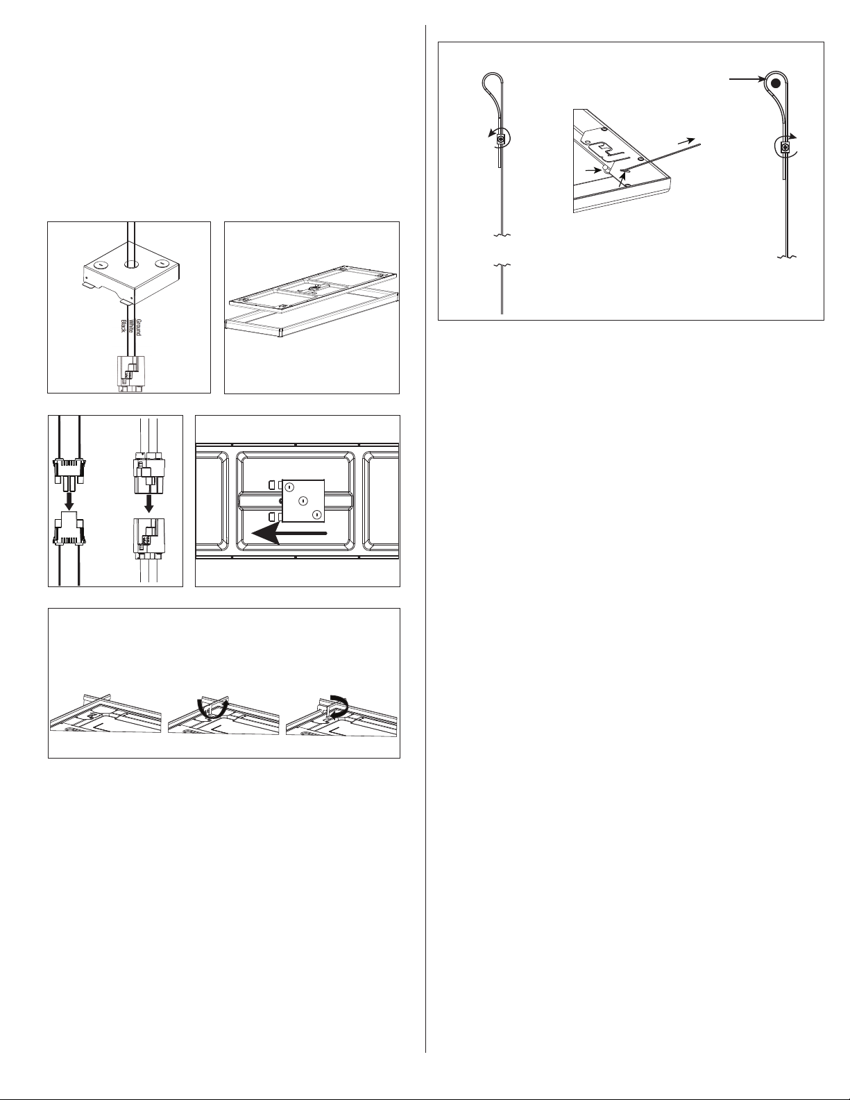
3. Locate the driver disconnect on the back side
of fixture and pull out the female half with no wires
attached (Fig.3).
4. Prepare the supply wires. Class I wiring only.
Minimum 90C supply wires.
A. Wiring must comply with all applicable electrical
codes.
B. Strip wire to 3/8” (9, 5 mm).
C. Grip black supply wire firmly and push conductor
into port marked with black circle and letter “B”
on the connector (Fig. 4).
D. Grip white supply wire firmly and push conductor
into port with white circle and letter “W” on the
connector (Fig. 4).
E. If using two port connector connect ground wire
using supplied wire nut (G). If using three port
connector grip ground wire firmly and push into
port with green circle on the connector (Fig. 4).
5. Pull the disconnect attached to supply wires through desired knockout hole on the
fixture JBOX cover (Fig.5).
Fig. 3
Two Port
Connector
1
or
Three Port
Connector
Connector
Fig. 1
Fig. 2
Fig. 4
Two Port
or
Three Port
Connector
Note: Fixture weighs approximately 11lbs. Ensure grid location is rated for fixture
weight before moving to next step. If unsure use cable to support fixture to appropriate
support beam above fixture. See cable Support Installation.
6. Place fixture in desired grid location (Fig. 6).
7. Fully reconnect the quick disconnect by pushing the mating ends together (Fig. 7).
Note: Dimming leads should be wired at this point for 0-10V dimming applications. See
installing dimmer instructions below.
8. Slide fixture JBOX cover to cover all wires on back of fixture ensuring the
disconnect and dimming wires are all completely inside fixture JBOX cover (Fig. 8).
9. Orient 4 tabs on back of fixture over T-GRID by bending tabs up 90 degrees
perpendicular to back of fixture. Next bend tabs 90 degrees towards T-GRID frame (Fig. 9).
10. Turn breaker on. Use wall switch to verify light turns on.
Fig. 5
Fig. 7
Fig.9
T-Grid Folding Tab Instructions
Step 1
Fig. 6
Fig. 8
Step 2
INSTALLING SUPPORT CABLES
1. Remove cable lock by loosening set screw and pulling cable lock off cable (Fig 10).
2. Slide cable through slot provide on back plate corner piece until the sphere bottoms out
against the slot (Fig 10).
3. Slide cable lock onto cable. Loop open end of cable around support beam and back
through cable lock (Fig 10).
4. Tighten cable lock set screw (Fig 10).
INSTALLING DIMMER
(For 0-10V Dimming)
• Using the wire termination provided on the dimming lead, combine the positive lead
from the dimmer with the positive lead (violet) connected to the dimming port (DIM +)
of the driver
• Combine the negative lead from the dimmer with the gray negative lead connected to
the (DIM -) dimming port of the driver using the wire termination that is fastened to the
end of the gray dimming lead
See Dimmer Compatibility http://www.eaton.com/content/public/en/lighting/brands/
metalux.html
Fig. 10
STEP 1
STEP 2
STEP 3
Support Beam
5-YEAR LIMITED WARRANTY
THE FOLLOWING WARRANTY IS EXCLUSIVE AND IN LIEU OF ALL OTHER WARRANTIES,
WHETHER EXPRESS, IMPLIED OR STATUTORY INCLUDING, BUT NOT LIMITED TO, ANY
WARRANTY OF MERCHANTABILITY OR FITNESS FOR ANY PARTICULAR PURPOSE.
Eaton warrants to customers that, for a period of five years from the date of purchase,
Eaton products will be free from defects in materials and workmanship. The obligation of
Eaton under this warranty is expressly limited to the provision of replacement products. This
warranty is extended only to the original purchaser of the product. A purchaser’s receipt or
other proof of date of original purchase acceptable to Eaton. This is required before warranty
performance shall be rendered. This warranty does not apply to Eaton products that have been
altered or repaired that have been subjected to neglect, abuse, misuse or accident (including
shipping damages). This warranty does not apply to products not manufactured by Eaton
which have been supplied, installed, and/or used in conjunction with Eaton products. Damage
to the product caused by replacement bulbs or corrosion or discoloration of brass components
are not covered by this warranty.
LIMITATION OF LIABILITY:
IN NO EVENT SHALL EATON BE LIABLE FOR SPECIAL, INDIRECT, INCIDENTAL, OR
CONSEQUENTIAL DAMAGES (REGARDLESS OF THE FORM OF ACTION, WHETHER IN CONTRACT,
STRICT LIABILITY, OR IN TORT INCLUDING NEGLIGENCE), NOR FOR LOST PROFITS; NOR SHALL
THE LIABILITY OF EATON FOR ANY CLAIMS OR DAMAGE ARISING OUT OF OR CONNECTED
WITH THESE TERMS OR THE MANUFACTURE, SALE, DELIVERY, USE, MAINTENANCE, REPAIR OR
MODIFICATION OF EATON PRODUCTS, OR SUPPLY OF ANY REPLACEMENT PARTS THEREFORE,
EXCEED THE PURCHASE PRICE OF EATON PRODUCTS GIVING RISE TO A CLAIM. NO LABOR
CHARGES WILL BE ACCEPTED TO REMOVE OR INSTALL FIXTURES.
To obtain warranty service, please contact Eaton, at 1-800-334-6871, press option 2 for
Customer Service, or via e-mail Consumer-Products@eaton.com and include the following
information:
• Name, address and telephone number
• Date and place of purchase
• Catalog and quantity purchase
• Detailed description of problem
All returned products must be accompanied by a Return Goods Authorization Number issued
by the Company and must be returned freight prepaid. Any product received without a Return
Goods Authorization Number from the Company will be refused. Eaton is not responsible for
merchandise damaged in transit. Repaired or replaced products shall be subject to the terms
of this warranty and are inspected when packed. Evident or concealed damage that is made
in transit should be reported at once to the carrier making the delivery and a claim filed
with them.
Reproductions of this document without prior written approval of Eaton are strictly prohibited.
For assistance, call 1-800-334-6871 or e-mail us at ConsumerProducts@eaton.com
Printed in China
2
 Loading...