

Eaton MEMSHIELD 3 EPBN1SPD123, MEMSHIELD 3 EPBN1SPD1234 Installation Instructions Manual
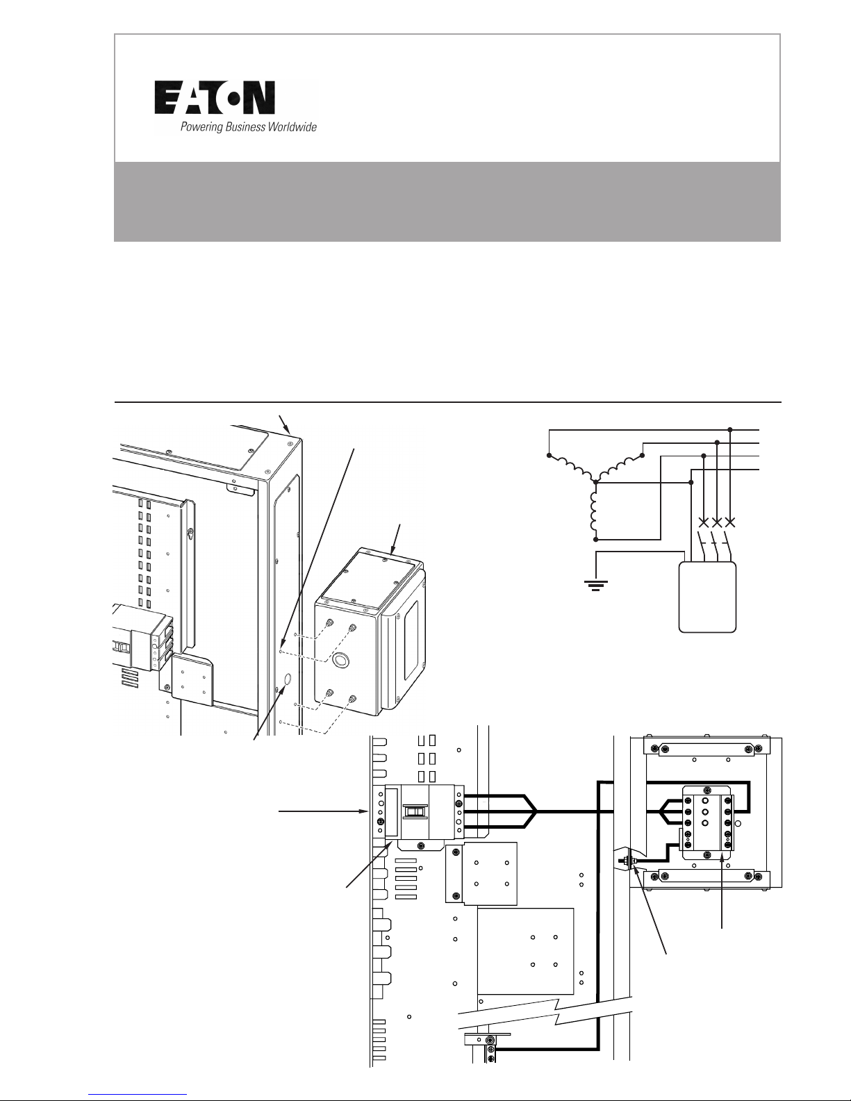
NEUTRAL
L1
L2
L3
Enclosure fixing screw
NOTE:
SPD can be
mounted on the left
or right hand side of
the panelboard.
Right hand side shown
When mounting on LH side
rotate SPD enclosure 180
0
and ensure phase cables are
connected to correct terminals.
EARTH
Lowest RH
outgoing way for
63A size MCCB
Supplied
63A NZM1 TP MCCB
SPD
L1
L2
L3
IMPORTANT NOTES
1. This product should be installed, commissioned and maintained by or under the supervision of a competent electrician
in accordance with current electrical engineering Codes of Practice, Regulations for the Electrical equipment of
Buildings (BS7671), CDM2007 - Construction (Design and Management) Regulations 2007, HSG150 - Health and
Safety in Construction, Statutory requirements and any Specific instruction issued by the Company.
2. After completing the installation and testing of this product it is essential that this leaflet is drawn to the attention of
the person responsible for its future operation and maintenance, and is at all times available for ready reference.
3. These notes assume throughout that the product is disconnected from the supply. It is essential that this is done
before any work is carried out.
4. These Panelboards are only designed for use with Eaton MCCBs. Failure to comply will result in invalid warranty and
certification.
FIG.2. Cabling
MEMSHIELD 3 PANELBOARD SURGE PROTECTION DEVICE
INSTALLATION INSTRUCTIONS FOR EPBN1SPD123 AND EPBN1SPD1234
Instruction leaflet LT1215 (7/11)
FIG.1. Panelboard
Drill 1 x 27mm Dia.Hole
Drill
4 x 6mm
Dia.Holes
SPD
Enclosure
Wiring Diagram
NEUTRAL
EARTH
L1
L2
L3
N
SPD
MCCB

BEFORE INSTALLATION:
A. Verify that the system is wired in a Three Phase Star configuration and that the voltage rating of
the system matches the voltage rating of the SPD as shown on label.
If Neutral to Earth voltage is greater than 5 VAC, then a problem may exist in the electrical
system. The SPD may be installed; however, a qualified person should be consulted to
correct the problem.
B. The SPD must be connected to the Memshield 3 Panelboard via the Triple Pole 63A MCCB supplied.
NOTE: If the SPD is to be used in conjunction with equipment other than a Series G Panelboard,
the SPD must be connected via an appropriate protective device for the location of the
installation.
NOTE FOR CLEAN EARTH:
If the system utilises a clean earth, the green/yellow earth wire must be connected to the clean
earth bar.
INSTALLATION INSTRUCTIONS:
1. ISOLATE INCOMING ELECTRICAL SUPPLY.
2. SPD MOUNTING POSITION
The SPD should be mounted for the shortest and straightest possible wire installation from
the SPD to the MCCB and Earth/Neutral Busbar. It is strongly recommended that the FIRST
outgoing NZM1 way be used to minimise the connecting wire length.
Excessive wire length and sharp bends degrade SPD performance: therefore, avoid excessive
wire length and sharp bends when at all possible.
3. ASSEMBLE SPD ENCLOSURE TO STANDARD PANELBOARD (as shown in Fig.1.).
• Position the SPD enclosure on either the left or right side of the Board and align it so that the 27.0 mm
Dia hole is approximately in line with the centre of the lowest outgoing way for a 63A size MCCB.
• Using the SPD enclosure as a template, mark position of holes onto the Panelboard side plate.
• With care, drill 4 holes 6mm dia into the Panelboard side plate and 1 hole 27.0 mm dia in line with
the middle of the MCCB. Fig.1.
• Remove burrs and ensure both enclosures are free of debris.
• Bolt both enclosures in position, ensure that the nuts and shakeproof washers are inside the
Panelboard. Insert grommet in 27mm hole.
4. CABLE SPD. (As shown in Fig.2).
• Keep the wire(s) as short as possible for optimum SPD performance.
• Connect the EARTH wire to the nearest bolt (see Fig.2.).
• Refer to the NOTE for systems utilising the clean earth.
• Connect the NEUTRAL wire to the Neutral Busbar.
• Connect Phase wire to the MCCB at L1, L2 & L3.
• Tie wrap all cables together for optimum SPD performance.
5. Energise the System.
• For the SPD ‘EPBN1SPD123’ the red Indicator should remain locked in position.
If the red indicator POPS UP, de-energise and contact the Technical Services department.
• For the SPD ‘EPBN1SPD1234’ the Indicator should remain green.
If the indicator turns RED, de-energise and contact the Technical Services department.
(See below).
Warning Intellectual Property Rights
Eaton wishes to make it clear that it owns intellectual property rights in the
product which it manufactures (whether or not listed in this leaflet) and that
it will take legal action against any party found to be manufacturing, using,
or selling any article which infringes the company’s intellectual property. All
marks in this document identified with an R symbol or a TM symbol adjacent
to the mark are trademarks of Eaton.
2004 Eaton Electric Limited.
All rights reserved.
C
The use to which this product is put and its place of installation is outside our
control. Particular care should therefore be taken to follow the instructions given
here and to ensure their continued availability in conjunction with the use of the
product.
No responsibility can be accepted by us if these instructions are disregarded.
Further copies of these instructions and information concerning the installation
and proper use of this product can be obtained by contacting the:
Technical Services Department
Eaton Electric Limited, Reddings Lane, Tyseley, Birmingham B11 3EZ.
Tel: +44(0)8700 545 333, Fax: +44(0)8700 540 333
Tel: +44(0)121 685 2100, Fax: +44(0)121 706 2012
email: ukcommorders@eaton.com
 Loading...