

Eaton MDS-408, MDN-508, MDS-508, MDS-808, MDS-608 Instructions For Installation, Operation And Maintenance
...
Double-wide Fixed
Standard Frame Fixed
Narrow Frame Fixed
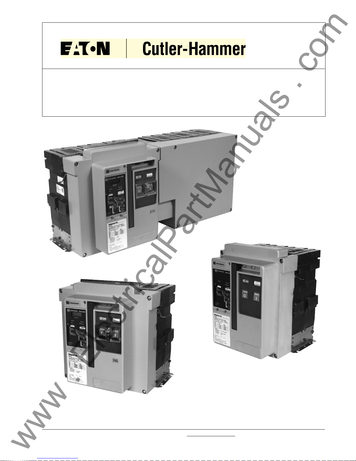
Instructions for Installation, Operation and Maintenance of
Magnum DS, DSX and DSL Low Voltage Power Circuit Breakers
I.B. 2C12060H08 Supersedes I.B. 2C12060H07 dated April 2005
Effective May 2006
IB2C12060H08
For more information visit: www.EatonElectrical.com
www . ElectricalPartManuals . com

www . ElectricalPartManuals . com

Instruction Book
Page iii
Effective: May 2006
I.B. 2C12060H08
For more information visit: www.EatonElectrical.com
For application information, consult Cutler-Hammer or
see applicable Product Guides, Technical Documents,
Application Publications and/or Industry Standards.
SAFETY
All safety codes, safety standards and/or regulations
must be strictly observed in the installation, operation
and maintenance of this equipment.
THE WARNINGS AND CAUTIONS INCLUDED AS
PART OF THE PROCEDURAL STEPS IN THIS MANUAL ARE FOR PERSONNEL SAFETY AND PROTECTION OF EQUIPMENT FROM DAMAGE. AN EXAMPLE OF A TYPICAL WARNING LABEL HEADING IS
SHOWN ABOVE TO FAMILIARIZE PERSONNEL
WITH THE STYLE OF PRESENTATION. THIS WILL
HELP TO INSURE THAT PERSONNEL ARE ALERT
TO WARNINGS. IN ADDITION, CAUTIONS ARE ALL
UPPER CASE AND BOLDFACE.
PURPOSE
This instruction manual is expressly intended to cover
the installation, operation and maintenance of Magnum
DS (MDS), DSX (MDSX) and Magnum DSL (MDSL)
Power Circuit Breakers. These circuit breakers may be
supplied as part of complete switchboard assemblies or
as separate components. This manual applies only to
the circuit breaker and (if drawout) it’s mating cassette.
The Magnum DSL circuit breaker can only be supplied
as a drawout device. In the case of fixed versions of
Magnum DS circuit breakers, certain sections of this
manual, referring to such items as position interlocks
and the drawout mechanism, will not apply.
Trip units associated with Magnum DS, DSX and DSL
Power Circuit Breakers will be addressed in a general
manner in this manual. Specific trip unit details and
time-current characteristic curves are covered in separate documents specific to the trip units.
Magnum DS, DSX and DSL circuit breaker accessory
items are discussed briefly in this manual. Field installation instructions for such items, however, are covered in
individual instruction leaflets specific to the accessory.
This information is also available from the CutlerHammer website at www.EatonElectrical.com
All possible contingencies which may arise during installation operation or maintenance, and all details and variations
of this equipment do not purport to be covered by these instructions. If further information is desired by purchaser
regarding his particular installation, operation or maintenance of particular equipment, contact the local CutlerHammer Inc. representative.
!
WARNING
www . ElectricalPartManuals . com

Instruction Book
Page iv
Effective: May 2006
I.B. 2C12060H08
For more information visit: www.EatonElectrical.com
TABLE OF CONTENTS
SECTION 1: INTRODUCTION PAGE
1-1 General Information.............................................................................................................................................1
1-2 Safety Features ...................................................................................................................................................2
1-3 Safety Practices ..................................................................................................................................................2
1-4 Qualified Personnel .............................................................................................................................................3
1-5 Other Publications and Documentation...............................................................................................................3
SECTION 2: RECEIVING, HANDLING AND INSTALLATION
2-1 General Information.............................................................................................................................................4
2-2 Suggested Tools .................................................................................................................................................4
2-3 Unpacking Circuit Breaker...................................................................................................................................4
2-3.1 Storing Circuit Breaker ...........................................................................................................................4
2-4 Lifting Circuit Breaker ..........................................................................................................................................5
2-5 Circuit Breaker Inspection ...................................................................................................................................6
2-6 Installing Drawout Circuit Breaker .......................................................................................................................6
2-6.1 Rejection Interlocks ................................................................................................................................6
2-6.2 Circuit Breaker Positioning .....................................................................................................................7
2-6.3 Levering Circuit Breaker .........................................................................................................................9
2-7 Fixed Circuit Breaker.........................................................................................................................................10
2-8 Circuit Breaker Operation..................................................................................................................................10
SECTION 3: CIRCUIT BREAKER DESCRIPTION AND OPERATION
3-1 Introduction........................................................................................................................................................11
3-1.1 MDSL Application/Operation ................................................................................................................15
3-2 Basic Circuit Breaker Assembly ........................................................................................................................15
3-3 Pole Units ..........................................................................................................................................................15
3-3.1 Primary Moving Contacts .....................................................................................................................16
3-3.2 Primary Stationary Contacts.................................................................................................................16
3-4 Operating Mechanism .......................................................................................................................................17
3-4.1 Manual Operation .................................................................................................................................17
3-4.2 Electrical Operation ..............................................................................................................................18
3-4.3 Anti-Pump Feature ...............................................................................................................................18
3-5 Arc Chambers ...................................................................................................................................................18
3-5.1 Arc Chute .............................................................................................................................................18
3-6 Electronic Tripping System................................................................................................................................19
3-6.1 Microprocessor-based Trip Unit ...........................................................................................................19
3-6.2 Rating Plug ...........................................................................................................................................21
3-6.3 Current Sensors ...................................................................................................................................21
3-6.4 Trip Actuator .........................................................................................................................................22
3-6.5 Mechanical Trip Flag ............................................................................................................................22
3-6.6 Making Current Release.......................................................................................................................22
3-6.7 High Instantaneous Trip Option (Magnum DS Only) ............................................................................22
3-6.8 Voltage Taps ........................................................................................................................................23
3-7 Secondary Contacts and Connection Diagrams ...............................................................................................23
3-7.1 Connection Diagrams ...........................................................................................................................24
www . ElectricalPartManuals . com

Instruction Book
Page v
Effective: May 2006
I.B. 2C12060H08
For more information visit: www.EatonElectrical.com
PAGE
3-8 Accessory Devices ............................................................................................................................................46
3-8.1 Plug-In Electrical Accessories ..............................................................................................................46
3-8.2 Internal Electrical Accessories .............................................................................................................48
3-8.3 Mechanical Accessories .......................................................................................................................50
3-9 MDSL Limiters/Blown Limiter Indication............................................................................................................53
3-9.1 MDSL Current Limiters .........................................................................................................................53
3-9.2 Blown Limiter Sensing ..........................................................................................................................53
SECTION 4: DRAWOUT CIRCUIT BREAKER AND CASSETTE
4-1 General .............................................................................................................................................................55
4-1.1 Drawout Cassette .................................................................................................................................55
4-2 Drawout Circuit Breaker Dimensions ................................................................................................................57
4-3 Drawout Cassette Dimensions ..........................................................................................................................57
SECTION 5: FIXED CIRCUIT BREAKER
5-1 General .............................................................................................................................................................59
5-2 Fixed Circuit Breaker Dimensions .....................................................................................................................59
SECTION 6: INSPECTION AND MAINTENANCE
6-1 General .............................................................................................................................................................60
6-2 General Cleaning Recommendations ...............................................................................................................60
6-3 When to Inspect ................................................................................................................................................60
6-4 What to Inspect .................................................................................................................................................61
6-4.1 Functional Field Testing .......................................................................................................................61
6-4.2 Arc Chute Inspection ............................................................................................................................62
6-4.3 Primary Contact Inspection ..................................................................................................................63
6-5 Circuit Breaker Modifications and Changes ......................................................................................................64
6-5.1 Rating Plug Replacement.....................................................................................................................64
6-5.2 Current Sensor Replacement ...............................................................................................................65
6-5.3 Current Limiter Replacement (MDSL) ..................................................................................................66
6-5.3.1 Replacing Type MA and MB Current Limiters ......................................................................................55
6-5.3.2 Replacing Type MD Current Limiters ...................................................................................................66
6-5.3.3 Replacing Type MD Current Limiters on MDSL20 Breakers................................................................66
SECTION 7: TROUBLESHOOTING
7-1 Introduction........................................................................................................................................................67
SECTION 8: RENEWAL PARTS
8-1 General .............................................................................................................................................................70
www . ElectricalPartManuals . com

Instruction Book
Page vi
Effective: May 2006
I.B. 2C12060H08
For more information visit: www.EatonElectrical.com
FIGURES
Figure Title Page
1-1 Magnum DS Family of Low Voltage Power Fixed and Drawout Circuit Breakers (800-5000 Amperes) ..1
1-2 Typical Magnum Nameplate ....................................................................................................................2
1-3 & 1-4 Sample Designation Examples ................................................................................................................3
1-5 Typical Magnum DSL (MDSL) Drawout Breaker with Integral Current Limiters ......................................3
2-1 Shipping Clamps for Drawout Circuit Breaker ..........................................................................................4
2-2 Magnum DS Circuit Breaker with Lifting Yoke Attached ..........................................................................5
2-3 Rear View Showing Current Sensor Rating Through Viewing Window ....................................................6
2-4 One Side of Drawout MDS Circuit Breaker Properly Seated on Extension Rail ......................................6
2-5 Cassette Rejection Interlock Pin Positioning/Installation ..........................................................................7
2-6 Remove Position ......................................................................................................................................8
2-7 Disconnect Position ..................................................................................................................................8
2-8 Test Position ............................................................................................................................................8
2-9 Connect Position ......................................................................................................................................9
2-10 Cassette Label Showing Disconnected, Test and Connected Position of Recessed Cover ....................9
2-11 Levering Position Indication ....................................................................................................................10
2-12 Typical Fixed Magnum DS Circuit Breaker ............................................................................................10
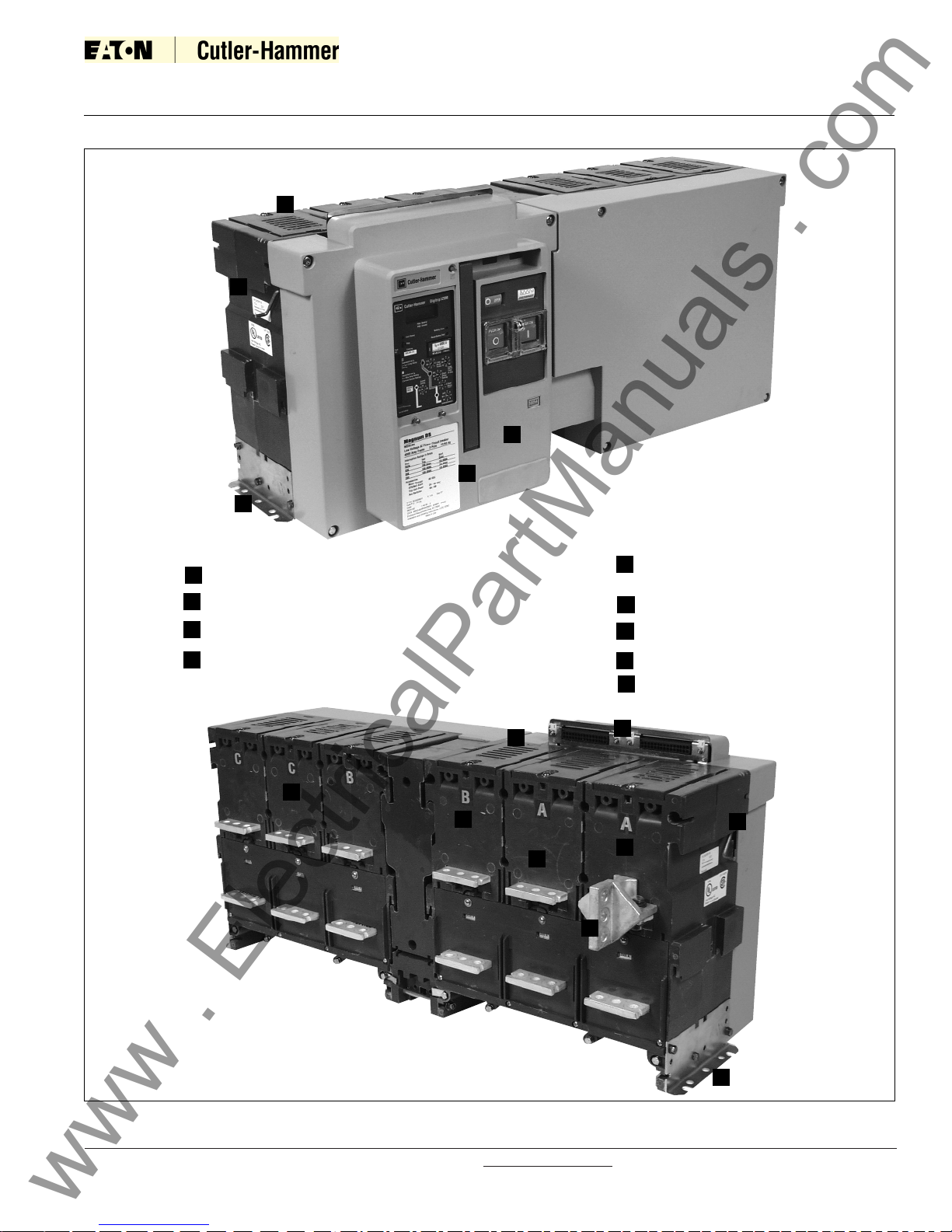
3-1 Typical MDS Drawout Circuit Breaker Features (Front and Rear Views) ..............................................11
3-2 Typical MDS Fixed Circuit Breaker Features (Front and Rear Views)....................................................12
3-3 Typical MDSL Drawout Circuit Breaker Features (Front and Rear Views) ............................................12
3-4 Typical Double-wide MDS Standard Frame Circuit Breaker Features (Front and Rear Views)..............13
3-5 Typical Magnum DS Drawout Circuit Breaker Front Cover ....................................................................14
3-6 Typical Magnum Construction (Right Side View)....................................................................................15
3-7 Features of Magnum Moving Conductor Assembly ................................................................................15
3-8 Narrow Frame (8-finger) Moving Conductor Assembly ..........................................................................16
3-9 Standard Frame (12-finger) Moving Conductor Assembly......................................................................16
3-10 Parital Cross-Sectional View (Shown in Closed Position) ......................................................................16
3-11 Electrically Operated Drawout MDS Circuit Breaker with Front Cover Removed ..................................17
3-12 Circuit Breaker Closing Springs Being Manually Charged......................................................................18
3-13 Electrical Motor Operator to Charge Closing Spring ..............................................................................18
3-14 Cross Section of Conductor and Arc Control System ............................................................................19
3-15 Integral Arc Runner as Viewed From Top of Arc Chamber
(Arc Chute Removed and Circuit Breaker Closed) ................................................................................19
3-16 Magnum Arc Plate Assembly ..................................................................................................................19
3-17 Pictorial Diagram of Typical Current Sensing, Processing and Tripping System....................................20
3-18 Digitrip RMS 1150 Programmable Trip Unit Installed in Magnum DS Circuit Breaker............................21
3-19 Hand Held Tester ....................................................................................................................................21
3-20 Replaceable Current Sensors Shown with Bottom Adapters and Cover Plate Removed ......................22
3-21 Line Side Voltage Tap for 1150 Trip Unit ................................................................................................23
3-22 Top View Secondary Connectors............................................................................................................23
3-23 Secondary Connector Protective Hood ..................................................................................................23
3-24 Cassette Mounted Secondary Wiring ......................................................................................................24
3-25 AMP Secondary Wiring Removal Tool.....................................................................................................24
3-26 Digitrip Connection Diagrams .................................................................................................................25
thru
3-46 Digitrip Connection Diagrams .................................................................................................................45
3-34 Through-the-Window Electrical Accessories ...........................................................................................46
3-35 Shunt Trip with Cutoff Switch...................................................................................................................46
3-36 Shunt Trip Switch Installed ......................................................................................................................46
3-37 Spring Release with Optional Latch Check Switch ..................................................................................47
3-38 Undervoltage Release Device .................................................................................................................47
www . ElectricalPartManuals . com

Instruction Book
Page vii
Effective: May 2006
I.B. 2C12060H08
For more information visit: www.EatonElectrical.com
Figure Title Page
3-39 Shunt Trip, Spring Release and Undervoltage Release Installed............................................................47
3-40 Auxiliary Switch (2A/2B)...........................................................................................................................48
3-41 Mechanical Trip Indicator with Associated Overcurrent Trip Switch ........................................................48
3-42 Motor Operator Kit ...................................................................................................................................49
3-43 Motor Operator Installed in Narrow Frame Circuit Breaker......................................................................49
3-44 Cover Mounted Key Lock and Operations Counter................................................................................. 50
3-45 Cassette Mounted Key Lock ....................................................................................................................50
3-46 ON-OFF Pushbutton Lockable Cover Plate.............................................................................................50
3-47 Safety Shutters in Closed Position...........................................................................................................51
3-48 Safety Shutters in Open Position .............................................................................................................51
3-49 Cell Switch (Drawout Position Indicator) Unmounted ..............................................................................51
3-50 Cell Switches Mounted on Cassette ........................................................................................................51
3-51 Door Escutcheon and Gasket ..................................................................................................................51
3-52 IP54 Waterproof Cover ............................................................................................................................52
3-53 Cassette-Mounted 2-Way Cable Interlock ...............................................................................................52
3-54 Magnum DSL Circuit Breaker (Side View)...............................................................................................53
3-55 Blow Fuse Indicator .................................................................................................................................53
4-1 Drawout Circuit Breaker in Cassette .......................................................................................................55
4-2 Drawout Circuit Breaker with Automatic Primary Disconnects ................................................................55
4-3 Drawout Cassette Features .....................................................................................................................56
4-4 Narrow Frame Cassette (Horizontal Terminals) ......................................................................................57
4-5 Standard Cassette (Vertical Terminals) ..................................................................................................57
4-6 Basic Cassette (Without Stabs) ...............................................................................................................57
4-7 Universal Cassette, 4-Pole (Flat Terminal Pads).....................................................................................57
4-8 Typical MDSL Standard Cassette (Front View) .......................................................................................58
4-9 Typical MDSL Standard Cassette (Rear View)........................................................................................58
5-1 Fixed Circuit Breaker with Available Vertical Adaptor..............................................................................59
6-1 Top Rear View of Circuit Breaker with One Arc Chute Removed............................................................62
6-2 Bottom View of Arc Chute........................................................................................................................62
6-3 Primary Contacts with Circuit Breaker Open (Not Used for Contact Wear Inspection) ...........................63
6-4 Contact Inspection Area with Circuit Breaker Open.................................................................................63
6-5 Use of Contact Wear Indicator with Circuit Breaker Closed ....................................................................64
6-6 Trip Unit Rating Plug Location .................................................................................................................64
6-7 Current Sensor Cover in Place Over Sensors .........................................................................................65
6-8 One Current Sensor Shown Removed and Disconnected.......................................................................65
6-9 MD Limiters Shown Mounted in Extension ..............................................................................................66
www . ElectricalPartManuals . com

Instruction Book
Page viii
Effective: May 2006
I.B. 2C12060H08
For more information visit: www.EatonElectrical.com
TABLES
Table Title Page
1.1 Magnum DS Ratings at 240, 480, 600 volts ..............................................................................................2
1.2 Magnum DSL Ratings at 600 volts ............................................................................................................3
2.1 Circuit Breaker Weights .............................................................................................................................5
2.2 Rejection Interlock Pin Locations ...............................................................................................................7
3.1 Magnum Digitrip Trip Units ......................................................................................................................20
3.2 Magnum DS Current Sensors and Matching Rating Plugs ......................................................................22
3.3 Shunt Trip Ratings ...................................................................................................................................46
3.4 Spring Release Ratings ...........................................................................................................................47
3.5 Undervoltage Release .............................................................................................................................48
3.6 Auxiliary Switch, Overcurrent Trip Switch and Cell Switch Contact Ratings............................................48
3.7 Motor Operator.........................................................................................................................................49
3.8 MDSL Integral Current Limiter Selection .................................................................................................54
6.1 Inspection Frequency...............................................................................................................................60
7.1 Circuit Breaker Troubleshooting Guide ....................................................................................................67
www . ElectricalPartManuals . com
SECTION 1: INTRODUCTION
1-1 GENERAL INFORMATION
The Magnum DS and DSX Power Circuit Breakers can
be fixed or drawout air circuit breakers utilizing an electronic tripping system. The Magnum DSL circuit breaker
utilizes the same tripping system, but is available only in
the drawout configuration. MDSL and MDSX versions
have current-limiting characteristics as indicated by the
“Current Limiting” badge on the front covers. All breakers are designed for use in both switchboard and metalenclosed switchgear assemblies having maximum voltages of 635 volts ac MDS type breakers, 600 volts ac for
MDSL type breakers, and 480 volts ac for MDSX type
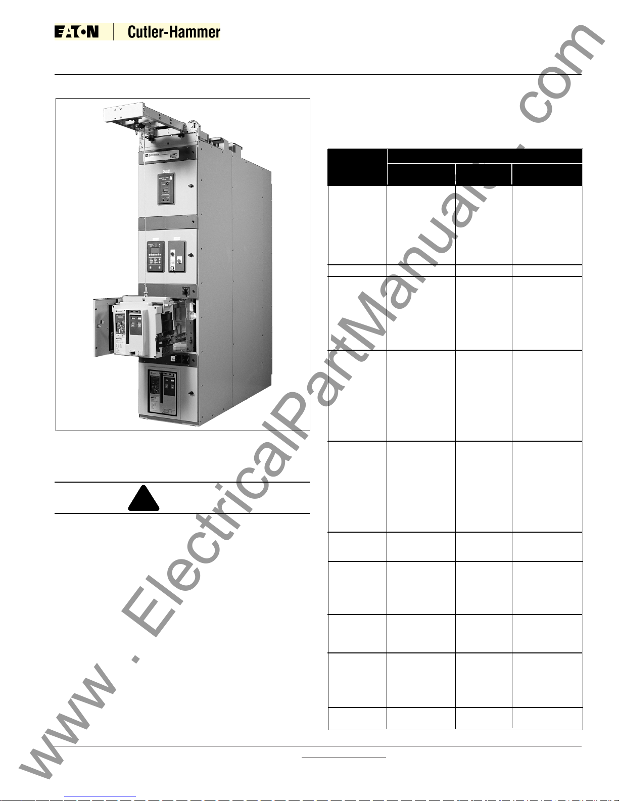
breakers. Magnum DS circuit breakers are available in
three physical frame sizes with continuous current ratings from 800 through 6000A. and interrupting capacities
from 42 kA to 200 kA. The three MDS physical frame
sizes have common height and depth dimensions, differing only in width (Figure 1-1). Magnum DSL circuit break-
ers are available in one frame size with continuous current ratings from 800 through 2000A and an interrupting
capacity up to 200,000A (Figure 1-5). Circuit breaker
nameplates provide complete rating information. All
Magnum DS, Magnum DSX, and Magnum DSL circuit
breakers are 100 percent rated, UL listed, and are built
and tested in an ISO 9002 certified facility to applicable
NEMA, ANSI, IEEE and UL standards (Tables 1.1 and
1.2, Figures 1-2, 1-3 and 1-4).
Magnum circuit breakers use a rigid frame housing of
engineered thermoset composite resins which has high
strength structural properties, excellent dielectric char-
acteristics and arc tracking resistance.
MDS, MDSX and MDSL drawout circuit breakers are a
through-the-door design having three breaker positions
with the compartment door closed (CONNECT, TEST,
DISCONNECT) and one position out of its compartment
on extension rails (REMOVE). The operating mechanism is a two-step stored energy mechanism, either
manually or electrically operated.
When withdrawn on captive compartment cassette
extension rails, MDS, MDSX and MDSL circuit breakers
can be inspected, accessory items added, and minor
maintenance performed. The inside of the compartment
can also be inspected with the circuit breaker on its
extension rails.
Please read and understand these instructions
before attempting to unpack, install, operate or
maintain this equipment. Study the breaker and its
mechanism carefully before attempting to operate it
on an energized circuit.
MAGNUM CIRCUIT BREAKERS SHOULD NOT
UNDER ANY CIRCUMSTANCES BE APPLIED OUTSIDE THEIR NAMEPLATE RATINGS. OPERATION
OUTSIDE OF THESE RATINGS COULD RESULT IN
DEATH, BODILY INJURY OR PROPERTY DAMAGE.
Instruction Book
Page 1
Effective: May 2006
I.B. 2C12060H08
For more information visit: www.EatonElectrical.com
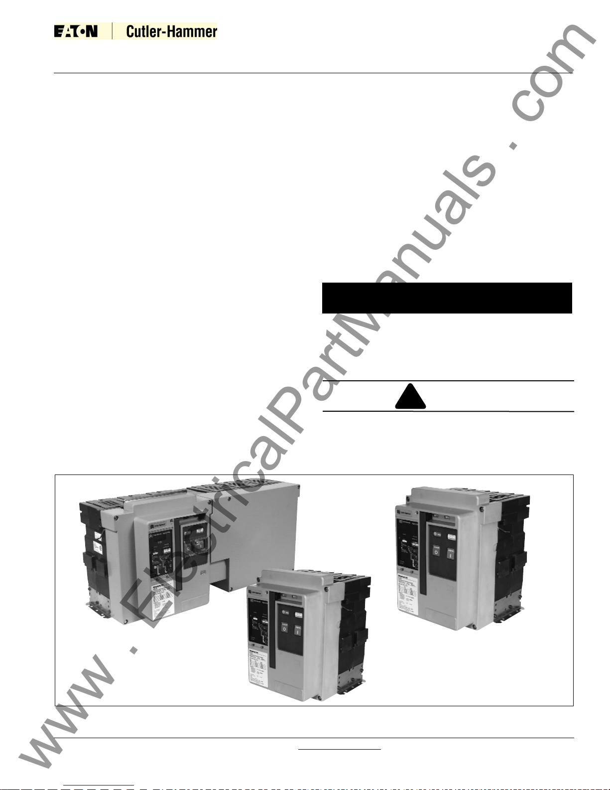
Figure 1-1 Family of Magnum DS (MDS) Low Voltage Power Fixed and Drawout Circuit Breakers (800-5000 Amperes)
NOTICE
Double-wide Fixed MDS
Narrow Frame Fixed MDS
Standard Frame Drawout MDS
!
WARNING
www . ElectricalPartManuals . com
Instruction Book
Page 2
Effective: May 2006
I.B. 2C12060H08
For more information visit: www.EatonElectrical.com
1-2 SAFETY FEATURES
Magnum DS, DSX and DSL circuit breakers and associated drawout equipment are manufactured with built-in
interlocks and safety related features. They are provided
to reduce hazards to operating personnel and provide
proper operating sequences.
MAGNUM DS, DSX AND DSL CIRCUIT BREAKERS
ARE ROBUST AND ARE PROVIDED WITH SAFETY
FEATURES. NEVERTHELESS, THE VOLTAGES,
CURRENTS AND POWER LEVELS AVAILABLE IN
AND AROUND THIS EQUIPMENT WHEN IT IS IN
OPERATION ARE EXTREMELY DANGEROUS AND
COULD BE FATAL. UNDER NO CIRCUMSTANCES
SHOULD INTERLOCKS AND OTHER SAFETY FEATURES BE MADE INOPERATIVE, AS THIS MAY
RESULT IN DEATH, BODILY INJURY OR PROPERTY
DAMAGE.
1-3 SAFETY PRACTICES
To protect personnel associated with the installation,
operation and maintenance of this equipment, the following practices must be followed:
Table 1.1 Magnum DS/DSX Ratings at 240, 480, 600 volts
!
WARNING
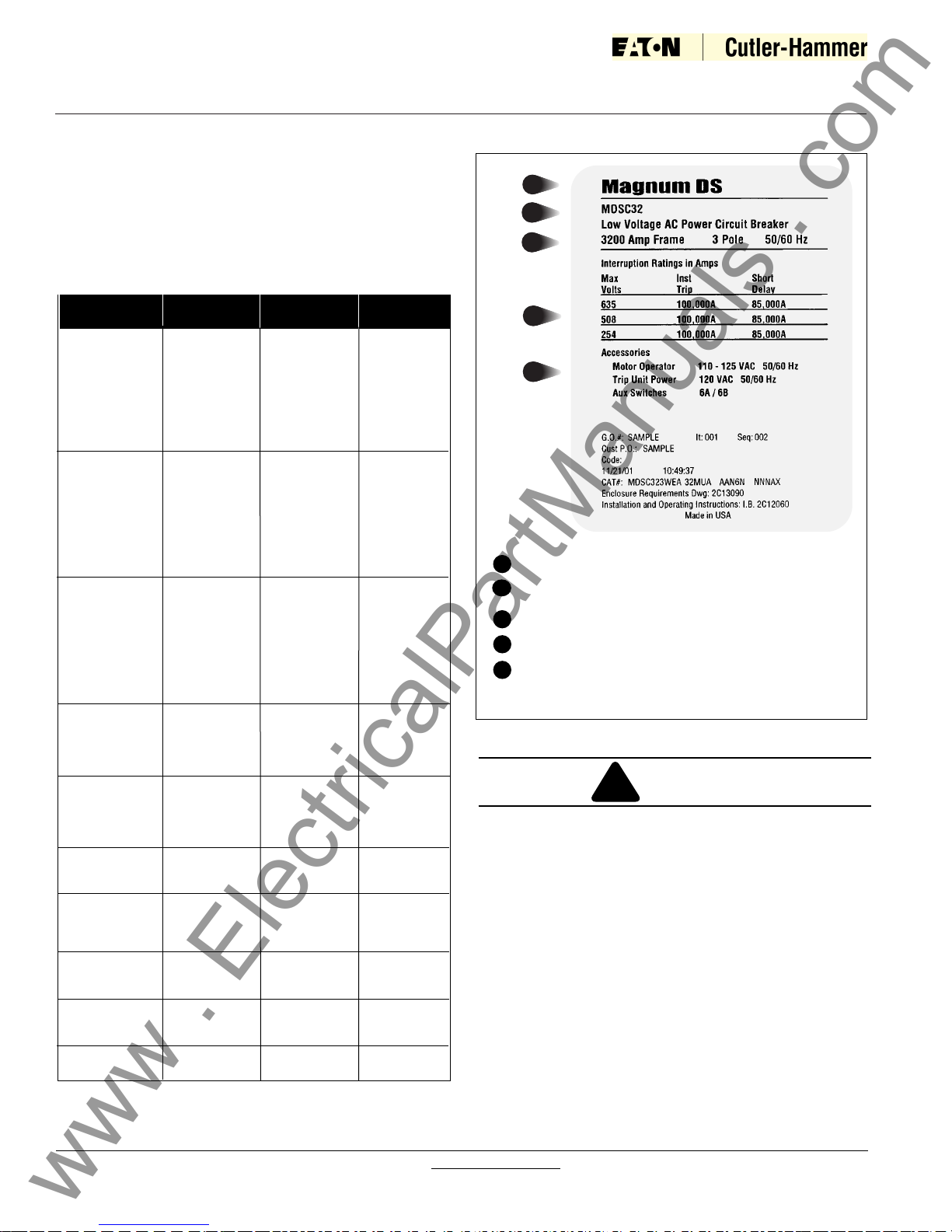
A
B
C
D
E
A
Figure 1-2 Typical Magnum DS (MDS) Nameplate
Low voltage power circuit breaker family name
Breaker family designation number
C
Breaker frame size in amperes
D
Interrupting capacity rating
E
Factory Equipped Accessories
Maximum Breaker Interrupting Short Time
Amperes Designation Rating Rating
800 MDN-408 42 kA 42 kA
MDN-508 50 kA 50 kA
MDN-608 65 kA 65 kA
MDS-X08 200 kA (240v, 480v.) 30 kA
MDS-408 42 kA 42 kA
MDS-508 50 kA 50 kA
MDS-608 65 kA 65 kA
MDS-808 85 kA 85 kA
MDS-C08 100 kA 85 kA
1200 MDN-412 42 kA 42 kA
MDN-512 50 kA 50 kA
MDN-612 65 kA 65 kA
MDS-X12 200 kA (240v, 480v.) 30 kA
MDS-412 42 kA 42 kA
MDS-512 50 kA 50 kA
MDS-612 65 kA 65 kA
MDS-812 85 kA 85 kA
MDS-C12 100 kA 85 kA
1600 MDN-416 42 kA 42 kA
MDN-516 50 kA 50 kA
MDN-616 65 kA 65 kA
MDS-X16 200 kA (240v, 480v.) 30 kA
MDS-416 42 kA 42 kA
MDS-516 50 kA 50 kA
MDS-616 65 kA 65 kA
MDS-816 85 kA 85 kA
MDS-C16 100 kA 85 kA
2000 MDS-520 50 kA 50 kA
MDS-X20 200 kA (240v, 480v.) 30 kA
MDS-620 65 kA 65 kA
MDS-820 85 kA 85 kA
MDS-C20 100 kA 85 kA
2500 MDS-525 50 kA 50 kA
MDS-X25 200 kA (240v, 480v.) 50 kA
MDS-625 65 kA 65 kA
MDS-825 85 kA 85 kA
MDS-C25 100 kA 85 kA
3000 MDS-630 65 kA 65 kA
MDS-830 85 kA 85 kA
MDS-C30 100 kA 85 kA
3200 MDS-X32, 3N 200 kA (240v, 480v.) 50 kA
MDS-632 65 kA 65 kA
MDS-832 85 kA 85 kA
MDS-C32 100 kA 85 kA
4000 MDS-X40 200 kA (240v, 480v.) 50 kA
MDS-840, 84N 85 kA 85 kA
MDS-C40, C4N 100 kA 100 kA
5000 MDS-X50 200 kA (240v, 480v.) 50 kA
MDS-850, 85N 85 kA 85 kA
MDS-C50, C5N 100 kA 100 kA
6000 MDS-860, 86N 85 kA 85 kA
MDS-C60, C6N 100 kA 100 kA
B
www . ElectricalPartManuals . com
M D S C 3 2
Instruction Book
Page 3
Effective: May 2006
I.B. 2C12060H08
For more information visit: www.EatonElectrical.com
1. Only qualified electrical personnel familiar with the
equipment, its operation and the associated hazards
should be permitted to work on the equipment.
Additionally, only qualified personnel should be permitted to install or operate the equipment.
2. Always be certain that the primary and secondary circuits are de-energized or the circuit breaker is
removed to a safe work location before attempting
any maintenance.
3. For maximum safety, only insert a completely assembled breaker into an energized cell.
4. Always ensure that drawout circuit breakers are in
one of their designed cell positions, such as Connect,
Test, Disconnect or Remove. A circuit breaker permitted to remain in an intermediate position could
result in control circuits being improperly connected
resulting in electrical failures.
1-4 QUALIFIED PERSONNEL
For the purpose of operating and maintaining low voltage power circuit breakers, a person should not be considered qualified if the individual is not thoroughly
trained in the operation of the circuit breaker and how it
interfaces with the assembly in which it is used. In addition, the individual should have knowledge of the connected loads.
For the purpose of installing and inspecting circuit
breakers and their associated assembly, a qualified person should also be trained with respect to the hazards
inherent to working with electricity and the proper way to
perform such work. The individual should be able to deenergize, clear and tag circuits in accordance with
established safety practices.
1-5 OTHER PUBLICATIONS AND
DOCUMENTATION
In addition to this instruction manual, other printed information and documentation is available and supplied as
appropriate. This additional information can include, but
not necessarily be limited to, an instruction manual for a
specific electronic trip unit, instruction leaflets for accessory items, renewal parts information, necessary dimensional drawings and a Product (application) Guide.
Specific reference documents associated with Magnum
DS, DSX and DSL circuit breakers are listed in a sepa-
rate document entitled Engineering Data TD01301004E
Figure 1-3 Typical Magnum DS Designation Example
Circuit Breaker
Type
MDS - Standard and
Double Wide Frames
MDN - Narrow Frame
Interrupting
Capacity
4 - 42,000
5 - 50,000
6 - 65,000
8 - 85,000
C - 100,000
E - 150,000
X - 200,000
Frame
Size
08 - 800 Amps
12 - 1200 Amps
16 - 1600 Amps
20 - 2000 Amps
25 - 2500 Amps
30 - 3000 Amps
32 - 3200 Amps
40 - 4000 Amps
50 - 5000 Amps
M D S L 0 8
Figure 1-4 Typical Magnum DSL Designation Example
Circuit Breaker
Type
MDSL- Standard Frame
with Integral Current
Limiters
Interrupting
Capacity
L - 200,000
Frame
Size
08 - 800 Amps
12 - 1200 Amps
16 - 1600 Amps
20 - 2000 Amps
Table 1.2 Magnum DSL Ratings at 600 Volts and Below
Breaker
Designation
Frame Size
Amperes
Max. Interrupting Rating, RMS Sym.
Amp., System Voltage 600 or Below
MDSL08
MDSL12
MDSL16
MDSL20
800
1200
1600
2000
200,000
200,000
200,000
200,000
Figure 1-5 Typical Magnum DSL(MDSL) Drawout
Circuit Breaker with Integral Current Limiters
www . ElectricalPartManuals . com
I.B. 2C12060H08
For more information visit: www.EatonElectrical.com
Instruction Book
Page 4
Effective: May 2006
Figure 2-1 Shipping Clamps for Drawout Circuit Breaker
SECTION 2: RECEIVING, HANDLING AND
INSTALLATION
2-1 GENERAL INFORMATION
Magnum DS, DSX and DSL Power Circuit Breakers,
when supplied as part of an assembly, may be shipped
already installed in their respective breaker compartments. Receiving and handling of this equipment is
addressed in an assembly instruction manual supplied
with the assembled equipment. This instruction manual
applies to only the circuit breakers.
2-2 SUGGESTED TOOLS
A large number of different tools are not required to
properly install and maintain Magnum DS, DSX and
DSL circuit breakers. The following tools are, however,
suggested:
• Flat blade screwdriver
• Phillips head screwdriver
• 3/8” socket (rachet) wrench
• 10 mm socket
• 17 mm socket
• Secondary wiring removal tool
2-3 UNPACKING CIRCUIT BREAKER
Before beginning to unpack new Magnum circuit breakers, read and understand these directions. Following the
directions will ensure that no damage is caused.
Shipping containers should be inspected for obvious
signs of rough handling and/or external damage
incurred during the transportation phase. Record any
observed damage for reporting to the transportation carrier and Cutler-Hammer, once the inspection is completed. All reports and claims should be as specific as possible and include the order number and other applicable
nameplate information.
Every effort is made to ensure that Magnum circuit
breakers arrive at their destination undamaged and
ready for installation. Care should be exercised, however, to protect the breakers from impact at all times. Do
not remove protective packaging until the breakers are
ready for inspection, testing and/or installation.
When ready to inspect and install a Magnum circuit
breaker, carefully remove the banding straps and lift off
the cardboard box. Remove any additional packing
material and internally packed documentation. The circuit breaker and/or cassette are mounted to a wooden
shipping pallet.
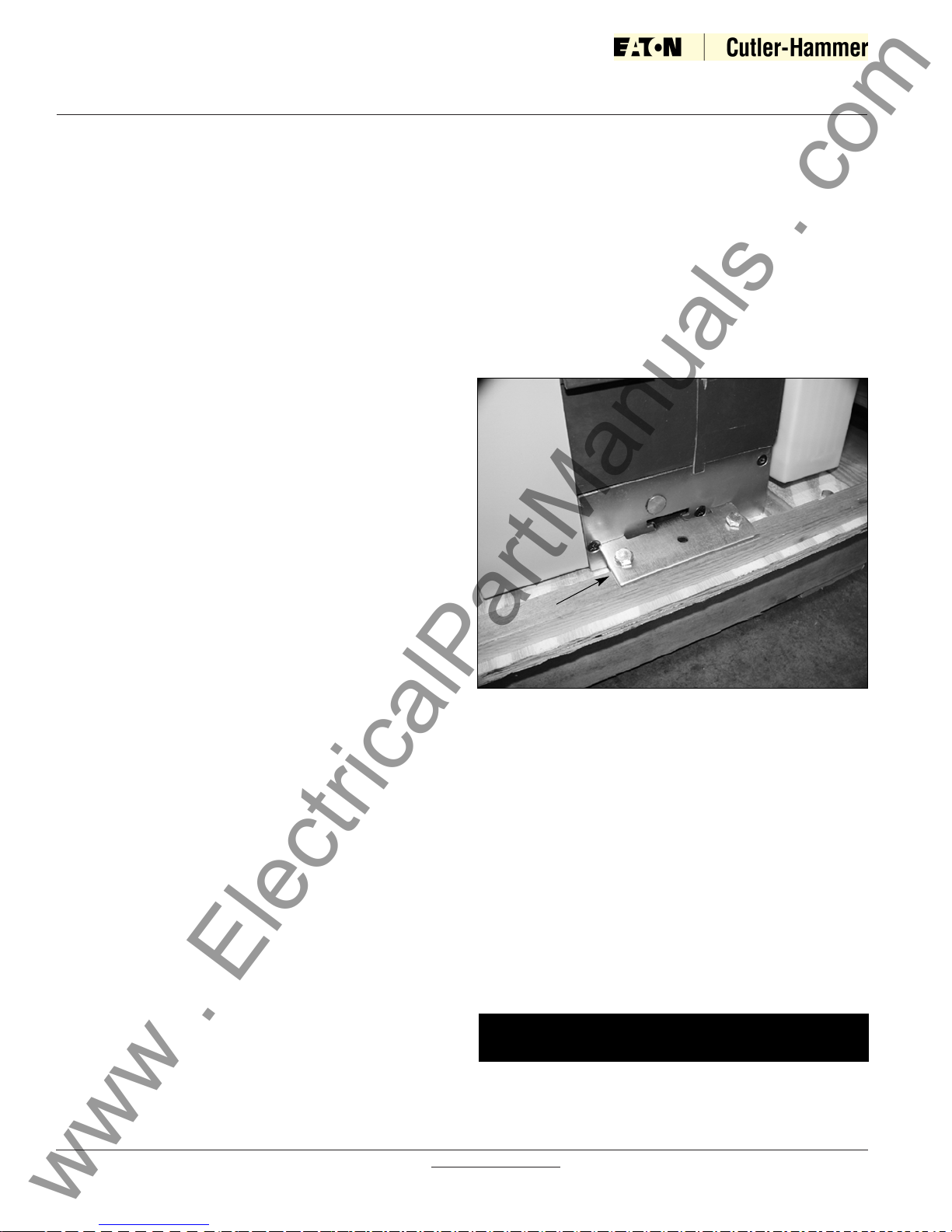
On drawout circuit breakers shipped without a cassette,
two shipping clamps hook into the breaker side plates
and are held to the pallet with 4 lag screws (Figure 2-1).
Remove the lag screws and clamps. Save the screws
and clamps for future shipment of the breaker. On
empty cassettes, remove the 4 or 5 lag screws and/or
machine screws which pass through the floorpan of the
cassette holding it to the wooden pallet. On drawout
breakers shipped in a cassette, first remove the breaker
from the cassette using the levering mechanism and
drawout rails. After the breaker is removed the machine
screws passing through the floorpan can be removed.
Shipping Clamp
On fixed breakers, remove the lag screws passing
through the mounting feet which hold the breaker to the
pallet.
Circuit breakers are designed to be easily lifted from
the wooden pallet using an appropriate lifting yoke and
overhead or portable lifting device (Figure 2-2).
2-3.1 STORING CIRCUIT BREAKER
If it is necessary to store a circuit breaker before installation, do so in its original shipping container. Keep the
circuit breaker in a clean dry place. Ensure there is
ample air circulation and heat, if necessary, to prevent
condensation. It is very important that the circuit breaker not be exposed to dirt or moisture.
A circuit breaker that has been stored for any
length of time should be operated a minimum of
five times before it is placed in service.
NOTICE
www . ElectricalPartManuals . com
I.B. 2C12060H08
For more information visit: www.EatonElectrical.com
Instruction Book
Page 5
Effective: May 2006
Breaker Weights (lbs)
Model Fixed Drawout Universal Cassette
3P 4P 3P 4P 3P 4P
MDN-408 95 120 107 136 61 70
MDN-508
MDN-608
MDN-412
MDN-512
MDN-612
MDN-416
MDN-516
MDN-616
MDS-408 114 141 130 161 117 123
MDS-508 118 146 138 172 117 123
MDS-608
MDS-412
MDS-512
MDS-612
MDS-416
MDS-516
MDS-616
MDS-520 128 160 155 194 117 123
MDS-620
MDS-808
MDS-812
MDS-816
MDS-820
MDS-C08
MDS-C12
MDS-C16
MDS-C20
MDS-525 150 190 189 240 123 150
MDS-625
MDS-630
MDS-632
MDS-825
MDS-830
MDS-832
MDS-C25
MDS-C30
MDS-C32
MDS-840, 84N 237 319 303 366 199 250
MDS-C40, C4N
MDS-E40, E4N
MDS-850, 85N 276 360 343 441 212 266
MDS-860, 86N
MDS-C50, C5N
MDS-C60, C6N
MDS-E50, E5N
MDS-E60, E6N
MDSL08 NA NA 180 NA 124 NA
MDSL12 200 124
MDSL16 200 124
MDSL20 215 131
MDS-X08 169 NA 210 NA 140 NA
MDS-X12
MDS-X16
MDS-X20
MDS-X25
MDS-X32
MDS-X40 279 NA 345 NA 210 NA
MDS-X50
Table 2.1 Basic Circuit Breaker Weights
2-4 LIFTING CIRCUIT BREAKER
DO NOT ATTEMPT TO LIFT CIRCUIT BREAKERS
WITH ORDINARY CRANE HOOKS, ROPES, CHAINS
OR OTHER SUCH DEVICES. FAILURE TO FOLLOW
THIS CAUTION COULD RESULT IN DAMAGE TO
VITAL PARTS SUCH AS ARC CHUTES, BARRIERS
AND WIRING OR THE ENTIRE CIRCUIT BREAKER.
To closely examine, install or just become more familiar
with the circuit breaker, carefully lift and place the circuit
breaker on a solid work surface capable of handling the
circuit breaker’s weight (Table 2.1) or on the captive
drawout extension rails of the breaker compartment
(Figure 2-2). This is accomplished by using the appropriate lifting yoke and lifter. The lifting yoke consists of
two steel hooks specially shaped to hook under the integral molded lifting handles on both sides of the circuit
breaker (Figure 3-1). Every effort should be made during lifting to minimize circuit breaker swing and tilt.
If the circuit breaker is to be lifted onto compartment
extension rails, follow the instructions in paragraph 2-6
entitled “Installing Drawout Circuit Breaker.”
!
CAUTION
Figure 2-2 Magnum DS Circuit Breaker with Lifting
Yoke Attached
www . ElectricalPartManuals . com
I.B. 2C12060H08
For more information visit: www.EatonElectrical.com
Instruction Book
Page 6
Effective: May 2006
2-5 CIRCUIT BREAKER INSPECTION
All circuit breakers, once removed from their shipping
containers, should be visually inspected for any obvious
damage.
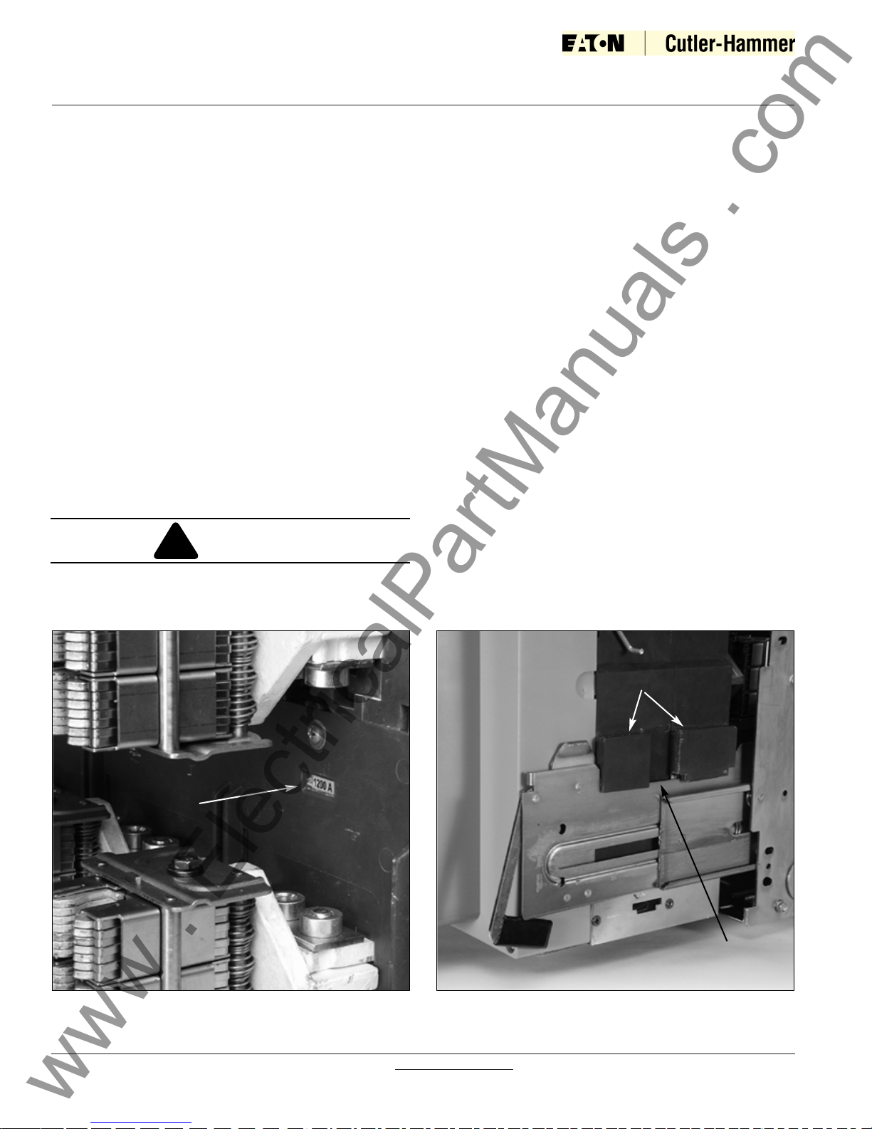
The current rating of the rating plug installed in the trip
unit should match the current rating of the sensors
mounted on the lower primary stabs of the circuit break
er. Check to make sure that this match exists. The rating plug rating can be viewed from the front of the circuit
breaker (Figure 3-4). The sensor rating can be viewed
through the viewing windows at the rear of the circuit
breaker (Figure 2-3). Sensors and rating plugs can be
easily changed as described in Section 6.
2-6 INSTALLING DRAWOUT CIRCUIT BREAKER
In structures equipped for drawout circuit breakers, a
bolted-in cassette with movable extension rails supports
the circuit breaker (Figures 2-2 and 2-4). The extension
rails must first be pulled all the way out. Once the rails
are fully extended, the circuit breaker can be carefully
placed on the extension rails.
IT IS IMPORTANT TO TAKE GREAT CARE WHEN
PLACING A DRAWOUT CIRCUIT BREAKER ON ITS
EXTENSION RAILS. IF THE CIRCUIT BREAKER IS
Figure 2-3 Rear View Showing Current Sensor Rating
Through Viewing Window
NOT PROPERLY SEATED ON THE EXTENSION
RAILS, IT COULD FALL FROM THE RAILS CAUSING
EQUIPMENT DAMAGE AND/OR BODILY INJURY.
Carefully lower the circuit breaker down onto the extension rails. Be certain that the circuit breaker’s four molded drawout rail supports are fully seated in the extension rail cutouts on both sides (Figure 2-4). Do not
remove the lifting yoke from the circuit breaker until
it is properly seated on the rails.
Once the circuit breaker is on the extension rails and the
lifting yoke is removed, proceed with the rest of the circuit breaker installation.
2-6.1 REJECTION INTERLOCKS
Within any one physical frame size Magnum type drawout circuit breakers come in a variety of continuous
current and interruption ratings, some of which are
incompatible with others. Double wide circuit breakers
also come with several phase sequence options which
are also incompatible. To prevent the insertion of circuit breakers with (1) inadequate interrupting capability,
(2) with physically incompatible primary disconnects or
(3) with an incompatible phase sequence, rejection
interlock key plates are provided on both the circuit
breaker and cassette. The key plate on the circuit
breaker is pre-assembled at the factory; but the cassette-side rejection plate and key pattern must be
assembled and installed by the switchboard builder.
!
CAUTION
Figure 2-4 One Side of Drawout MDS/MDSX Circuit
Breaker Properly Seated on Extension Rail
Molded Rail
Supports
Extension Rail
Cutout
www . ElectricalPartManuals . com
I.B. 2C12060H08
For more information visit: www.EatonElectrical.com
Instruction Book
Page 7
Effective: May 2006
DO NOT DISABLE REJECTION INTERLOCKS.
DOING SO AND USING A LOWER CAPACITY CIRCUIT BREAKER IN AN INCOMPATIBLE CASSETTE
COULD RESULT IN AN ELECTRICAL FAULT WHICH
COULD RESULT IN DEATH, BODILY INJURY
AND/OR EQUIPMENT DAMAGE.
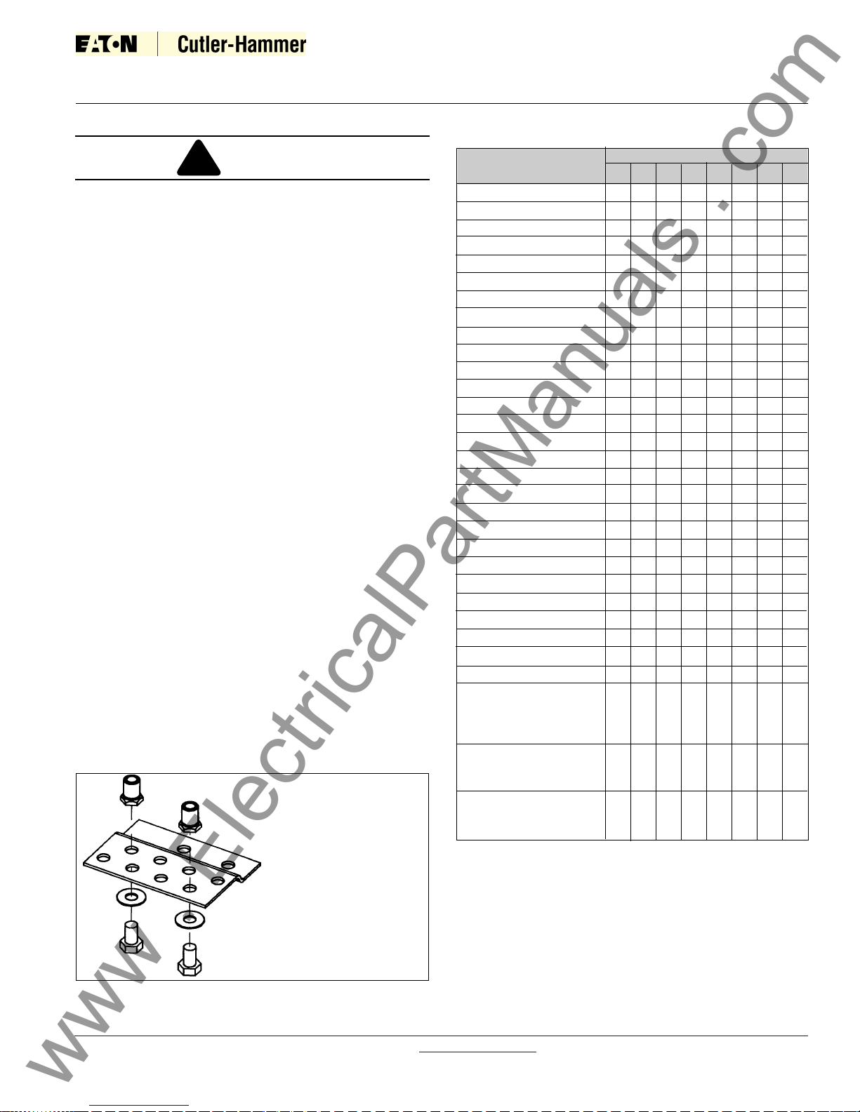
The rejection interlocks are steel pins in the floor of the
circuit breaker cassette. As the circuit breaker is
pushed into the structure, the mating pins on the bottom
of the circuit breaker move past a set of corresponding
pins in the cassette, if the circuit breaker and cassette
are compatible. If the circuit breaker and the cassette
are mismatched, the rejection pins will block the insertion of the circuit breaker into the cassette before the
levering-in mechanism is engaged.
Before attempting to push the circuit breaker into the
DISCONNECT position, compare the positioning of
rejection interlock pins in the cassette in keeping with
Table 2.2 and Figure 2-5 and the information supplied
on the circuit breaker’s nameplate. Proceed if the circuit
breaker and cassette are compatible.
2-6.2 CIRCUIT BREAKER POSITIONING
Magnum DS, DSX and DSL drawout circuit breakers
have four normal positions:
• REMOVE (Withdrawn) (Figure 2-6)
• DISCONNECT (Figure 2-7)
• TEST (Figure 2-8)
• CONNECT (Figure 2-9)
The REMOVE position is a position outside the compartment on the cassette’s drawout rails where the circuit breaker is not engaged with the levering mecha
!
CAUTION
nism. The DISCONNECT, TEST, and CONNECT, positions are reached by means of the levering mechanism.
With the breaker solidly positioned on the cassette’s
extension rails and the levering-in mechanism in the
DISCONNECT position, carefully and firmly push the
circuit breaker into the compartment as far as it will go.
The outer (recessed) portion of the circuit breaker face
plate should align with the GREEN target line (labelled
DISC) on the inside top left wall of the cassette (Figure
2-10).
Figure 2-5 Cassette Rejection Interlock Pin
Positioning/Installation
From Table 2.2, make a
pin location comparison.
Stop nuts should be
torqued to 8-10 Ft.-Lb.
Table 2.2 Rejection Interlock Pin Locations
1
2
3
4
5
6
7
8
Pin Locations
Cell For: 1 2 3 4 5 6 7 8
MDN-408, 412, 416
MDN-508, 512, 516
MDN-608, 612, 616
MDS-408, 412, 416
MDS-508, 512, 516, 520
MDS-608, 612, 616, 620
MDS-808, 812, 816, 820
MDS-C08, C12, C16, C20
MDS-525
MDS-625, 630, 632
MDS-825, 830, 832
MDS-C25, C30, C32
MDS-840
MDS-84N
MDS-C40
MDS-C4N
MDS-E40
MDS-E4N
MDS-850, 860
MDS-85N, 86N
MDS-C50, C60
MDS-C5N, C6N
MDS-E50, E60
MDS-E5N, E6N
MDSL08
MDSL12
MDSL16
MDSL20
MDS-X08
MSD-X12
MDS-X16
MDS-X20
MDS-X3N
MDS-X4N
MDS-X5N
MDS-X32
MDS-X40
MDS-X50
X
X
X
X
X
X
X
X
X
X
X
X
X
X
X
X
X
X
X
X
X
X
X
X
X
X
X
X
X
X
X
X
X
X
X
X
X
X
X
X
X
X
X
X
X
X
X
X
X
X
X
X
X
X
X
X
X
X
X
X
X
X
X-LG
X-LG
X-LG
X-LG
X-LG
X-LG
X-LG
X-LG
X-LG
X-LG
X
X
X
X
X
X
X
X
X
X
X
X
X
X
X
X
X
X
X
X
X
X
X
X
X
X
X
X
X
X
X
X
X
X
X
X
X
X
X
X
X
X
X
X
X
X
X
X
X
X
X
X
X
X
X
X
X
X
X
X
X
NOTE: X-LG IN TABLE 2.2 DENOTES LONG LENGTH STOP NUT 0.760 INCHES LONG
www . ElectricalPartManuals . com
I.B. 2C12060H08
For more information visit: www.EatonElectrical.com
Instruction Book
Effective: May 2006
Page 8
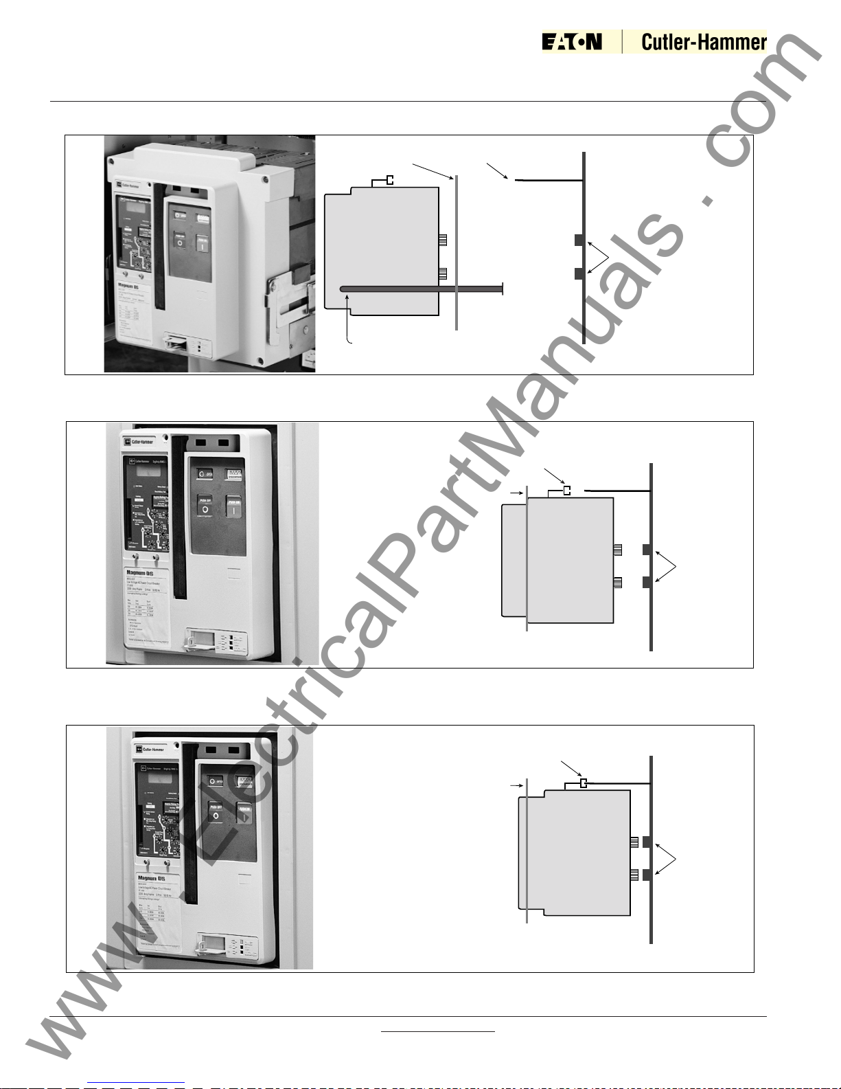
■ No Electrical Connections Made
■ Breaker On Extension Rails
■ Remove or Inspection Position
Circuit
Breaker
Side View
Secondary
Connection Not Made
Rear of
Compartment
Primary
Connections
Not Made
Compartment
Front Door
Circuit Breaker
Out of Compartment
On Extension Rails
Secondary
Connection
Not Made
Circuit
Breaker
Side View
Rear of
Compartment
Primary
Connections
Not Made
Compartment
Front Door
■ Only Ground Connection Made
■ Breaker Still Behind Door
■ Typical Storage Position
Circuit
Breaker
Side View
Secondary
Connection Made
Rear of
Compartment
Primary
Connections
Not Made
Compartment
Front Door
■ Breaker and Trip Unit Testing
■ Primary Connection Not Made
■ Secondary and Ground Connections Made
Figure 2-6 Remove Position
Figure 2-7 Disconnect Position
Figure 2-8 Test Position
www . ElectricalPartManuals . com

I.B. 2C12060H08
For more information visit: www.EatonElectrical.com
Instruction Book
Effective: May 2006
Page 9
Circuit
Breaker
Side View
Rear of
Compartment
Primary
Connections
Made
Secondary
Connection Made
Compartment
Front Door
■ Full Breaker Operation
■ Primary, Secondary and Ground Connections Made
■ Fully Racked into Cassette (Compartment)
Figure 2-9 Connect Position
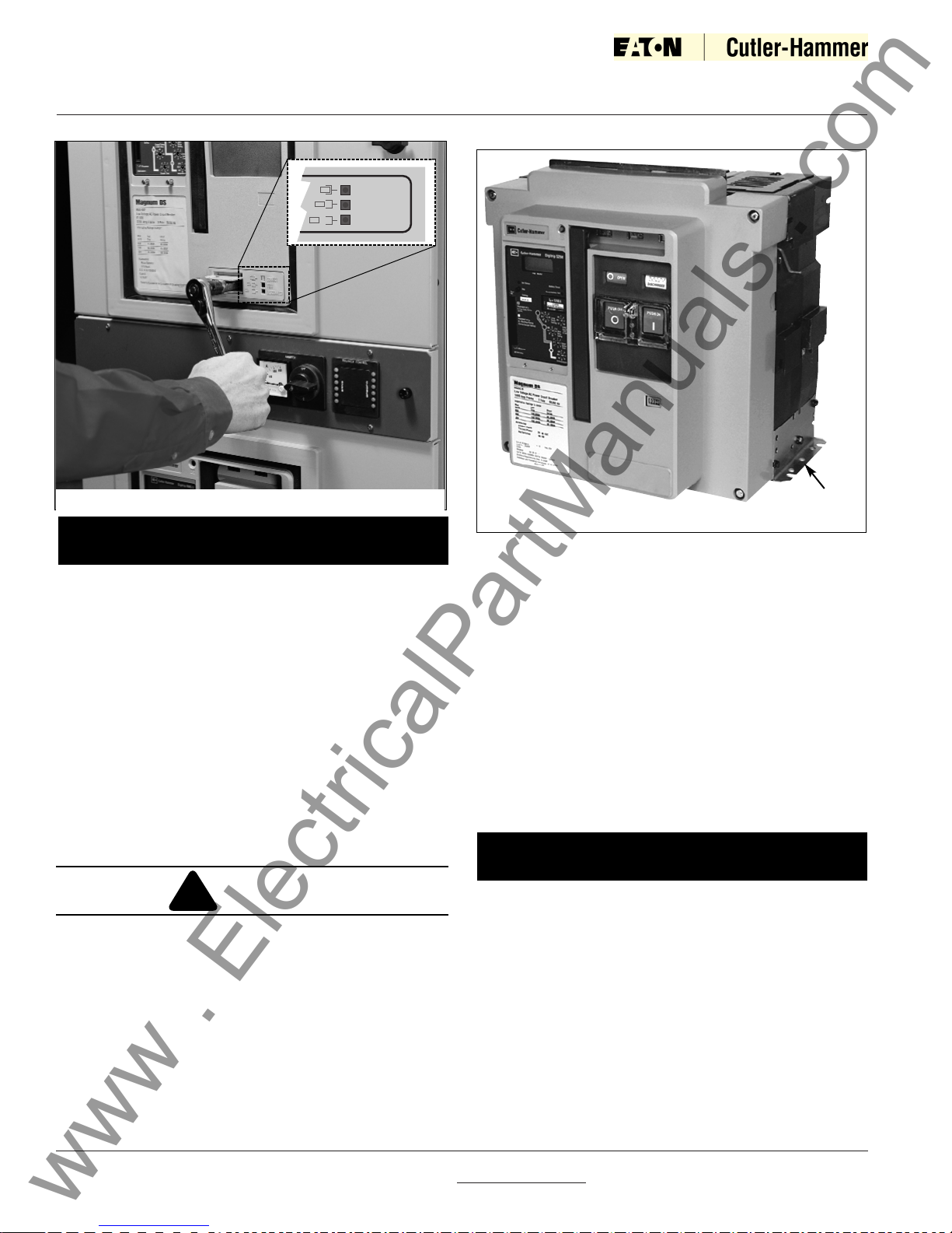
2-6.3 LEVERING CIRCUIT BREAKER
MAKE CERTAIN THAT THE CIRCUIT BREAKER IS
FULLY INSERTED INTO ITS COMPARTMENT
BEFORE ANY ATTEMPT IS MADE TO LEVER THE
CIRCUIT BREAKER. ATTEMPTING TO LEVER THE
CIRCUIT BREAKER IN BEFORE IT IS FULLY POSITIONED INSIDE ITS COMPARTMENT CAN RESULT
IN DAMAGE TO BOTH THE CIRCUIT BREAKER AND
THE COMPARTMENT.
The circuit breaker is now ready to be levered. With the
circuit breaker OPEN, the levering device access door
can be raised. The levering device is hand operated
using a standard 3/8” square drive and ratchet, which is
not provided (Figure 2-11). As long as the access door
is raised, the circuit breaker is held trip free. Begin by
rotating the levering-in screw to the full counterclockwise (DISCONNECT) position.
Close the compartment door and begin levering the
breaker into its different positions using a clockwise
ratcheting motion. When the circuit breaker is levered
fully to the DISCONNECT or CONNECT position the
levering shaft hits a hard stop; do not exceed 25 ft.lb. of
torque or the levering mechanism may be damaged.
The circuit breaker can be levered with the compartment door open or closed, but it is advisable to
close the door prior to levering. The position of the
circuit breaker within its compartment is indicated by
color coded position indicators (Red = Connect, Yellow
= Test, Green = Disconnect) (Figures 2-11 and 3-5). To
remove the circuit breaker from its compartment, follow
the procedure just described using a counterclockwise
ratcheting motion.
Figure 2-10 Cassette Label Showing Disconnected,
Test and Connected Position of Recessed Cover
!
CAUTION
www . ElectricalPartManuals . com
I.B. 2C12060H08
For more information visit:
www.EatonElectrical.com
Instruction Book
Effective: May 2006
Page 10
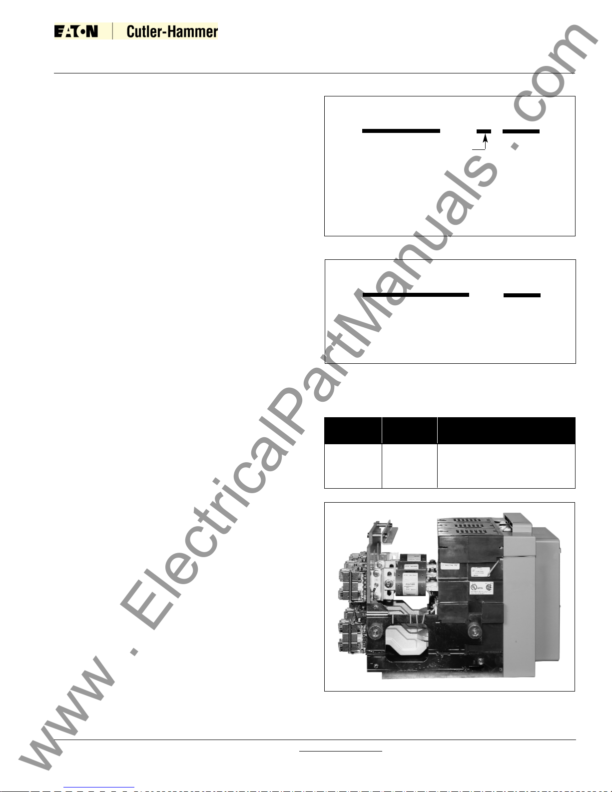
Figure 2-12 Typical Fixed Magnum DS Circuit Breaker
The circuit breaker mechanism is interlocked such
that charged closing springs are automatically discharged if the circuit breaker is levered into or out
of the cell. Discharge takes place between the DISCONNECT and TEST position.
2-7 FIXED CIRCUIT BREAKER
Magnum DS fixed type circuit breakers differ from the
drawout version in that it has no levering device, primary
disconnects and secondary disconnects (Figure 2-12).
In addition, a fixed circuit breaker does not have a standard feature to hold the breaker in a trip-free position.
To ensure the proper sequence of operation between
two or more circuit breakers, an optional key interlock is
mounted through the front panel (Figure 3-44).
FAILURE TO COMPLY WITH INSTALLATION OF
THE FIXED MOUNTED MDSX ARC HOOD ASSEMBLY COULD RESULT IN EQUIPMENT DAMAGE,
BODILY INJURY OR EVEN DEATH.
The MDSX fixed mounted breaker is shipped with an
included arc hood assembly. This assembly is required
to be installed on the top of the breaker prior to the unit
being placed in service.
Circuit breaker terminals have holes for making bolted
horizontal primary bus connections. Adapters are avail
Mounting
Foot
Figure 2-11 Levering Position Indication
NOTICE
able for making vertical primary bus connections.
Secondary connections can be made through standard
terminal blocks or a special connector compatible with
the drawout circuit breaker’s type secondary connector.
Both secondary connection devices are mounted at the
top front of the circuit breaker.
The fixed circuit breaker frame has two mounting feet,
one on each side, to permit the fixed circuit breaker to
be securely mounted. Each mounting foot has two slotted mounting holes which are used to bolt the circuit
breaker securely in place. Use either M10 or 3/8” bolts
for this purpose. Refer to the dimensional drawings
referred to in Section 5 (Fixed Circuit Breakers) for circuit breaker and bus stab dimensions.
Refer to the circuit breaker weights in Table 2.1 to
ensure that the panel on which a fixed circuit breaker is to be mounted is capable of supporting the
weight.
2-8 CIRCUIT BREAKER OPERATION
Circuit breakers should be operated manually and/or
electrically before they are put into service. This can be
done during the installation process or some later date
prior to start-up. To check circuit breaker operation, follow the operational procedures outlined in Section 3 for
both manually operated and electrically operated circuit
breakers.
NOTICE
!
WARNING
www . ElectricalPartManuals . com
CONNECT
CONNECT
TEST
TEST
DISCONNECT
DISCONNECT
I.B. 2C12060H08
For more information visit: www.EatonElectrical.com
Instruction Book
Page 11
Effective: May 2006
SECTION 3: CIRCUIT BREAKER
DESCRIPTION AND OPERATION
3-1 INTRODUCTION
Magnum DS (MDS), DSX (MDSX) circuit breakers are
available in both drawout and fixed mounting configurations (Figures 3-1 and 3-2). Magnum DSL (MDSL) circuit breakers with integral current limiters are available
only in a drawout configuration (Figure 3-3). A majority
of features are common to all configurations, and will be
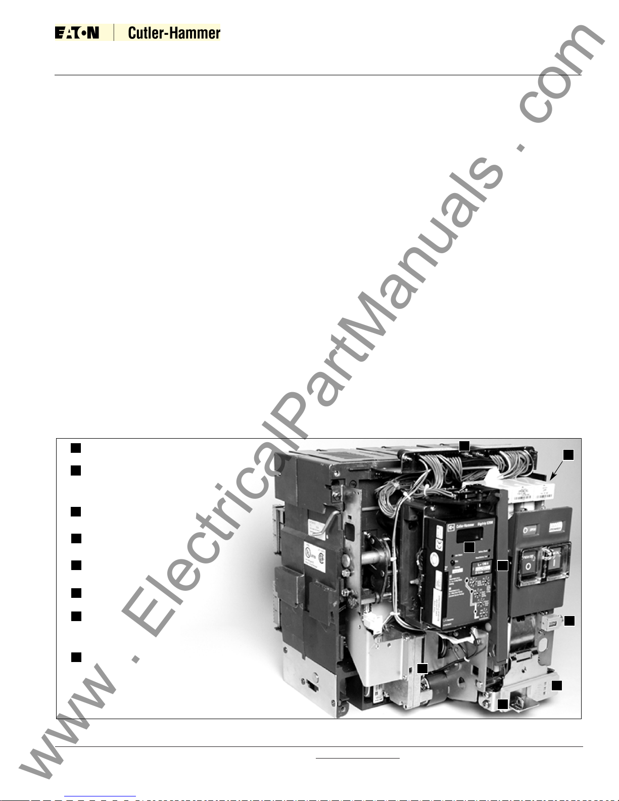
discussed in this section. The mounting features unique
to the drawout and fixed configurations will be covered
individually in Sections 4 and 5 respectively.
Controls and indicators for both drawout and fixed circuit
breakers are functionally grouped on the front of the circuit breaker. The front escutcheon (faceplate) is common for all Magnum frame sizes up through 5000
amperes.
Double Wide DS and DSX frame circuit breakers utilize
six (or eight) sets of rear primary connections; these circuit breakers are available from the factory with several
different phase sequences, distinguishable by the sixth
character in the model number. The phase sequence is
also labeled on the rear of the circuit breaker (Figure
3-4). For these DS and DSX drawout breakers, phase
sequence labels are also supplied with the cassette and
must be applied by the switchgear builder. Circuit brakers with different phase sequences are not interchangeable. DS and DSX drawout breakers with differing
phase sequence are prevented from insertion into the
cassette by properly assembled rejection key plates
(see section 2-6.2).
The Magnum DSL (MDSL) drawout circuit breaker is
available only in a 3-pole single wide standard configuration. The MDSL is a coordinated combination of a
standard Magnum DS circuit breaker and series connected current limiters. The primary purpose of the current limiters is to extend the interrupting rating of the
MDS circuit breaker up to 200,000 amperes.
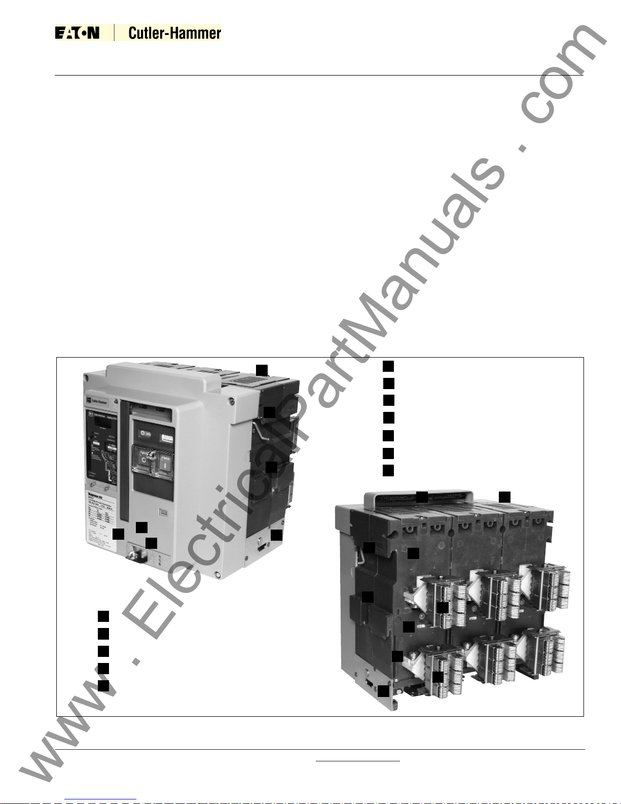
Figure 3-1 Typical MDS /MDSX Drawout Circuit Breaker Features (Front and Rear Views)
Baffled Arc Chute Cover
Secondary Disconnects (Contacts)
Faceplate (Front Cover)
Drawout Rail Supports
Integral Lifting Handle
5
2
1
6
7
9
4
3
8
10
Primary Disconnect Finger Cluster
Arc Chamber
Primary Vertical Adapter
Sensor Rating Viewing Window
Levering Device Bearing Plate
Padlockable Levering Device Access Door
Circuit Breaker Nameplate
11
12
1
12
3
4
4
5
5
6
6
7
8
9
10
10
11
12
www . ElectricalPartManuals . com
I.B. 2C12060H08
For more information visit: www.EatonElectrical.com
Instruction Book
Page 12
Effective: May 2006
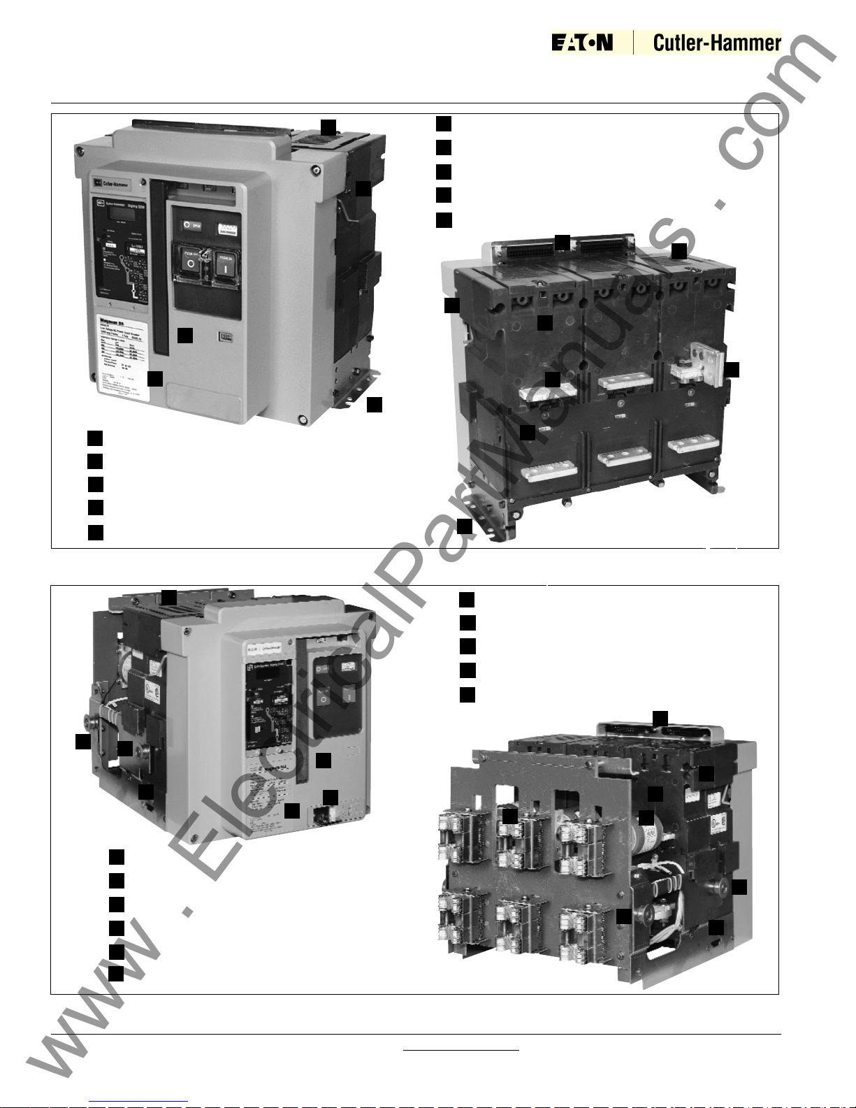
Figure 3-2 Typical MDS/MDSX Fixed Circuit Breaker Features (Front and Rear Views) (MDSX shown without
required arc hood)
Baffled Arc Chute Cover
Secondary Disconnect
Faceplate (Front Cover)
Integral Lifting Handle
5
2
4
3
Fixed Horizontal Primary Terminal
Fixed Primary Terminal (with optional Vertical Adapter)
Arc Chamber
Sensor Rating Viewing Window
Mounting Foot
6
7
8
9
10
1
1
2
3
4
4
5
6
7
8
9
9
10
Figure 3-3 Typical MDSL Drawout Circuit Breaker Features (Front and Rear Views)
7
8
10
9
11
Arc Chamber
Integral Current Limiter
Levering Device Bearing Plate
Padlockable Levering Device Access Door
Circuit Breaker Nameplate
Baffled Arc Chute Cover
Secondary Disconnects (Contacts)
Faceplate (Front Cover)
Breaker Rollers
Integral Lifting Handle
Primary Disconnect Finger Cluster
5
2
1
4
3
6
1
2
3
4
5
6
7
8
9
9
10
11
4
4
4
1
www . ElectricalPartManuals . com
I.B. 2C12060H08
For more information visit: www.EatonElectrical.com
Instruction Book
Page 13
Effective: May 2006
7
2
1
4
3
5
6
Baffled Arc Chute Cover
Secondary Contact Connector
Faceplate (Front Cover)
Integral Lifting Handle
Fixed Vertical Primary Terminals
with Optional Vertical Adaptor
Arc Chamber
Mounting Foot
Circuit Breaker Nameplate
Phase Identification Labels
Figure 3-4 Typical Double-wide MDS/MDSX Standard Frame Fixed Circuit Breaker Features (Front and Rear
Views) (MDSX shown without required arc hood)
8
9
1
1
2
3
4
4
5
6
7
7
8
9
9
9
www . ElectricalPartManuals . com
I.B. 2C12060H08
For more information visit: www.EatonElectrical.com
Instruction Book
Page 14
Effective: May 2006
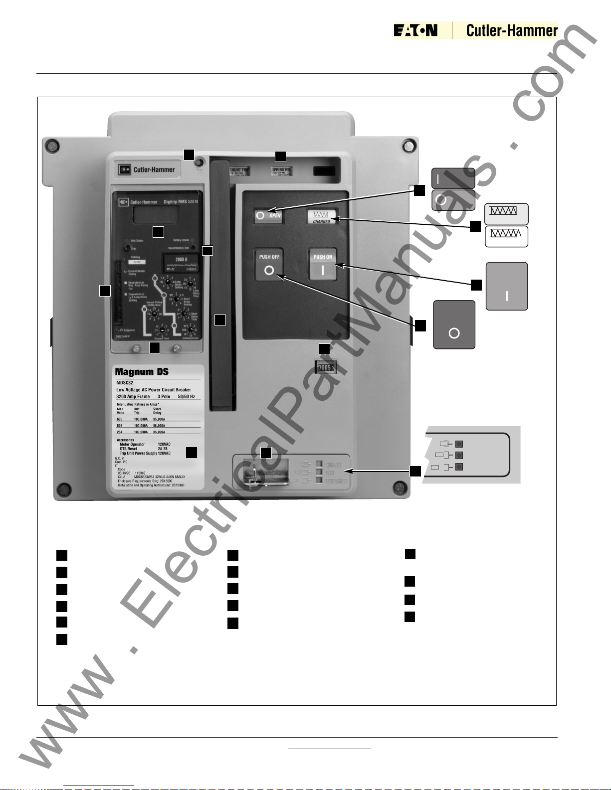
Figure 3-5 Typical Magnum DS/DSX Drawout Circuit Breaker Front Cover
Trip Flag (Pop Out Indicator)
Three Accessory Windows
Trip Unit
Rating Plug
Contact Status (Open-Close)
Spring Status (Charged-Discharged)
2
1
4
3
6
2
1
8
7
10
3
9
11
12
Manual “OFF” Button (Push)
Manual “ON” Button (Push)
Manual Charge Handle
Optional Operation Counter
Padlockable Levering Device Access
Door for Drawout Breaker
5
8
7
Color Coded-Breaker
Position Indicator
Nameplate
Trip Unit Test Port
Trip Unit Cover with Two
Mounting Screws (Mounting
Screws will Accept Customer
Supplied Lead Security Meter
Seals
10
9
11
(Red)
(Green)
(Yellow)
(White)
(Green)
(Red)
5
13
14
12
13
4
14
15
6
15
Red = Connect
Yellow = Test
Green = Disconnect
www . ElectricalPartManuals . com
CLOSED
OPEN
CHARGED
DISCHARGED
PUSH ON
PUSH OFF
CONNECT
CONNECT
TEST
TEST
DISCONNECT
DISCONNECT
3-2 BASIC CIRCUIT BREAKER ASSEMBLY
All Magnum circuit breakers use a rigid frame housing
construction of engineered thermoset composite resins.
This construction provides high strength structural properties, excellent dielectric characteristics and resistance
to arc tracking.
The 3-piece construction approach provides support
while isolating and insulating power conductors (Figure
3-6):
(1) A 2-piece engineered thermoset composite resin
case encloses current paths and arc chambers. The
chambers act to channel arc gases up and out of the circuit breaker during interruption.
(2) The operating mechanism sits on the front of the
case and is electrically isolated and insulated from current contact structures. It is covered by an insulating
front cover.
3-3 POLE UNITS
A current carrying pole unit is individually enclosed and
rigidly supported by the case. The individual chambers
provide for pole unit isolation and insulation from one
another. Each pole unit has one primary contact
assembly, which consists of a moving portion and a
fixed portion. The exact design configuration depends
upon the breaker’s frame size. Circuit breakers with
frame sizes of 4000 amperes and higher use two pole
units and arc chute assemblies connected mechanically
and electrically in parallel to form one phase.
I.B. 2C12060H08
For more information visit: www.EatonElectrical.com
Instruction Book
Page 15
Effective: May 2006
Figure 3-6 Typical Magnum Construction (Right Side
View)
2
1
3-1.1 MDSL APPLICATION/OPERATION
MDSL circuit breakers are intended for applications
requiring the overload protection and switching functions
of air circuit breakers on systems whose available fault
currents (1) exceed the interrupting ratings of the circuit
breakers alone and/or (2) exceed the withstand and
interrupting ratings of downstream circuit components.
The 800 through 2000 amp frame MDSL circuit breakers have integrally mounted limiters on the drawout
breaker element. On overloads and faults within the circuit breaker interrupting rating, the circuit breaker protects the limiters. On higher fault currents exceeding
the circuit breaker rating, the limiters protect the circuit
breaker.
Interlock arrangements trip the circuit breaker whenever
any limiter blows. The circuit breaker cannot be
reclosed on a live source unless there are three
unblown limiters on the circuit. The blown fuse indicator, located on the front of the circuit breaker, provides a
visual indication when a current limiter in any phase has
interrupted a short circuit. In addition, a blown limiter
sensing circuit insures that a circuit breaker will be
tripped when any current limiter has blown, preventing
single phasing.
The MDSL circuit breaker must be completely withdrawn from its compartment onto the compartment’s
extension rails, thus assuring complete isolation, before
the integral current limiters are accessible.
Additional information concerning current limiter ratings,
limiter replacement and blown fuse operation is provided later in this chapter.
2
1
Figure 3-7 Features of Magnum Moving Conductor
Assembly
Pivot
Point
Single Contact
Finger
Moving
Arcing
Contact
Area
(Toe)
Moving Main Contact
Conductive Pad
(Heel)
Dual
Flexible
Connections
(Case)(Front Cover)
www . ElectricalPartManuals . com
I.B. 2C12060H08
For more information visit: www.EatonElectrical.com
Instruction Book
Page 16
Effective: May 2006
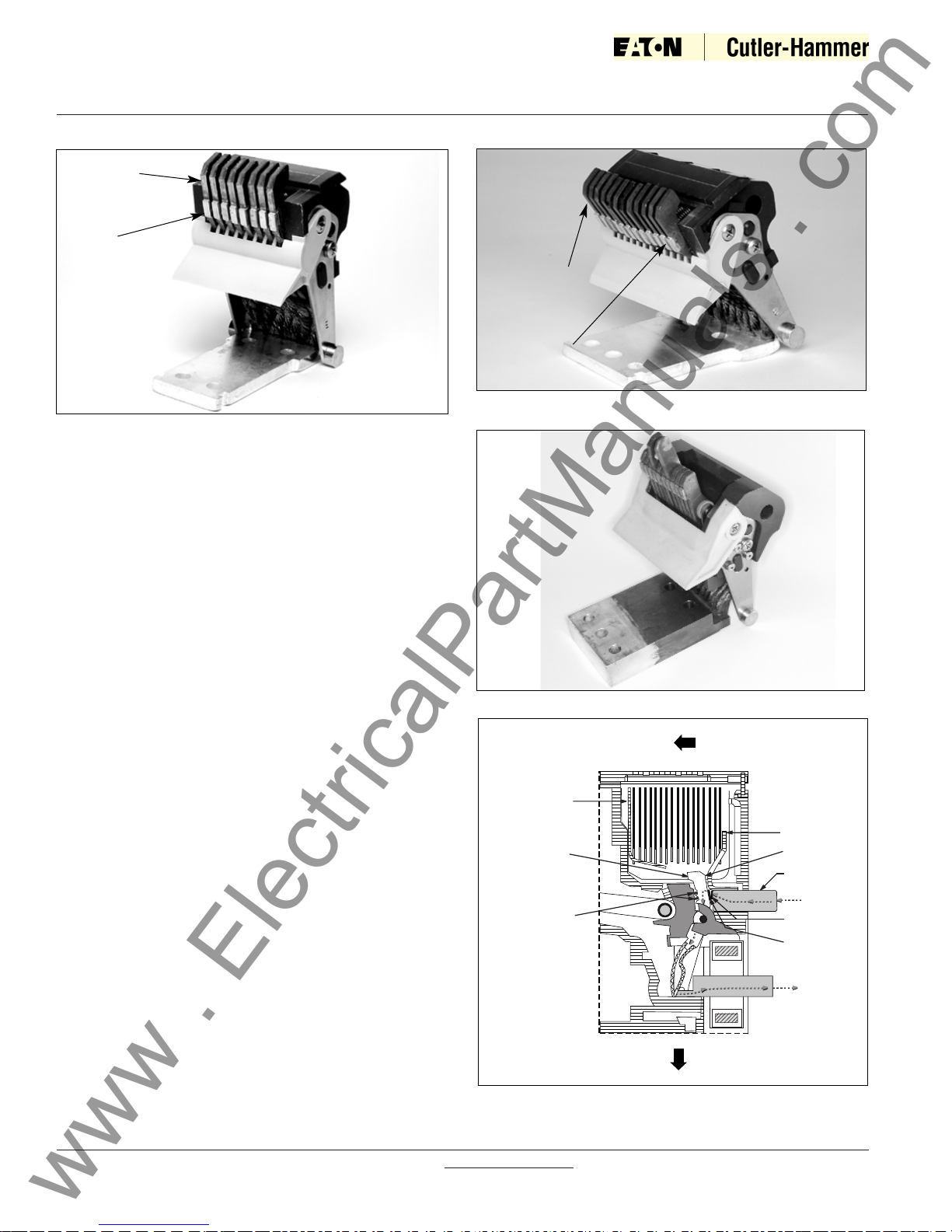
Figure 3-9 Standard Frame DS (12-finger) Moving
Conductor Assembly
Figure 3-10 General Partial Cross-Sectional View (Shown
in Closed Position) (not specific to any family/frame)
3-3.1 PRIMARY MOVING CONTACTS
Depending upon the frame size, each primary moving
contact assembly is comprised of multiple individual
copper contact fingers connected to the load conductor
through flexible braided connectors (Figure 3-8). Two
flexible connectors are used to connect each finger to
the load conductor. The number of fingers used
depends upon the circuit breaker’s continuous and
short-circuit current ratings (Figures 3-8 and 3-9). On
some ratings fingers are removed and replaced with
spacers.
The single contact finger performs both the main and
arcing contact functions on different parts of the same
finger (Figure 3-7). A highly conductive alloy pad is part
of the contact finger and functions as the moving main
contact, and is called the “Heel.” The tip of the same
contact finger functions as the moving arcing contact,
and is called the “Toe.”
In addition to the contact finger information given above,
DSX (MDSX) utililize an inner and outer carriage design
to facilitate a fast opening blow open contact structure
(Figure 3-9a). The contact fingers mounted in the inner
contact carrier can move independently from both the
outer carrier and the opening mechanism in the breaker.
This independence is the core design feature of its fast
opening blow open contact structure.
Figure 3-8 Narrow Frame (8-finger) Moving Conductor
Assembly
“Heel”
(Main Contact)
“Toe”
(Arcing Contact)
“Toe”
(Arcing Contact)
“Heel”
(Main Contact)
Figure 3-9a MDSX Moving Contact Assembly
www . ElectricalPartManuals . com
Breaker
Front
Arc Chute
Integral
Moving Contact
Fingers
Moving Contact
Springs
Breaker
Bottom
xxxxxxxx
x
x
xxxxxxxx
xxxxxxxx
x
x
xxxxxxxx
x
x
x
x
Arc Runner
Arcing
Contact (Toe)
Line
Conductor
Current
Flow
Stationary
Main Contact
Moving Main
Contact (Heel)
Current
Flow
I.B. 2C12060H08
For more information visit: www.EatonElectrical.com
Instruction Book
Page 17
Effective: May 2006
complete the manual charging process. It is possible to
manually recharge the spring immediately after closing
the circuit breaker and before it has been tripped open.
Standard manually operated circuit breakers are closed
and opened by hand using the Manual “ON” and Manual
“OFF” buttons respectively located on the front of the circuit breaker (Figure 3-5). Performing either operation is
accomplished by pressing and releasing the appropriate
button. Access to these pushbuttons can be limited by
the use of an optional, padlockable cover. In addition,
complete access to the “ON” button can be prevented
with an optional prevent close cover. The status of the
springs and the primary contacts are always indicated in
an indicator window just above the pushbuttons.
Electrically operated optional devices are available to
automatically close or trip a manually operated circuit
breaker. An electrical spring release is available to close
a manually operated circuit breaker. Two optional
devices, a shunt trip and an undervoltage release, are
available to automatically trip (open) a manually operated
circuit breaker. All of these UL listed optional devices can
be installed easily in the field. For more details on these
devices, refer to paragraph 3-8 in this manual.
An electrical operator which is used to charge the closing
spring automatically can be added to a manually operated circuit breaker in the field (Figure 3-13). Manually
operated circuit breakers are pre-wired to accept this
addition.
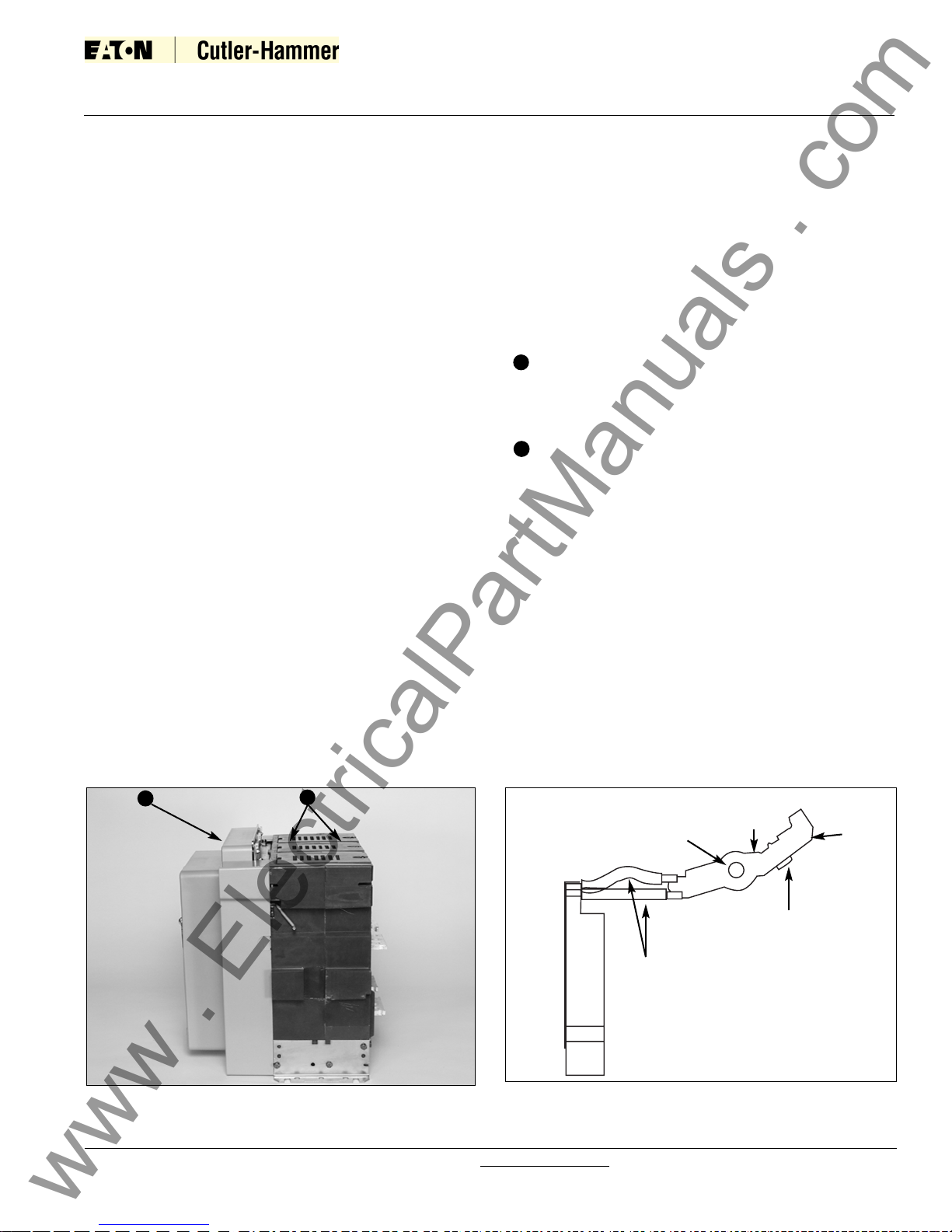
3-3.2 PRIMARY STATIONARY CONTACTS
The primary stationary contact is a combination of two
items (Figure 3-10). One is a conductive pad mounted
on the line conductor which functions as the stationary
main contact. The other is an arc runner, also connected to the line conductor. The integral arc runner serves
a dual purpose:
• Fixed arcing contact
• Part of the arc chute
3-4 OPERATING MECHANISM
The Magnum DS/DSX/DSL operating mechanism is
based on the proven cam and spring design of the DSII
power circuit breaker. It is easily accessed by removing
four cover screws and the front cover (Figure 3-11).
The mechanism is a two-step stored energy mechanism. Potential energy is stored to close the circuit
breaker. Sufficient energy to open the circuit breaker
remains available after a closing operation.
3-4.1 MANUAL OPERATION
On manually operated circuit breakers, the closing spring
can only be charged manually. To manually charge the
spring, insert one finger in the recess behind the charging
handle and pull out. This permits a gloved hand to grasp
the handle and begin charging (Figure 3-12). It takes
from 5 to 7 downward strokes on the charging handle to
Figure 3-11 Typical Electrically Operated Drawout MDS/MDSX Circuit Breaker with Front Cover Removed
Secondary Wiring Points
Field Installable Accessories
(3 maximum)
Trip Unit
Electric Charging Motor
Manual Charge Handle
Operations Counter (optional)
Padlockable Levering Device
Access Door
Breaker Position Indicator
7
2
1
4
3
5
6
8
2
1
3
5
6
7
8
4
www . ElectricalPartManuals . com
 Loading...