

Eaton Matrix 2000 Installation And Operation Manual

Matrix 2000 Inverter
Installation and Operation Guide
Issue:
IPN 997-00012-72C
Issue Date:
July 2017
Eaton Corporation
Telecommunications Power Solutions
www.eaton.com/telecompower
DCinfo@eaton.com

The product discussed in this literature is subject to terms and conditions outlined in Eaton selling policies. The
sole source governing the rights and remedies of any purchaser of this equipment is the relevant Eaton selling
policy.
No warranties, express or implied, including warranties of fitness for a particular purpose or merchantability, or
warranties arising from course of dealing or usage of trade, are made regarding the information,
recommendations and descriptions contained herein.
In no event will Eaton be responsible to the purchaser or user in contract, in tort (including negligence), strict
liability or otherwise for any special, indirect, incidental or consequential damage or loss whatsoever, including but
not limited to damage or loss of use of equipment, plant or power system, cost of capital, loss of power, additional
expenses in the use of existing power facilities, or claims against the purchaser or user by its customers resulting
from the use of the information, recommendations and descriptions contained herein.
The information contained in this literature is subject to change without notice.
Subject to the right to use its equipment, Eaton Corporation does not convey any right, title or interest in its
intellectual property, including, without limitation, its patents, copyrights and know-how.
No part of this document may be reproduced or transmitted in any form, by any means or for any purpose other
than the Purchaser’s personal use, without the express written permission of Eaton Corporation.
Eaton®, Matrix, Powerware®, IntergyTM, CellSureTM, SiteSureTM, PowerManagerIITM and DCToolsTM are trade
names, trademarks, and/or service marks of Eaton Corporation or its subsidiaries and affiliates. Unless otherwise
noted, brands, product names, trademarks or registered trademarks are the property of their respective holders.
Copyright © 2009-2010 Eaton Corporation. All Rights Reserved.

About This Guide
Copyright © 2017 Eaton Corporation. All Rights Reserved.
IPN 997-00012-72C July 2017
i
About This Guide
Purpose
The purpose of this manual is to provide explanations and procedures for installing, operating,
maintaining, and troubleshooting a Matrix 2000 Inverter.
This manual should be read through carefully before installation and operation.
Please retain this manual for future reference.
Audience
This guide is intended for use by:
Installers competent in:
installing and commissioning dc power systems and inverter systems
safe working practices for ac and dc powered equipment
the relevant local electrical safety regulations and wiring standards
Operators and maintenance staff competent in:
operation of dc power systems and inverter systems
safe working practices for ac and dc powered equipment
Reporting Problems with this Guide
Please use this email address to report any problems you find in this guide:
Eaton DC Product Marketing Communications
EMAIL: DCInfo@eaton.com
For Further Information and Technical Assistance
For further information and technical assistance see Worldwide Support on page 29.

Matrix Standalone Inverter
ii
Copyright © 2017 Eaton Corporation. All Rights Reserved.
IPN 997-00012-72C July 2017

Table of Contents
Copyright © 2017 Eaton Corporation. All Rights Reserved.
IPN 997-00012-72C July 2017
iii
Table of Contents
About This Guide
Purpose .............................................................................................................................................. i
Audience ........................................................................................................................................... i
Reporting Problems with this Guide .......................................................................................... i
For Further Information and Technical Assistance ................................................................. i
General Description
Overview .......................................................................................................................................... 1
Part Numbers .................................................................................................................................. 1
Front View ....................................................................................................................................... 2
Rear Views ....................................................................................................................................... 2
Preparation
Overview .......................................................................................................................................... 3
General ............................................................................................................................................. 3
Battery Precautions ........................................................................................................................ 4
Inspecting the Equipment and Reporting Damage ................................................................ 4
Installation
Overview .......................................................................................................................................... 5
Location ............................................................................................................................................ 5
Unpacking and Inspection ........................................................................................................... 5
Mounting ......................................................................................................................................... 6
AC Connections .............................................................................................................................. 6
DC Connections .............................................................................................................................. 6
Remote Control and Alarm Connections (Optional) ............................................................. 7
Remote Control ................................................................................................................................ 7
Alarm Connections ......................................................................................................................... 8
Operation
Overview .......................................................................................................................................... 9
Pre-Operation Check ..................................................................................................................... 9
Inverter Standalone check list ........................................................................................................ 9
Apply Power ................................................................................................................................. 10
Remote Control Operation (Optional) ........................................................................................ 10
Main Menu .................................................................................................................................... 10
Status Menu ................................................................................................................................... 11
Settings Menu ............................................................................................................................... 12
Inverter Parameter Settings ......................................................................................................... 12
System Parameter Settings ........................................................................................................... 13
Maintenance
Overview ........................................................................................................................................ 15
Troubleshooting ........................................................................................................................... 16
LED display status (Low to High Priority)............................................................................. 17
Alarm Codes ................................................................................................................................. 18

Matrix Standalone Inverter
iv
Copyright © 2017 Eaton Corporation. All Rights Reserved.
IPN 997-00012-72C July 2017
Appendix A Specifications
Appendix B Default Values
Appendix C Menu
Equipment Incident Report
Worldwide Support
Index
Chapter 1
General Description
Copyright © 2017 Eaton Corporation. All Rights Reserved.
IPN 997-00012-72C July 2017
1
C h a p t e r 1
General Description
Overview
Topic Page
Part Numbers 1
Front View 2
Rear Views 2
The Matrix Standalone Inverter is a 1U, 19-inch rack mount module with output up to
2000VA/2000W (at 110/115/120 or 208/220/230/240V ac, 50 or 60Hz) from -48V dc input.
The module has a built-in automatic transfer switch (ATS), high efficiency and a wide operating
temperature range.
Alarm and monitoring is provided by an LCD screen, alarm LEDs and an alarm relay output.
Part Numbers
Part Number
Description
INV-4820ESA
Matrix 2000, 2000VA/2000W standalone inverter module with
automatic transfer switch, 230V ac nominal output. 2 x IEC 320-C13
output sockets.
INV-4820SA
Matrix 2000, 2000VA/2000W standalone inverter module with
automatic transfer switch, 120V ac nominal output. 2 x NEMA 5-20R
output sockets. Includes AC input cord.
For full details refer to the Specifications on page 19.
Matrix Standalone Inverter
2
Copyright © 2017 Eaton Corporation. All Rights Reserved.
IPN 997-00012-72C July 2017
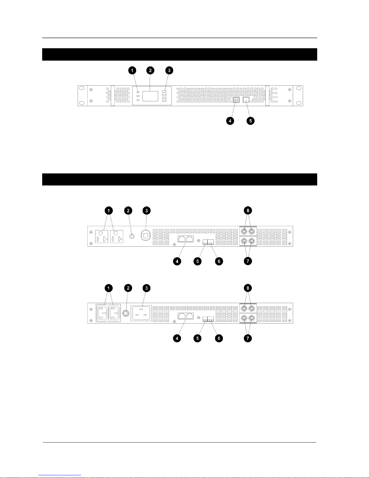
Front View
LEDs: Power (green), minor alarm (yellow), major
alarm (red). See Troubleshooting on page 16.
LCD screen. See Menu details on page 10.
Keypad
USB 1.1 connector (reserved for future use)
ON/OFF power switch
Rear Views
120V Model
230V Model
AC output connectors (see Specifications on page
20).
AC input circuit breaker. Push in to reset.
120V models: AC input cord, 230V models: AC
input connector (see Specifications on page 19).
Parallel signal port (reserved for future use).
Remote on/off connector/screw terminals (wire
size: 0.5 - 2.0mm2, 20 - 14 AWG). See details on
page 7.
Alarm relay output connector/screw terminals (wire
size: 0.5 - 2.0mm2, 20 - 14 AWG). See details on
page 7.
48V dc negative (-) input terminals. 1/4" studs, 5/8"
separation.
48V dc positive (+) input terminals. 1/4" studs, 5/8"
separation.
Chapter 2
Preparation
Copyright © 2017 Eaton Corporation. All Rights Reserved.
IPN 997-00012-72C July 2017
3
C h a p t e r 2
Preparation
Overview
Topic Page
General 3
Battery Precautions 4
Inspecting the Equipment and Reporting Damage 4
General
1 Only mount the Matrix 2000 Inverter in either an open-frame relay rack or an enclosed
cabinet. The Matrix 2000 Inverter is not designed for "bench top" or any other mounting
arrangement.
2 Before installing and using the Matrix 2000 Inverter, read all instructions and cautionary
markings on the equipment and all appropriate sections of this guide. Be sure to read all
instructions and cautionary markings for any equipment attached to this unit.
3 This unit is designed for indoor use only. Do not expose the equipment to rain, snow, or
spray.
4 To reduce the risk of fire hazard, do not cover or obstruct the ventilation openings. Do not
install the equipment in a zero-clearance compartment.
5 Use only attachments recommended or sold by the manufacturer. Doing otherwise may
result in a risk of fire, electric shock, or other injury.
6 To avoid a risk of fire and electric shock, make sure that existing wiring is in good
condition and is not undersized. Do not operate the equipment with damaged or
substandard wiring.
7 Do not operate the equipment if it has been damaged in any way.
8 The Earthing System of the AC output from the inverter will change depending on
whether it is in Mains Priority or Battery Priority (DC supply) mode. When in Mains
Priority the AC output earthing system is the same as the AC supply network. When in
Battery Priority the AC output earthing system is floating and the Neutral system
arrangement at the Inverter output becomes “insulated” (IT), meaning both L1 and L2
being isolated from earth. This is the consequence of a requirement to isolate the input
AC terminals when operating in Battery priority as the AC input is made via a pluggable
connector. Due to EMC capacitors between L1 and L2 and earth, it is possible to measure
half the nominal output voltage between L1 or L2 and earth. This is expected and only
presents a low energy source.
9 Due to the earthing system outlined above, local electricity regulations of certain
countries may mandate the fitment of an Insulation Monitoring Device (IMD) on the
output, and/or the fitment of equipotential bonding conductors between all
simultaneously accessible exposed conductive parts of fixed equipment and extraneous
conductive parts Check with your local regulations.
10 It is not permitted to bond L1 or L2 to earth on the output.

Matrix Standalone Inverter
4
Copyright © 2017 Eaton Corporation. All Rights Reserved.
IPN 997-00012-72C July 2017
Battery Precautions
To avoid personal injury and property damage, read these battery precautions on handling,
charging and disposing of batteries.
1 Never reverse the INPUT+ and INPUT- polarity to the battery.
2 Keep the battery away from heat sources including direct sunlight, open fires, microwave
ovens, and high-voltages. Temperatures over 60ºC may cause damage. Make sure the area
around the battery is well ventilated.
3 Never smoke or allow a spark or flame near the battery.
4 Use caution to reduce the risk of dropping a metal tool on the battery. A spark or short
circuit to the battery or other electrical parts could cause an explosion.
5 Remove all metal items, such as rings, bracelets, and watches when working on the
batteries.
6 Have plenty of fresh water and soap nearby in case battery acid contacts skin, clothing, or
eyes.
7 If battery acid contacts skin or clothing, wash immediately with soap and water. If acid
enters your eye, immediately flood it with running cold water for at least twenty minutes
and get medical attention immediately.
8 If you need to remove a battery, always remove the grounded terminal from the battery
first. Make sure all accessories are off so you do not cause a spark.
Inspecting the Equipment and Reporting Damage
Unpack the equipment and inspect it carefully for possible damage that may have occurred
while in transit. Do not use any damaged equipment.
Report any damage immediately, using a completed Equipment Incident Report on page 27.
Keep the original packaging to use if any item needs to be returned for replacement or repair.

Chapter 3
Installation
Copyright © 2017 Eaton Corporation. All Rights Reserved.
IPN 997-00012-72C July 2017
5
C h a p t e r 3
Installation
Overview
Topic Page
Location 5
Unpacking and Inspection 5
Mounting 6
AC Connections 6
DC Connections 6
Remote Control and Alarm Connections (Optional) 7
Location
Install the Matrix 2000 in a location that meets the following requirements:
Dry: Do not allow water to drip or splash on the inverter.
Cool: Ambient air temperature between -20°C and 50°C.
If the Matrix 2000 is installed in a closed or multi-unit rack assembly, the operating ambient
temperature of the rack environment may be greater than room ambient.
Safe: Do not install in a battery compartment or other areas where flammable fumes may
exist, such as fuel storage areas or engine compartments.
Ventilated: Allow at least 75mm (3") clearance all around for air flow. Ensure the
ventilation openings on the front, rear and top of the unit are not obstructed.
If the Matrix 2000 is installed in a closed rack, ensure there is adequate air flow.
Corrosion and Dust Free: Do not install in a corrosive or dusty environment where
contaminants (such as salt), dust, wood particles or other filings/shavings are present that
may be pulled into the unit when the cooling fan is operating.
Close to Batteries: Avoid excessive cable lengths but do not install in the same
compartment as batteries. Use the recommended wire lengths and sizes (see details on
page 6).
Avoid mounting the inverter where it may be exposed to the gases produced by the battery.
Prolonged exposure to these corrosive gases will damage the inverter.
Unpacking and Inspection
Remove the unit from its packaging and inspect it for scratches, cracks, broken connectors and
missing accessories. Refer to Inspecting the Equipment and Reporting Damage on page 4.

Matrix Standalone Inverter
6
Copyright © 2017 Eaton Corporation. All Rights Reserved.
IPN 997-00012-72C July 2017
The Matrix 2000 includes the following accessories:
4 x M4 screws to connect the brackets to the rack
2 x 19-inch rack mount brackets (factory-fitted)
2 x 23-inch rack mount brackets
Mounting
1 If the Matrix 2000 is to be mounted in a 23-inch rack:
Remove the factory-fitted 19-inch rack mount brackets.
Attach the 23-inch rack mount brackets.
2 Mount the Matrix 2000 in the rack:
Fit cage nuts in the rack.
Position the Matrix 2000.
Align the holes of mounting brackets and rack.
Secure with four cross screws provided.
AC Connections
The ground wire of the ac input must be connected to the ground from your ac utility
source.
The ground wire of the ac output must be connected to the grounding point for your loads.
Do not operate the unit without connecting it to ground. Electrical shock hazard may
result.
1 Refer to the Specifications on page 19 for the correct ac input and output plugs/sockets.
120V models are supplied with an ac input cord and plug.
2 Either:
For 230V models, connect an ac cord from the ac input plug to a nearby (easily
accessible) ac outlet.
or:
For 120V models, connect the ac cord to a nearby (easily accessible) ac outlet.
3 Connect ac cords from the ac output plugs to the load equipment.
DC Connections
The maximum dc input current is 46.3A. The cables from the dc supply to the Matrix 2000 must
be in accordance with local electrical codes or regulations.
Recommended input circuit protection: 60A.
Recommended cable size: 6AWG/10mm
2
(copper).
Increase the cable size if the dc supply is more than 10 feet/3m from the Matrix 2000.
Maximum cable size is 2AWG/25mm2.
Cables that are too small or too long will cause decreased inverter performance such as poor surge
capability and frequent low input voltage warnings and shutdowns. These low input voltage
warnings are due to dc voltage drop across the cables from the inverter to the dc supply. The
longer and/or smaller these cables, the greater the voltage drop.
 Loading...