

Eaton Magnum SB Series, Magnum DS Series, Magnum IEC Series Technical Product Manual
Magnum DS, SB and IEC low voltage power circuit breakers
Courtesy of NationalSwitchgear.com
Technical product guide
Table of content
Courtesy of NationalSwitchgear.com
1 Overview of the Magnum low voltage circuit breaker
Magnum DS family ...................................................4
Magnum SB family ...................................................6
Magnum IEC family ..................................................7
Magnum DC switch family .............................................8
2 Family features and characteristics
Universal family features ...............................................9
High performance interruption & withstand levels ...........................9
Continuous current ratings .............................................9
Sizes, dimensions, weights and configurations .............................9
Design configuration flexibility .........................................11
User friendly front cover ..............................................12
Front cover details features ...........................................13
Construction characteristics ...........................................14
Rigid frame housing .................................................14
Three piece construction .............................................14
Two-step stored energy mechanism .....................................14
Unsurpassed performance design ......................................14
Value added features ................................................14
Breaker mounting configurations .......................................14
Drawout mounting ..................................................15
Cassettes – Available styles ...........................................15
Renewal parts for extended life and longevity .............................16
3 Magnum DS - Product specic information
Standards and certifications ...........................................17
Selection and identification of ratings for Magnum DS ......................17
Catalog number selection table ........................................18
Magnum DS - Continuous amperage, interruption and withstand ratings tables ...21
Magnum DS - Current limiting circuit breakers .............................23
4 Magnum SB - Product specic information
Standards and certifications ...........................................25
Selection and identification of ratings for Magnum SB ......................26
Catalog number selection table ........................................27
Magnum SB - Continuous amperage, interruption and withstand ratings tables ...30
1
1
1
1
1
1
1
1
1
1
1
1
1
1
1
1
1
1
1
1
1
1
1
5 Magnum IEC - Product specic information
Standards and certifications ...........................................32
Selection and identification of ratings for Magnum IEC ......................33
Catalog number selection table ........................................34
Magnum IEC - Continuous amperage, interruption and withstand ratings tables ..37
6 Magnum DC - Product specic information
Standards and certifications ...........................................39
Magnum DC switches selection ........................................40
PUBLICATION TITLE CA000000 00E—April 2017 www.eaton.com 2
1
1
1
1
1
1
1
Table of content
Courtesy of NationalSwitchgear.com
7 Magnum trip units and communication devices
Overview of Digitrip (TM) electronic trip units .............................41
Digitrip trip units – Features ...........................................43
Digitrip trip units – Comprehensive features. . . . . . . . . . . . . . . . . . . . . . . . . . . . . . . 46
Additional modules for Digitrip 1150 trip units .............................48
Other communication related devices ...................................50
Ground fault provisions and protective schemes ...........................51
8 Accessory devices and connections
Overview of Magnum accessories ......................................52
Plug-in electrical accessories ..........................................52
Internal electrical accessories ..........................................54
Mechanical accessories ..............................................55
9 Technical data and endurance information for installation
Technical data for usual service conditions (0°C to 40°C) .....................59
Quick reference for other documents and information - outlined drawings .......62
10 Applications and other miscellaneous engineering data
Applications for Magnum circuit breakers ................................63
11 Magnum drawings and outlines
Table of contents for Magnum drawings and outlines .......................64
Engineering document references chart ..................................66
1
1
1
1
1
1
1
1
1
1
1
1
1
1
1
1
1
1
1
1
1
1
1
1
1
1
1
1
1
1
PUBLICATION TITLE CA000000 00E—April 2017 www.eaton.com 3
Overview of the Magnum low voltage circuit breaker
Courtesy of NationalSwitchgear.com
1
1
1
1
1
1
1
1
1
1
1
1
1
1
1
1
1
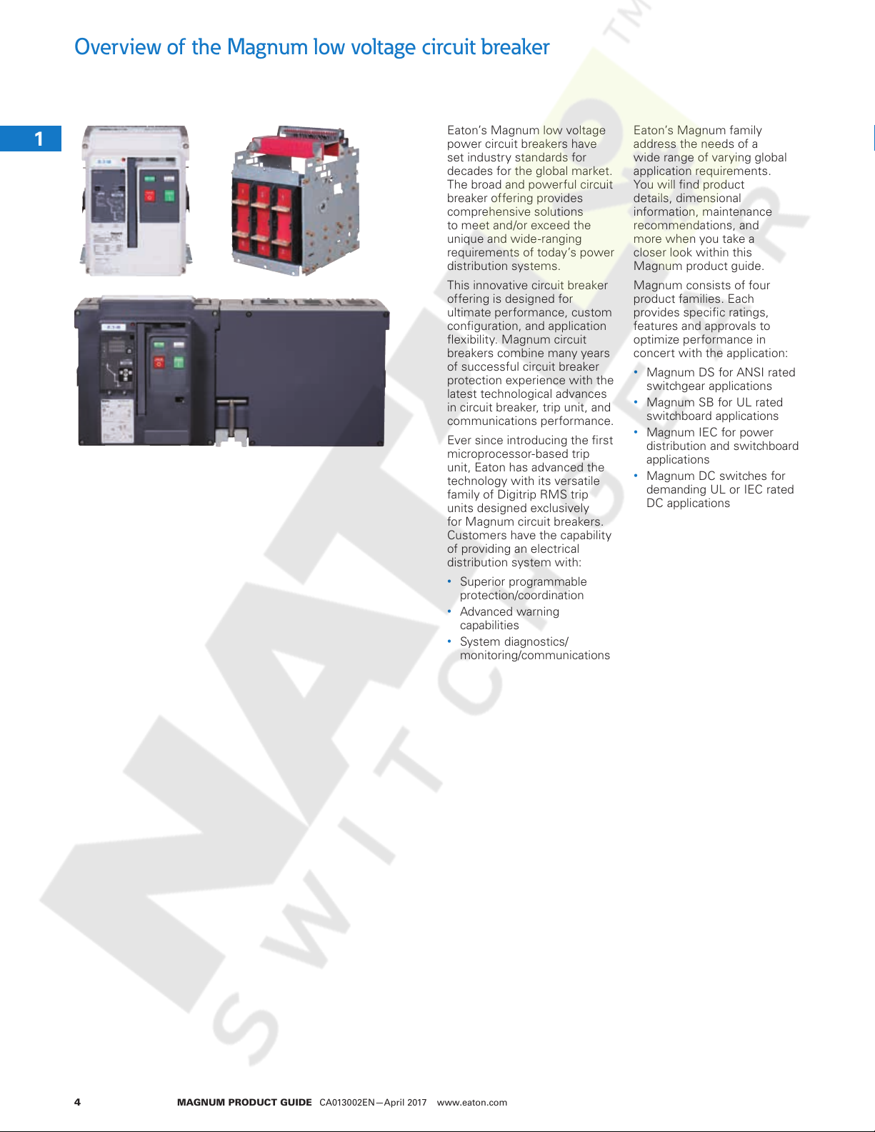
Eaton’s Magnum low voltage
power circuit breakers have
set industry standards for
decades for the global market.
The broad and powerful circuit
breaker offering provides
comprehensive solutions
to meet and/or exceed the
unique and wide-ranging
requirements of today’s power
distribution systems.
This innovative circuit breaker
offering is designed for
ultimate performance, custom
configuration, and application
flexibility. Magnum circuit
breakers combine many years
of successful circuit breaker
protection experience with the
latest technological advances
in circuit breaker, trip unit, and
communications performance.
Ever since introducing the first
microprocessor-based trip
unit, Eaton has advanced the
technology with its versatile
family of Digitrip RMS trip
units designed exclusively
for Magnum circuit breakers.
Customers have the capability
of providing an electrical
distribution system with:
•
Superior programmable
protection/coordination
•
Advanced warning
capabilities
•
System diagnostics/
monitoring/communications
Eaton’s Magnum family
address the needs of a
wide range of varying global
application requirements.
You will find product
details, dimensional
information, maintenance
recommendations, and
more when you take a
closer look within this
Magnum product guide.
Magnum consists of four
product families. Each
provides specific ratings,
features and approvals to
optimize performance in
concert with the application:
•
Magnum DS for ANSI rated
switchgear applications
•
Magnum SB for UL rated
switchboard applications
•
Magnum IEC for power
distribution and switchboard
applications
•
Magnum DC switches for
demanding UL or IEC rated
DC applications
1
1
1
1
1
1
1
1
1
1
1
1
1
MAGNUM PRODUCT GUIDE CA013002EN—April 2017 www.eaton.com4
Overview of the Magnum low voltage circuit breaker
Courtesy of NationalSwitchgear.com
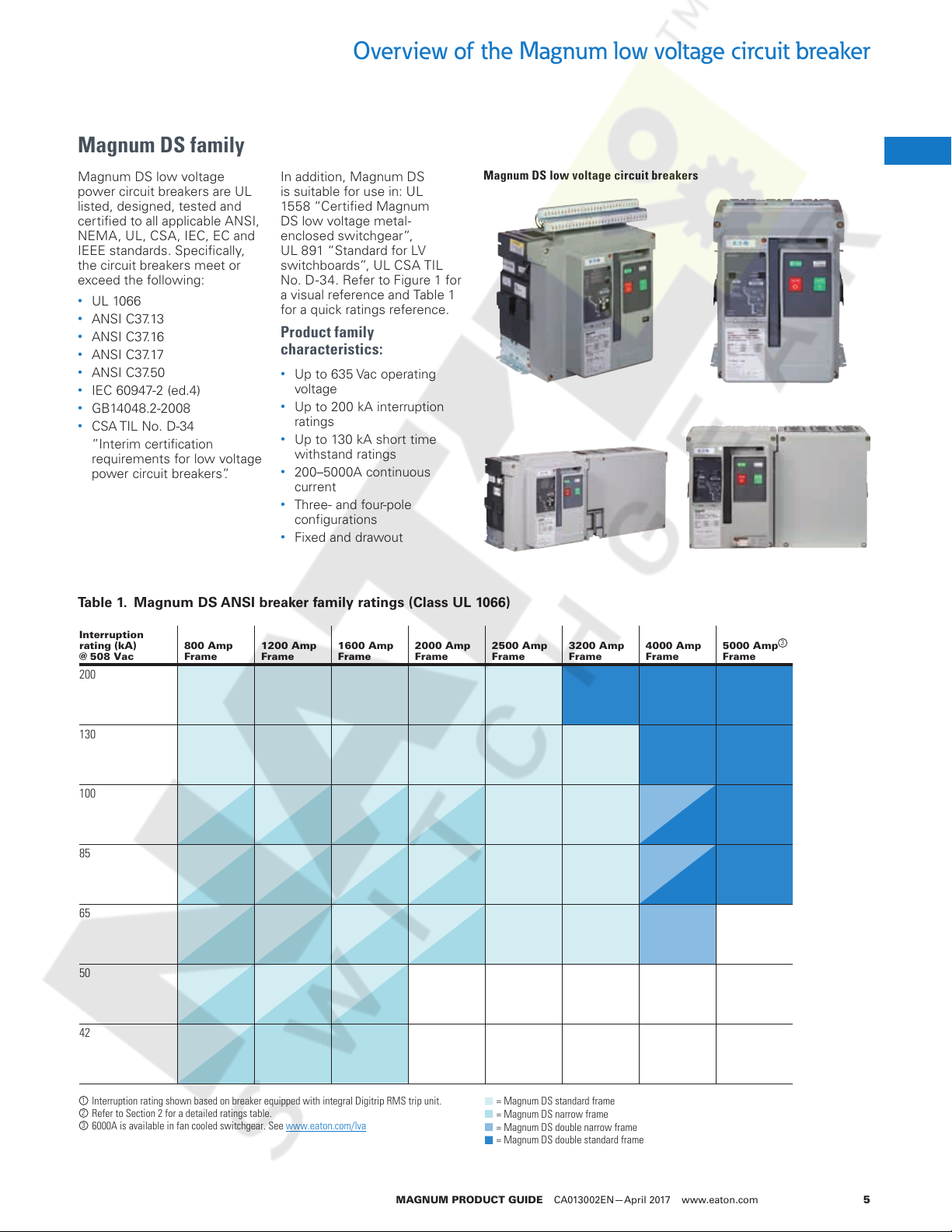
Magnum DS family
Magnum DS low voltage
power circuit breakers are UL
listed, designed, tested and
certified to all applicable ANSI,
NEMA, UL, CSA, IEC, EC and
IEEE standards. Specifically,
the circuit breakers meet or
exceed the following:
•
UL 1066
•
ANSI C37.13
•
ANSI C37.16
•
ANSI C37.17
•
ANSI C37.50
•
IEC 60947-2 (ed.4)
•
GB14048.2-2008
•
CSA TIL No. D-34
”Interim certification
requirements for low voltage
power circuit breakers”.
Table 1. Magnum DS ANSI breaker family ratings (Class UL 1066)
Interruption
rating (kA)
@ 508 Vac
200
800 Amp
Frame
In addition, Magnum DS
is suitable for use in: UL
1558 “Certified Magnum
DS low voltage metal-
enclosed switchgear”,
UL 891 “Standard for LV
switchboards”, UL CSA TIL
No. D-34. Refer to Figure 1 for
a visual reference and Table 1
for a quick ratings reference.
Product family
characteristics:
•
Up to 635 Vac operating
voltage
•
Up to 200 kA interruption
ratings
•
Up to 130 kA short time
withstand ratings
•
200–5000A continuous
current
•
Three- and four-pole
configurations
•
Fixed and drawout
1200 Amp
Frame
1600 Amp
Frame
2000 Amp
Frame
Magnum DS low voltage circuit breakers
2500 Amp
Frame
3200 Amp
Frame
4000 Amp
Frame
5000 Amp
Frame
1
1
1
1
1
1
1
1
1
1
1
1
1
1
1
3
1
1
130
100
85
65
50
42
1
Interruption rating shown based on breaker equipped with integral Digitrip RMS trip unit.
2
Refer to Section 2 for a detailed ratings table.
3
6000A is available in fan cooled switchgear. See www.eaton.com/lva
= Magnum DS standard frame
= Magnum DS narrow frame
= Magnum DS double narrow frame
= Magnum DS double standard frame
1
1
1
1
1
1
1
1
1
1
1
1
1
MAGNUM PRODUCT GUIDE CA013002EN—April 2017 www.eaton.com 5
Overview of the Magnum low voltage circuit breaker
Courtesy of NationalSwitchgear.com
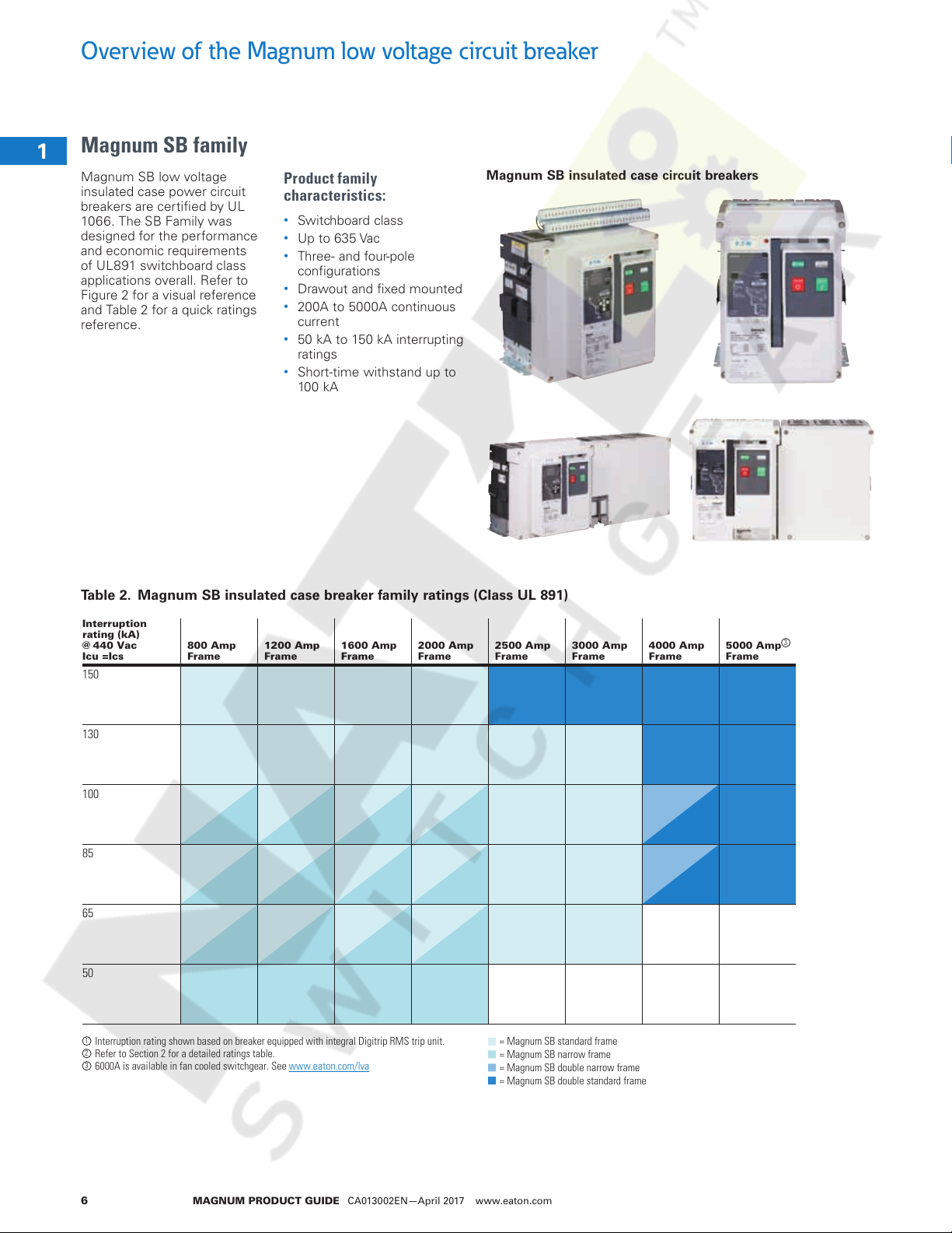
Magnum SB family
1
Magnum SB low voltage
1
insulated case power circuit
breakers are certified by UL
1066. The SB Family was
1
designed for the performance
and economic requirements
1
of UL891 switchboard class
applications overall. Refer to
1
Figure 2 for a visual reference
and Table 2 for a quick ratings
1
reference.
1
1
1
1
1
Product family
characteristics:
•
Switchboard class
•
Up to 635 Vac
•
Three- and four-pole
configurations
•
Drawout and fixed mounted
•
200A to 5000A continuous
current
•
50 kA to 150 kA interrupting
ratings
•
Short-time withstand up to
100 kA
Magnum SB insulated case circuit breakers
1
1
1
Table 2. Magnum SB insulated case breaker family ratings (Class UL 891)
Interruption
1
rating (kA)
@ 440 Vac
Icu =Ics
1
150
800 Amp
Frame
1200 Amp
Frame
1600 Amp
Frame
2000 Amp
Frame
1
1
130
1
100
1
1
85
1
1
65
1
1
50
1
2500 Amp
Frame
3000 Amp
Frame
4000 Amp
Frame
5000 Amp
Frame
3
1
1
1
Interruption rating shown based on breaker equipped with integral Digitrip RMS trip unit.
2
Refer to Section 2 for a detailed ratings table.
3
6000A is available in fan cooled switchgear. See www.eaton.com/lva
1
1
MAGNUM PRODUCT GUIDE CA013002EN—April 2017 www.eaton.com6
= Magnum SB standard frame
= Magnum SB narrow frame
= Magnum SB double narrow frame
= Magnum SB double standard frame
Overview of the Magnum low voltage circuit breaker
Courtesy of NationalSwitchgear.com
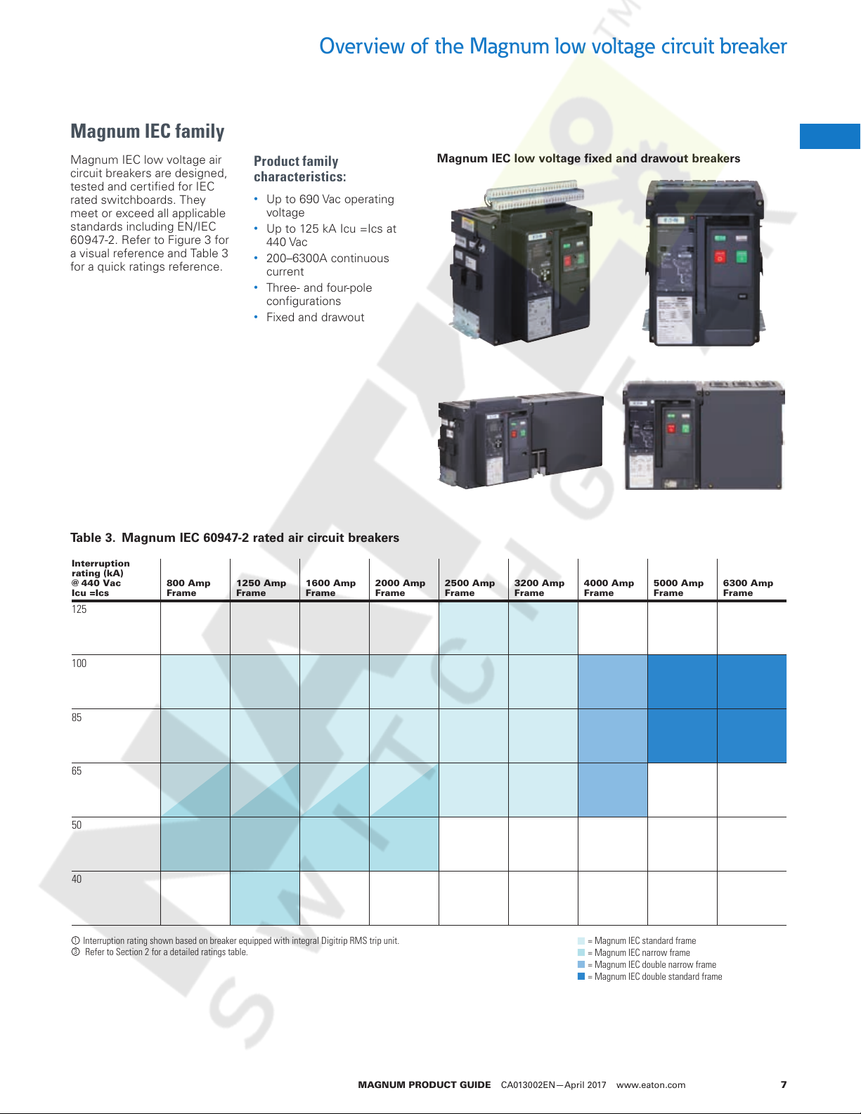
Magnum IEC family
Magnum IEC low voltage air
circuit breakers are designed,
tested and certified for IEC
rated switchboards. They
meet or exceed all applicable
standards including EN/IEC
60947-2. Refer to Figure 3 for
a visual reference and Table 3
for a quick ratings reference.
Table 3. Magnum IEC 60947-2 rated air circuit breakers
Product family
characteristics:
•
Up to 690 Vac operating
voltage
•
Up to 125 kA Icu =Ics at
440 Vac
•
200–6300A continuous
current
•
Three- and four-pole
configurations
•
Fixed and drawout
Magnum IEC low voltage fixed and drawout breakers
1
1
1
1
1
1
1
1
1
1
1
1
1
1
Interruption
rating (kA)
@ 440 Vac
Icu =Ics
125
100
85
65
50
40
1
Interruption rating shown based on breaker equipped with integral Digitrip RMS trip unit.
3
Refer to Section 2 for a detailed ratings table.
800 Amp
Frame
1250 Amp
Frame
1600 Amp
Frame
2000 Amp
Frame
2500 Amp
Frame
3200 Amp
Frame
4000 Amp
Frame
= Magnum IEC standard frame
= Magnum IEC narrow frame
= Magnum IEC double narrow frame
= Magnum IEC double standard frame
5000 Amp
Frame
6300 Amp
Frame
1
1
1
1
1
1
1
1
1
1
1
1
1
1
1
1
MAGNUM PRODUCT GUIDE CA013002EN—April 2017 www.eaton.com 7
Overview of the Magnum low voltage circuit breaker
(kA Interruption)
Courtesy of NationalSwitchgear.com
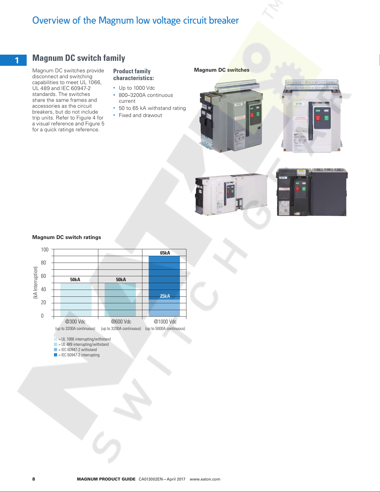
Magnum DC switch family
1
Magnum DC switches provide
1
disconnect and switching
capabilities to meet UL 1066,
UL 489 and IEC 60947-2
1
standards. The switches
share the same frames and
1
accessories as the circuit
breakers, but do not include
1
trip units. Refer to Figure 4 for
a visual reference and Figure 5
1
for a quick ratings reference.
1
1
1
1
1
Product family
characteristics:
•
Up to 1000 Vdc
•
800–3200A continuous
current
•
50 to 65 kA withstand rating
•
Fixed and drawout
Magnum DC switches
1
1
1
Magnum DC switch ratings
1
1
1
1
1
1
1
1
1
100
80
60
40
20
0
(up to 3200A continuous) (up to 3200A continuous) (up to 5000A continuous)
= UL 1066 interrupting/withstand
= UL 489 interrupting/withstand
= IEC 60947-2 withstand
= IEC 60947-2 interrupting
1
1
65kA
50kA 50kA
25kA
@300 Vdc @600 Vdc @1000 Vdc
1
1
1
1
1
MAGNUM PRODUCT GUIDE CA013002EN—April 2017 www.eaton.com8
Universal family features
Courtesy of NationalSwitchgear.com
As mentioned, Magnum low voltage power circuit breakers
consist of four product families. Although each family has
its own unique performance and features, each Magnum
breaker boasts a wide array of common design elements.
These common design elements deliver proven performance
with expanded capabilities, no matter which product family is
applied. To fulfill the latest market needs with proven reliability
and performance, Magnum is the clear choice for low voltage
applications.
High performance interruption &
withstand levels
Magnum provides Magnum provides large range withstand
and interrupting ratings to maximize selectivity and system
coordination.
•
A range from 42kA up to 200 kA interrupting - application on
power distribution systems with higher available fault currents.
•
Up to 130 kA withstand (short-time) - total selectivity/selective
coordination/discrimination between main, feeder, and branch
circuit breakers.
•
Current limiting performance - lower let-through currents for
superior equipment protection.
•
Optional Arc Flash Reduction Maintenance System
(ARMS™) - reduces arc flash hazards and improves operator
and maintenance safety.
•
Circuit breakers performance tested - meet or exceed all
applicable ANSI, NEMA, UL, CSA, IEC, EC and IEEE standards.
Specifically, the circuit breakers meet or exceed the following:
UL 1066, ANSI C37.13, ANSI C37.16, ANSI C37.17, ANSI C37.50,
IEC 60947-2, GB14048.2-2008, and CSA TIL No. D-34.
Family features and characteristics
•
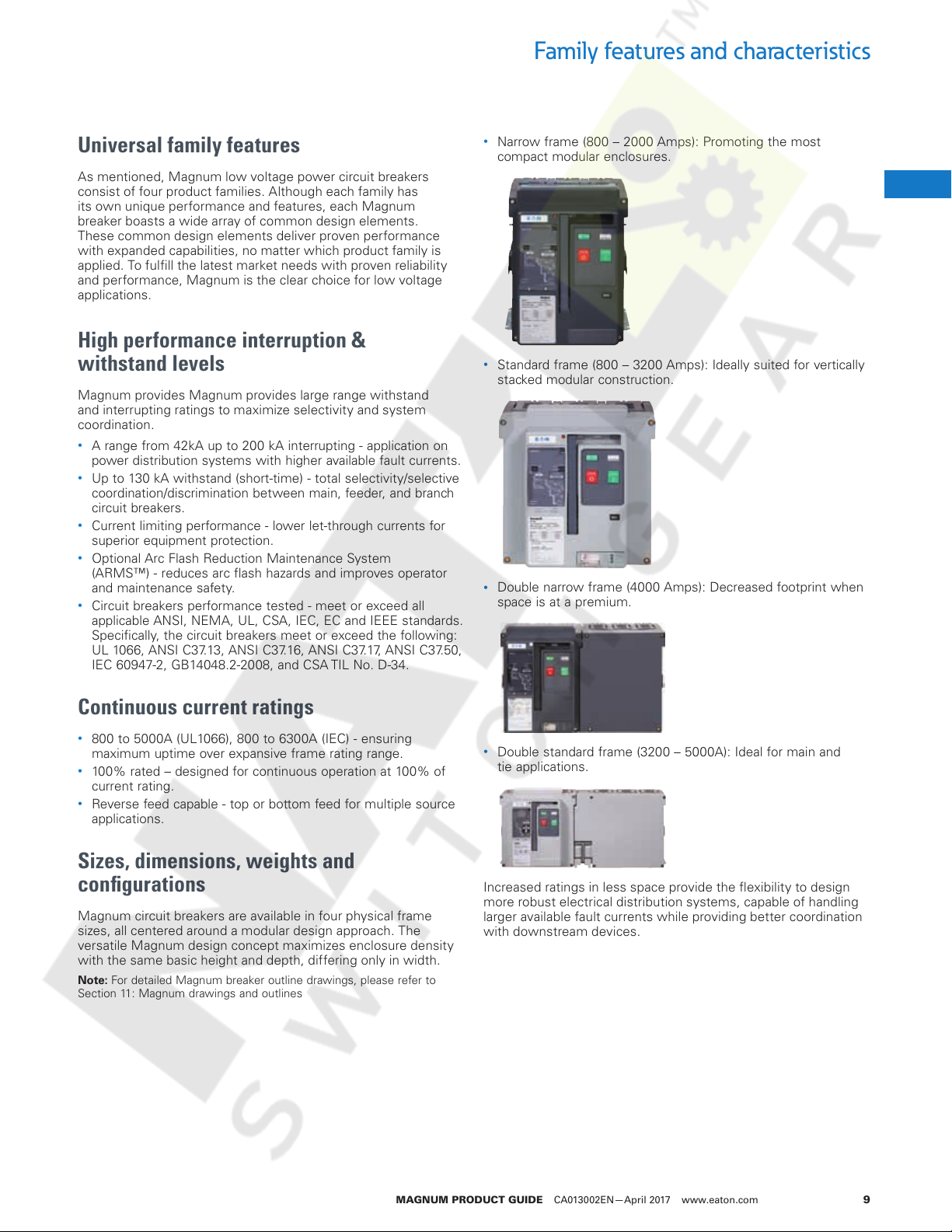
Narrow frame (800 – 2000 Amps): Promoting the most
compact modular enclosures.
•
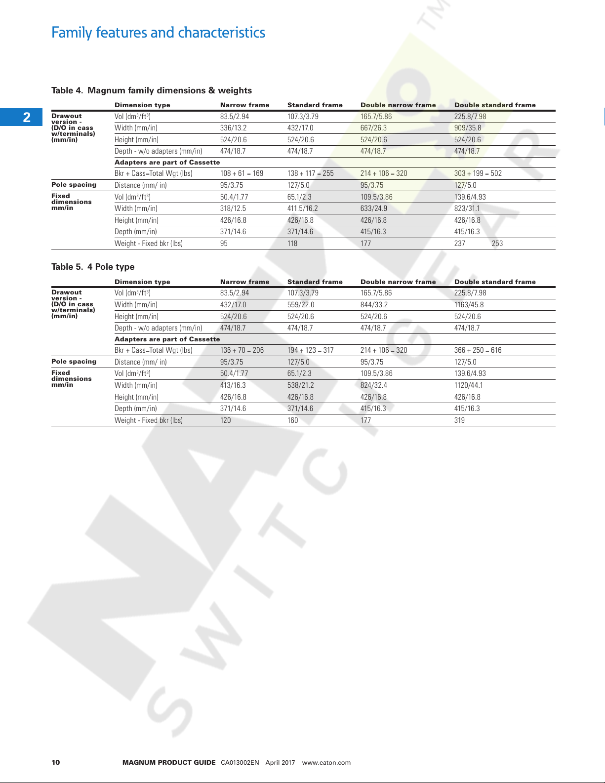
Standard frame (800 – 3200 Amps): Ideally suited for vertically
stacked modular construction.
•
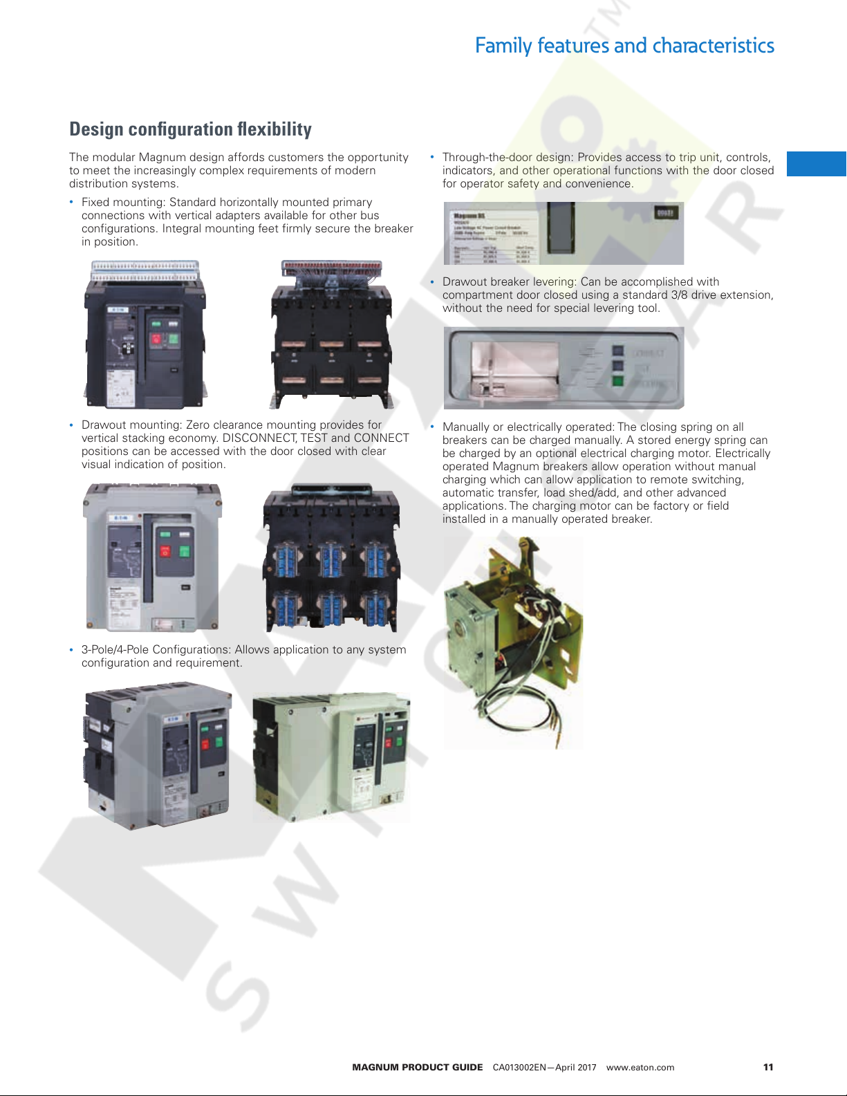
Double narrow frame (4000 Amps): Decreased footprint when
space is at a premium.
2
1
1
1
1
1
1
1
1
1
1
1
1
1
1
Continuous current ratings
•
800 to 5000A (UL1066), 800 to 6300A (IEC) - ensuring
maximum uptime over expansive frame rating range.
•
100% rated – designed for continuous operation at 100% of
current rating.
•
Reverse feed capable - top or bottom feed for multiple source
applications.
Sizes, dimensions, weights and
configurations
Magnum circuit breakers are available in four physical frame
sizes, all centered around a modular design approach. The
versatile Magnum design concept maximizes enclosure density
with the same basic height and depth, differing only in width.
ote:N For detailed Magnum breaker outline drawings, please refer to
Section 11: Magnum drawings and outlines
•
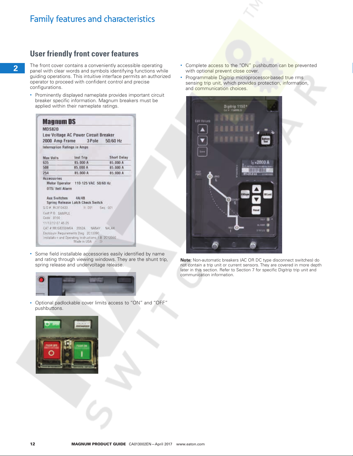
Double standard frame (3200 – 5000A): Ideal for main and
tie applications.
Increased ratings in less space provide the flexibility to design
more robust electrical distribution systems, capable of handling
larger available fault currents while providing better coordination
with downstream devices.
1
1
1
1
1
1
1
1
1
1
1
1
1
1
MAGNUM PRODUCT GUIDE CA013002EN—April 2017 www.eaton.com 9
Family features and characteristics
Courtesy of NationalSwitchgear.com
Table 4. Magnum family dimensions & weights
Dimension type Narrow frame Standard frame Double narrow frame Double standard frame
Drawout
2
version -
(D/O in cass
w/terminals)
(mm/in)
1
1
1
Pole spacing
Fixed
dimensions
1
mm/in
1
1
Table 5. 4 Pole type
1
1
Drawout
version -
(D/O in cass
w/terminals)
1
(mm/in)
1
1
Pole spacing
Fixed
1
dimensions
mm/in
1
1
Vol (dm3/ft3) 83.5/2.94 107.3/ 3.79 165.7/5.86 225.8/7.98
Width (mm/in) 33 6/13.2 432 /17. 0 667/26.3 909/35.8
Height (mm/in) 524/20.6 524/20.6 524/20.6 524/20.6
Depth - w/o adapters (mm/in) 474/18.7 474/18.7 474/18.7 474/18.7
Adapters ar e part of Cassett e
Bkr + Cass=Total Wgt (lbs) 108 + 61 = 169 138 + 117 = 255 214 + 106 = 320 303 + 199 = 502
Distance (mm/ in) 95/3.75 12 7/ 5.0 95/3.75 127/ 5.0
Vol (dm3/ft3) 50 .4 /1.77 65.1/2. 3 109.5/3.86 139.6/4.93
Width (mm/in) 318/12.5 411.5/16. 2 633/24.9 8 2 3/31.1
Height (mm/in) 426 /16.8 426/16.8 426/16.8 426/16.8
Depth (mm/in) 371/14.6 371/14.6 415/16.3 415/16.3
Weight - Fixed bkr (lbs) 95 118 177 237 253
Dimension type Narrow frame Standard frame Double narrow frame Double standard frame
Vol (dm3/ft3) 83.5/2.94 107.3/3.7 9 165.7/5.86 225.8/7.98
Width (mm/in) 4 3 2 / 17. 0 559/22.0 844/33.2 1163/45.8
Height (mm/in) 524/20.6 524/20.6 524/20.6 524/20.6
Depth - w/o adapters (mm/in) 474/18.7 474/18.7 474/18.7 474/18.7
Adapters ar e part of Cassett e
Bkr + Cass=Total Wgt (lbs) 136 + 70 = 206 194 + 123 = 317 214 + 106 = 320 366 + 250 = 616
Distance (mm/ in) 95/3.75 12 7/ 5.0 95/3.75 127/ 5.0
Vol (dm3/ft3) 50 .4 /1.77 65.1/2. 3 109.5/3.86 139.6/4.93
Width (mm/in) 413/16.3 53 8/21.2 824/ 32.4 1120 /44 .1
Height (mm/in) 426 /16.8 426/16.8 426/16.8 426/16.8
Depth (mm/in) 371/14.6 371/14.6 415/16.3 415/16.3
Weight - Fixed bkr (lbs) 120 160 177 319
1
1
1
1
1
1
1
1
1
1
1
1
1
1
MAGNUM PRODUCT GUIDE CA013002EN—April 2017 www.eaton.com10
Design configuration flexibility
Courtesy of NationalSwitchgear.com
Family features and characteristics
The modular Magnum design affords customers the opportunity
to meet the increasingly complex requirements of modern
distribution systems.
•
Fixed mounting: Standard horizontally mounted primary
connections with vertical adapters available for other bus
configurations. Integral mounting feet firmly secure the breaker
in position.
•
Drawout mounting: Zero clearance mounting provides for
vertical stacking economy. DISCONNECT, TEST and CONNECT
positions can be accessed with the door closed with clear
visual indication of position.
•
Through-the-door design: Provides access to trip unit, controls,
indicators, and other operational functions with the door closed
for operator safety and convenience.
•
Drawout breaker levering: Can be accomplished with
compartment door closed using a standard 3/8 drive extension,
without the need for special levering tool.
•
Manually or electrically operated: The closing spring on all
breakers can be charged manually. A stored energy spring can
be charged by an optional electrical charging motor. Electrically
operated Magnum breakers allow operation without manual
charging which can allow application to remote switching,
automatic transfer, load shed/add, and other advanced
applications. The charging motor can be factory or field
installed in a manually operated breaker.
2
1
1
1
1
1
1
1
1
1
1
1
1
1
•
3-Pole/4-Pole Configurations: Allows application to any system
configuration and requirement.
1
1
1
1
1
1
1
1
1
1
1
1
1
1
1
MAGNUM PRODUCT GUIDE CA013002EN—April 2017 www.eaton.com 11
Family features and characteristics
Courtesy of NationalSwitchgear.com
User friendly front cover features
The front cover contains a conveniently accessible operating
2
panel with clear words and symbols identifying functions while
guiding operations. This intuitive interface permits an authorized
operator to proceed with confident control and precise
1
configurations.
1
•
Prominently displayed nameplate provides important circuit
breaker specific information. Magnum breakers must be
1
applied within their nameplate ratings.
1
1
1
1
1
1
1
1
1
1
•
Complete access to the “ON” pushbutton can be prevented
with optional prevent close cover.
•
Programmable Digitrip microprocessor-based true rms
sensing trip unit, which provides protection, information,
and communication choices.
1
•
1
1
Some field installable accessories easily identified by name
and rating through viewing windows. They are the shunt trip,
spring release and undervoltage release.
ote:N Non-automatic breakers (AC OR DC type disconnect switches) do
not contain a trip unit or current sensors. They are covered in more depth
later in this section. Refer to Section 7 for specific Digitrip trip unit and
communication information.
1
1
•
1
Optional padlockable cover limits access to “ON” and “OFF”
pushbuttons.
1
1
1
1
1
1
1
1
1
MAGNUM PRODUCT GUIDE CA013002EN—April 2017 www.eaton.com12
Front cover details
Courtesy of NationalSwitchgear.com
Family features and characteristics
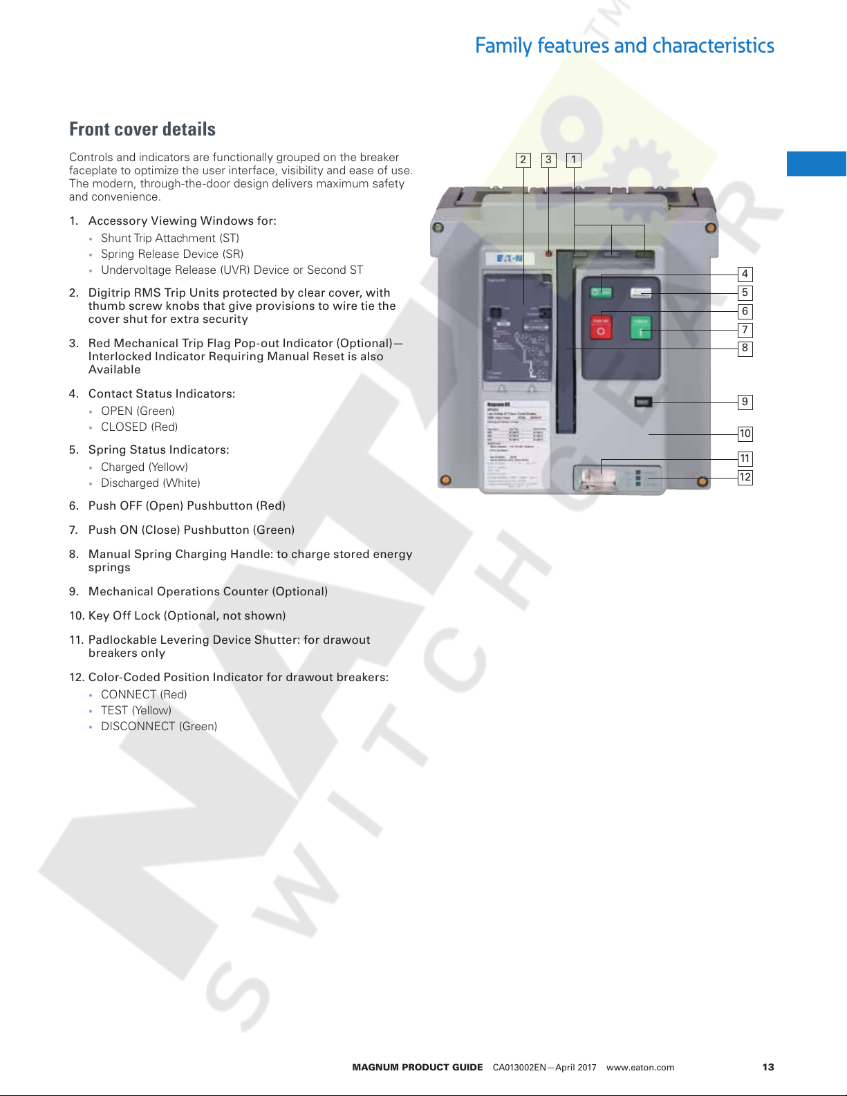
Controls and indicators are functionally grouped on the breaker
faceplate to optimize the user interface, visibility and ease of use.
The modern, through-the-door design delivers maximum safety
and convenience.
1. Accessor y Viewing Windows for:
• Shunt Trip Attachment (ST)
• Spring Release Device (SR)
• Undervoltage Release (UVR) Device or Second ST
2. Digitrip RMS Trip Units protected by clear cover, with
thumb screw knobs that give provisions to wire tie the
cover shut for extra security
3. Red Mechanical Trip Flag Pop-out Indicator (Optional)—
Interlocked Indicator Requiring Manual Reset is also
Available
4. Contact Status Indicators:
• OPEN (Green)
• CLOSED (Red)
5. Spring Status Indicators:
• Charged (Yellow)
• Discharged (White)
6. Push OFF (Open) Pushbutton (Red)
7. Push ON (Close) Pushbutton (Green)
8. Manual Spring Charging Handle: to charge stored energy
springs
9. Mechanical Operations Counter (Optional)
2 3 1
10
11
12
2
1
1
1
4
5
6
7
8
1
1
1
1
9
1
1
1
1
1
1
1
10. Key Off Lock (Optional, not shown)
11. Padlockable Levering Device Shutter: for drawout
breakers only
12. Color-Coded Position Indicator for drawout breakers:
• CONNECT (Red)
• TEST (Yellow)
• DISCONNECT (Green)
1
1
1
1
1
1
1
1
1
1
1
1
1
1
MAGNUM PRODUCT GUIDE CA013002EN—April 2017 www.eaton.com 13
Family features and characteristics
Courtesy of NationalSwitchgear.com
Construction characteristics
From the inside out, safety is of paramount importance with
2
special attention given to live parts insulation and segregation
between phases. Careful selection of materials, meticulous
assembly, rigorous testing, and unsurpassed experience make
1
Magnum a proven reliable product.
1
Rigid frame housing
1
Magnum circuit breakers use a rigid frame housing construction
1
of durable engineered thermoset composite resins.
•
1
1
1
1
1
1
1
1
1
1
1
1
1
1
1
1
1
1
1
1
1
1
1
Strong and lightweight material with strength to weight ratio
twice that of steel. Proven able to withstand high dynamic and
thermal stresses.
•
Excellent dielectric characteristics, resisting arc tracking.
Three piece construction
The 3-piece construction (rear housing, front housing, and cover)
provides support while isolating and insulating power conductors
•
A 2-piece case encloses current paths and arc chambers.
Chambers act to channel arc gases up and out during
interruption.
•
The operating mechanism and accessories sit on the front of
the case. Only the insulating front cover needs to be removed
to access mechanism and/or accessories .
•
The operating mechanism achieves a longer life as a result
of reduced frame deflection during operation along with stiff
component mounting.
Two-step stored energy mechanism
Magnum circuit breakers are equipped with a true 2-step stored
energy mechanism.
•
Closing springs can be charged manually or electrically.
•
5 to 7 downward strokes on the charging handle completes
charging process.
•
Mechanism provides for a complete OPEN – CLOSE – OPEN
cycle.
Unsurpassed performance design
The performance characteristics of the Magnum breaker
are attributed in many ways to a C-loop current path design
and movement. Contact fingers perform both the main and
arcing contact functions on different parts of the same finger.
A complete movable contact assembly is a combination of a
number of single contact fingers. The exact number of contact
fingers required depends upon the frame size and interrupting
rating of the breaker. Braided connectors (flexible shunts) are
used to attach each contact finger. The result is an efficient
and uniquely functional main contact system with the following
advantages:
•
Eliminate bolted joints reducing hot spots.
•
Reduced mounting space for primary contacts.
•
Smaller and lighter operating mechanism for longer life.
•
Higher interrupting and short time (withstand) ratings.
•
5-cycle or less closing.
•
Improved contact material.
•
Contact wear indicator for each primary contact structure.
•
Individually removable arc chambers insulate/isolate each pole.
•
Able to withstand high dynamic and thermal stresses.
Value added features
Magnum provides numerous other internal and external features
that further enhance the reliability, maintenance and safety of
this industry leading product offering. A number of additional
common features are highlighted below. See Section 7 for
trip units, and Section 8 for accessories, for more in-depth
information.
•
Available Arcflash Reduction Maintenance System™ on Digitrip
520MC and 1150, to lower personnel risk and PPE levels in the
arcflash boundary.
•
Field installable trip units, sensors and accessories.
•
Mechanical and electrical anti-pump features.
•
Easily removable arc chutes for inspection.
•
Common accessories for all frame sizes (electrical and
mechanical).
•
Automatic drawout primary shutters.
•
Conveniently located finger proof secondary contacts.
•
Will accommodate a variety of primary terminal types/
configurations.
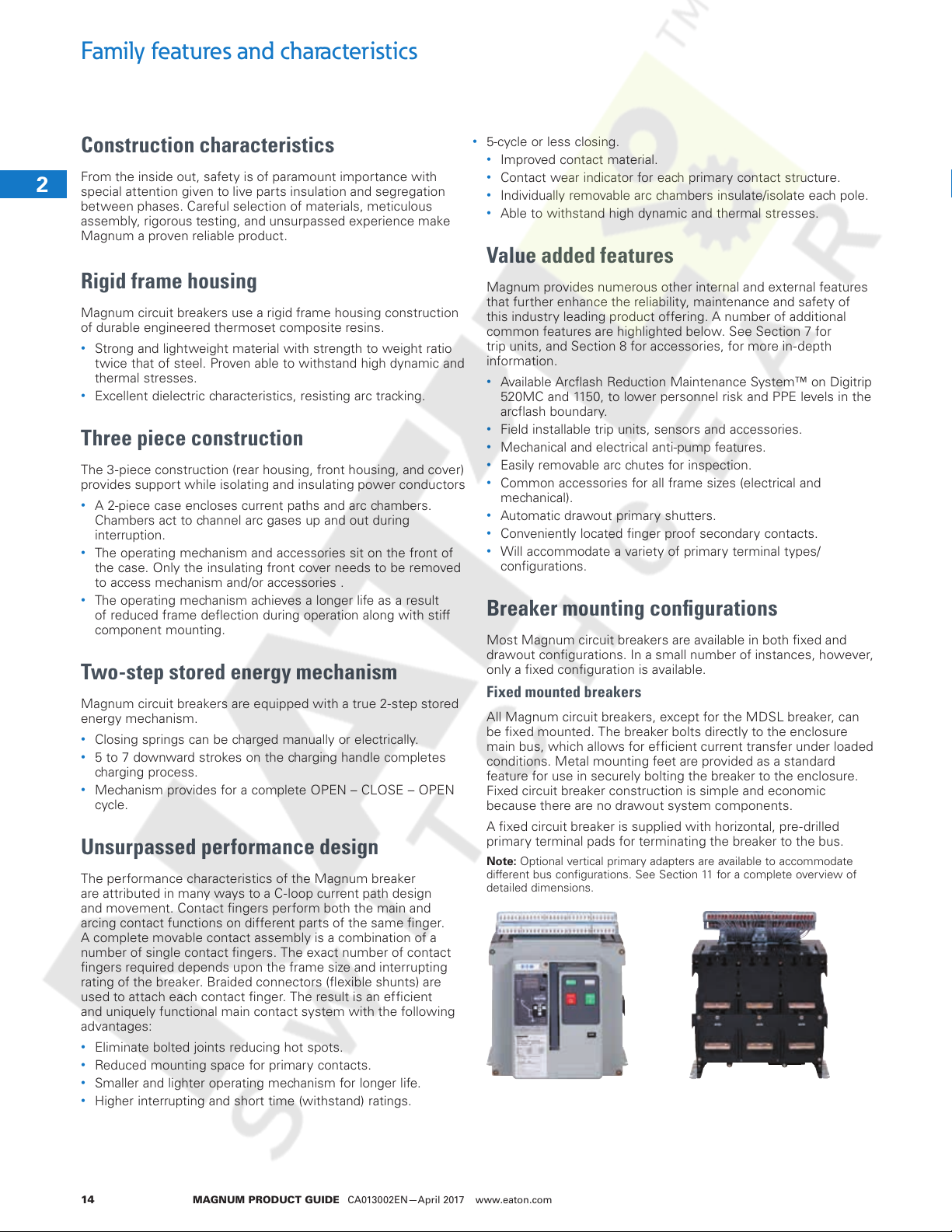
Breaker mounting configurations
Most Magnum circuit breakers are available in both fixed and
drawout configurations. In a small number of instances, however,
only a fixed configuration is available.
Fixed mounted breakers
All Magnum circuit breakers, except for the MDSL breaker, can
be fixed mounted. The breaker bolts directly to the enclosure
main bus, which allows for efficient current transfer under loaded
conditions. Metal mounting feet are provided as a standard
feature for use in securely bolting the breaker to the enclosure.
Fixed circuit breaker construction is simple and economic
because there are no drawout system components.
A fixed circuit breaker is supplied with horizontal, pre-drilled
primary terminal pads for terminating the breaker to the bus.
ote:N Optional vertical primary adapters are available to accommodate
different bus configurations. See Section 11 for a complete overview of
detailed dimensions.
1
MAGNUM PRODUCT GUIDE CA013002EN—April 2017 www.eaton.com14
Family features and characteristics
Courtesy of NationalSwitchgear.com
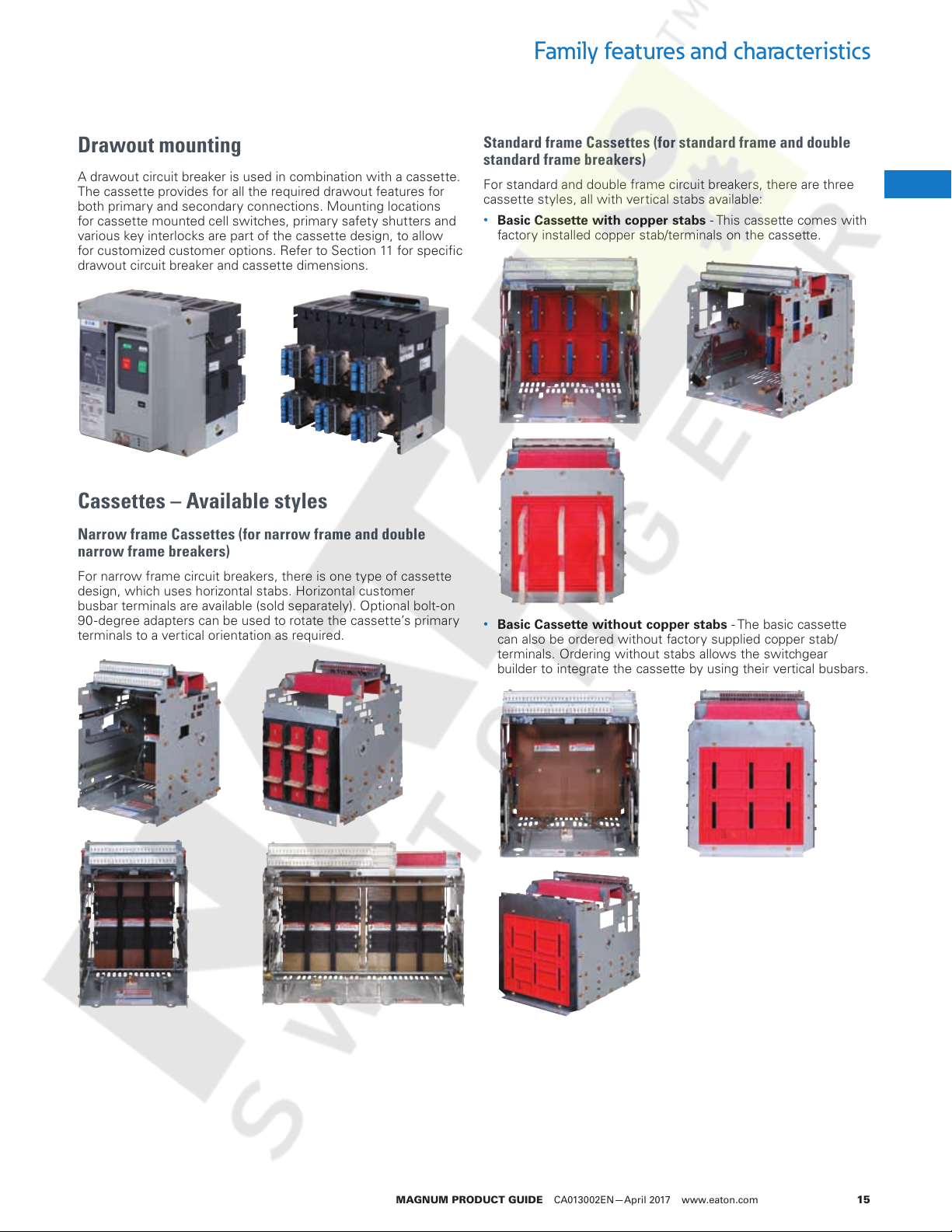
Drawout mounting
A drawout circuit breaker is used in combination with a cassette.
The cassette provides for all the required drawout features for
both primary and secondary connections. Mounting locations
for cassette mounted cell switches, primary safety shutters and
various key interlocks are part of the cassette design, to allow
for customized customer options. Refer to Section 11 for specific
drawout circuit breaker and cassette dimensions.
Cassettes – Available styles
Narrow frame Cassettes (for narrow frame and double
narrow frame breakers)
For narrow frame circuit breakers, there is one type of cassette
design, which uses horizontal stabs. Horizontal customer
busbar terminals are available (sold separately). Optional bolt-on
90 -degree adapters can be used to rotate the cassette’s primary
terminals to a vertical orientation as required.
Standard frame Cassettes (for standard frame and double
standard frame breakers)
For standard and double frame circuit breakers, there are three
cassette styles, all with vertical stabs available:
•
Basic Cassette with copper stabs - This cassette comes with
factory installed copper stab/terminals on the cassette.
•
Basic Cassette without copper stabs - The basic cassette
can also be ordered without factory supplied copper stab/
terminals. Ordering without stabs allows the switchgear
builder to integrate the cassette by using their vertical busbars.
2
1
1
1
1
1
1
1
1
1
1
1
1
1
1
1
1
1
1
1
1
1
1
1
1
1
1
1
1
MAGNUM PRODUCT GUIDE CA013002EN—April 2017 www.eaton.com 15
Family features and characteristics
Courtesy of NationalSwitchgear.com
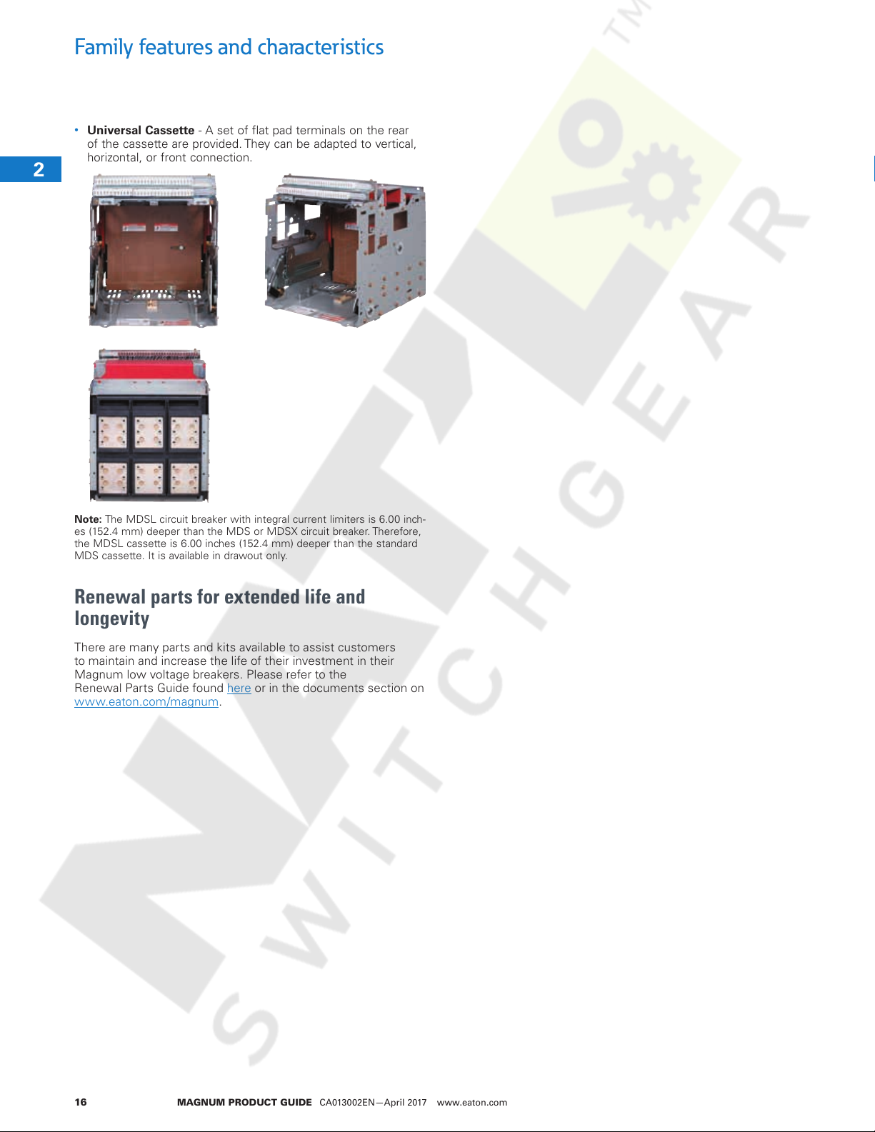
•
Universal Cassette - A set of flat pad terminals on the rear
of the cassette are provided. They can be adapted to vertical,
horizontal, or front connection.
2
1
1
1
1
1
1
1
1
1
1
1
1
ote:N The MDSL circuit breaker with integral current limiters is 6.00 inch-
es (152.4 mm) deeper than the MDS or MDSX circuit breaker. Therefore,
the MDSL cassette is 6.00 inches (152.4 mm) deeper than the standard
MDS cassette. It is available in drawout only.
1
Renewal parts for extended life and
1
longevity
1
There are many parts and kits available to assist customers
to maintain and increase the life of their investment in their
1
Magnum low voltage breakers. Please refer to the
Renewal Parts Guide found here or in the documents section on
1
www.eaton.com/magnum.
1
1
1
1
1
1
1
1
1
1
1
MAGNUM PRODUCT GUIDE CA013002EN—April 2017 www.eaton.com16
Standards and certifications
Courtesy of NationalSwitchgear.com
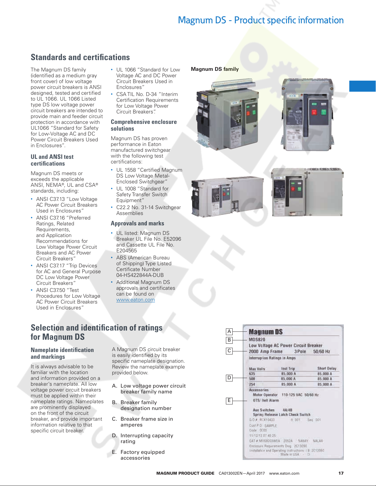
Magnum DS - Product specific information
The Magnum DS family
(identified as a medium gray
front cover) of low voltage
power circuit breakers is ANSI
designed, tested and certified
to UL 1066. UL 1066 Listed
type DS low voltage power
circuit breakers are intended to
provide main and feeder circuit
protection in accordance with
UL1066 “Standard for Safety
for Low-Voltage AC and DC
Power Circuit Breakers Used
in Enclosures”.
UL and ANSI test
certifications
Magnum DS meets or
exceeds the applicable
ANSI, NEMA
standards, including:
•
ANSI C37.13 “Low Voltage
AC Power Circuit Breakers
Used in Enclosures”
•
ANSI C37.16 “Preferred
Ratings, Related
Requirements,
and Application
Recommendations for
Low Voltage Power Circuit
Breakers and AC Power
Circuit Breakers”
•
ANSI C37.17 “Trip Devices
for AC and General Purpose
DC Low Voltage Power
Circuit Breakers”
•
ANSI C37.50 “Test
Procedures for Low Voltage
AC Power Circuit Breakers
Used in Enclosures”
®
, UL and CSA®
•
UL 1066 “Standard for Low
Voltage AC and DC Power
Circuit Breakers Used in
Enclosures”
•
CSA TIL No. D-34 ”Interim
Certification Requirements
for Low Voltage Power
Circuit Breakers”.
Comprehensive enclosure
solutions
Magnum DS has proven
performance in Eaton
manufactured switchgear
with the following test
certifications:
•
UL 1558 “Certified Magnum
DS Low Voltage Metal-
Enclosed Switchgear”
•
UL 1008 “Standard for
Safety Transfer Switch
Equipment”
•
C22.2 No. 31-14 Switchgear
Assemblies
Approvals and marks
•
UL listed: Magnum DS
Breaker UL File No. E52096
and Cassette UL File No.
E204565
•
ABS (American Bureau
of Shipping) Type Listed
Certificate Number
04-HS422844A-DUB
•
Additional Magnum DS
approvals and certificates
can be found on
www.eaton.com
Magnum DS family
3
1
1
1
1
1
1
1
1
1
1
1
1
1
1
1
1
1
Selection and identification of ratings
for Magnum DS
Nameplate identification
and markings
It is always advisable to be
familiar with the location
and information provided on a
breaker’s nameplate. All low
voltage power circuit breakers
must be applied within their
nameplate ratings. Nameplates
are prominently displayed
on the front of the circuit
breaker, and provide important
information relative to that
specific circuit breaker.
A Magnum DS circuit breaker
is easily identified by its
specific nameplate designation.
Review the nameplate example
provided below.
A. Low voltage power circuit
breaker family name
B. Breaker family
designation number
C. Breaker frame size in
amperes
D. Interrupting capacity
rating
E. Factory equipped
accessories
MAGNUM PRODUCT GUIDE CA013002EN—April 2017 www.eaton.com 17
A
B
C
1
1
1
1
D
1
1
E
1
1
1
1
Magnum DS - Product specific information
Courtesy of NationalSwitchgear.com
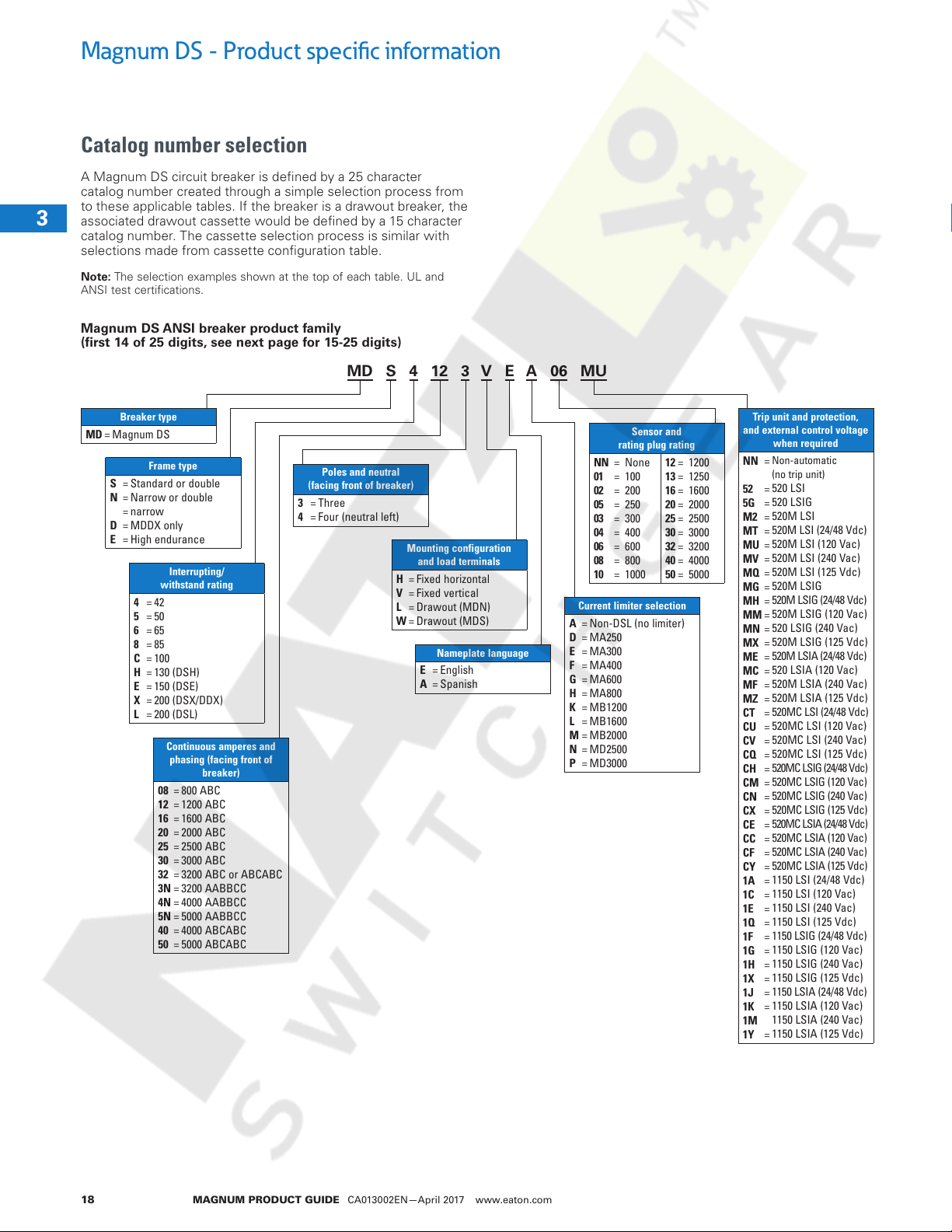
Catalog number selection
A Magnum DS circuit breaker is defined by a 25 character
catalog number created through a simple selection process from
to these applicable tables. If the breaker is a drawout breaker, the
associated drawout cassette would be defined by a 15 character
3
catalog number. The cassette selection process is similar with
selections made from cassette configuration table.
1
1
1
1
1
ote:N The selection examples shown at the top of each table. UL and
ANSI test certifications.
Magnum DS ANSI breaker product family
(first 14 of 25 digits, see next page for 15-25 digits)
MD S 4 12 3 V E A 06 MU
1
1
1
1
1
1
1
1
1
1
1
1
1
1
1
1
Breaker type
MD =Magnum DS
Frame type
S
=
Standard or double
N
=
Narrow or double
=
narrow
D
=
MDDX only
E
=
High endurance
4
=
42
5
=
50
6
=
65
8
=
85
C
=
100
H
=
130 (DSH)
E
=
150 (DSE)
X
=
200 (DSX/DDX)
L
=
200 (DSL)
Interrupting/
withstand rating
Continuous amperes and
phasing (facing front of
breaker)
08
=
800 ABC
12
=
1200 ABC
16
=
1600 ABC
20
=
2000 ABC
25
=
2500 ABC
30
=
3000 ABC
32
=
3200 ABC or ABCABC
3N
=
3200 AABBCC
4N
=
4000 AABBCC
5N
=
5000 AABBCC
40
=
4000 ABCABC
50
=
5000 ABCABC
Poles and neutral
(facing front of breaker)
34==Three
Four (neutral left)
Mounting configuration
and load terminals
H
=
Fixed horizontal
V
=
Fixed vertical
L
=
Drawout (MDN)
W
=
Drawout (MDS)
Nameplate language
EA==English
Spanish
Sensor and
rating plug rating
NN
=
None
01
=
100
02
=
200
05
=
250
03
=
300
04
=
400
06
=
600
08
=
800
10
=
1000
Current limiter selection
A
=
Non-DSL (no limiter)
D
=
MA250
E
=
MA300
F
=
MA400
G
=
MA600
H
=
MA800
K
=
MB1200
L
=
MB1600
M
=
MB2000
N
=
MD2500
P
=
MD3000
12
=
1200
13
=
1250
16
=
1600
20
=
2000
25
=
2500
30
=
3000
32
=
3200
40
=
4000
50
=
5000
1
1
1
Trip unit and protection,
and external control voltage
when required
Non-automatic
NN
=
(no trip unit)
520 LSI
52
=
520 LSIG
5G
=
520M LSI
M2
=
520M LSI (24/48 Vdc)
MT
=
520M LSI (120 Vac)
MU
=
520M LSI (240 Vac)
MV
=
520M LSI (125 Vdc)
MQ
=
520M LSIG
MG
=
520M LSIG (24/48 Vdc)
MH
=
520M LSIG (120 Vac)
MM
=
520 LSIG (240 Vac)
MN
=
520M LSIG (125 Vdc)
MX
=
520M LSIA (24/48 Vdc)
ME
=
520 LSIA (120 Vac)
MC
=
520M LSIA (240 Vac)
MF
=
520M LSIA (125 Vdc)
MZ
=
520MC LSI (24/48 Vdc)
CT
=
520MC LSI (120 Vac)
CU
=
520MC LSI (240 Vac)
CV
=
520MC LSI (125 Vdc)
CQ
=
520MC LSIG (24/48 Vdc)
CH
=
520MC LSIG (120 Vac)
CM
=
520MC LSIG (240 Vac)
CN
=
520MC LSIG (125 Vdc)
CX
=
520MC LSIA (24/48 Vdc)
CE
=
520MC LSIA (120 Vac)
CC
=
520MC LSIA (240 Vac)
CF
=
520MC LSIA (125 Vdc)
CY
=
1150 LSI (24/48 Vdc)
1A
=
1150 LSI (120 Vac)
1C
=
1150 LSI (240 Vac)
1E
=
1150 LSI (125 Vdc)
1Q
=
1150 LSIG (24/48 Vdc)
1F
=
1150 LSIG (120 Vac)
1G
=
1150 LSIG (240 Vac)
1H
=
1150 LSIG (125 Vdc)
1X
=
1150 LSIA (24/48 Vdc)
1J
=
1150 LSIA (120 Vac)
1K
=
1150 LSIA (240 Vac)
1M
1150 LSIA (125 Vdc)
1Y
=
1
1
1
MAGNUM PRODUCT GUIDE CA013002EN—April 2017 www.eaton.com18
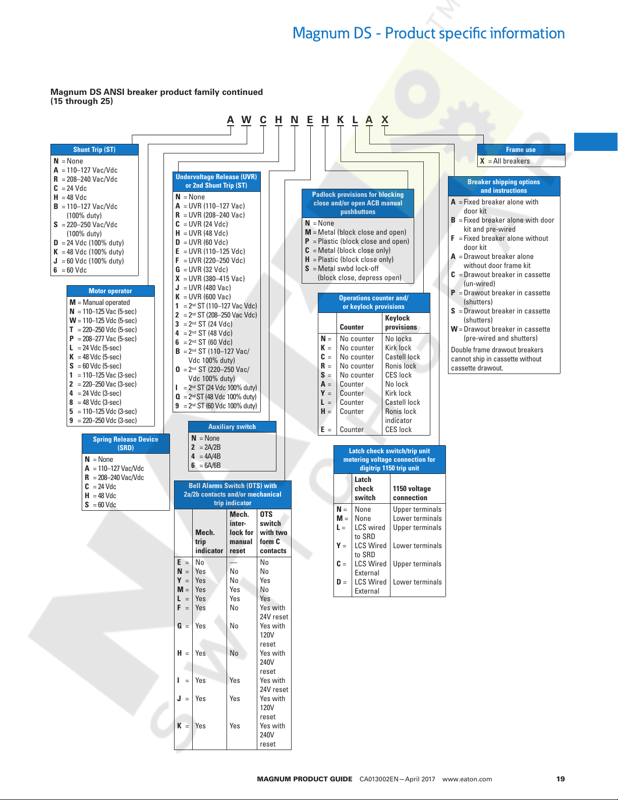
Magnum DS ANSI breaker product family continued
Courtesy of NationalSwitchgear.com
(15 through 25)
A W C H N E H K L A X
Magnum DS - Product specific information
Shunt Trip (ST)
N
=
None
A
=
110–127 Vac/Vdc
R
=
208–240 Vac/Vdc
C
=
24 Vdc
H
=
48 Vdc
B
=
110–127 Vac/Vdc
(100% duty)
S
=
220–250 Vac/Vdc
(100% duty)
D
=
24 Vdc (100% duty)
K
=
48 Vdc (100% duty)
J
=
60 Vdc (100% duty)
6
=
60 Vdc
Motor operator
M
=
Manual operated
N
=
110–125 Vac (5-sec)
W
=
110–125 Vdc (5-sec)
T
=
220–250 Vdc (5-sec)
P
=
208–277 Vac (5-sec)
L
=
24 Vdc (5-sec)
K
=
48 Vdc (5-sec)
S
=
60 Vdc (5-sec)
1
=
110–125 Vac (3-sec)
2
=
220–250 Vac (3-sec)
4
=
24 Vdc (3-sec)
8
=
48 Vdc (3-sec)
5
=
110–125 Vdc (3-sec)
9
=
220–250 Vdc (3-sec)
N
A
R
C
H
S
Spring Release Device
(SRD)
=
None
=
110–127 Vac/Vdc
=
208–240 Vac/Vdc
=
24 Vdc
=
48 Vdc
=
60 Vdc
Undervoltage Release (UVR)
or 2nd Shunt Trip (ST)
N
=
None
A
=
UVR (110–127 Vac)
R
=
UVR (208–240 Vac)
C
=
UVR (24 Vdc)
H
=
UVR (48 Vdc)
D
=
UVR (60 Vdc)
E
=
UVR (110–125 Vdc)
F
=
UVR (220–250 Vdc)
G
=
UVR (32 Vdc)
X
=
UVR (380–415 Vac)
J
=
UVR (480 Vac)
K
=
UVR (600 Vac)
1
=
2nd ST (110–127 Vac Vdc)
2
=
2nd ST (208–250 Vac Vdc)
3
=
2nd ST (24 Vdc)
4
=
2nd ST (48 Vdc)
6
=
2nd ST (60 Vdc)
B
=
2nd ST (110–127 Vac/
Vdc 100% duty)
O
=
2nd ST (220–250 Vac/
Vdc 100% duty)
I
=
2nd ST (24 Vdc 100% duty)
nd
Q
=
2
ST (48 Vdc 100% duty)
9
=
2nd ST (60 Vdc 100% duty)
Auxiliary switch
N
=
None
2
=
2A/2B
4
=
4A/4B
6
=
6A/6B
Bell Alarms Switch (OTS) with
2a/2b contacts and/or mechanical
trip indicator
Mech.
inter-
lock for
manual
reset
—
No
No
Yes
Yes
No
No
No
Yes
Yes
Yes
E
N
Y
M
L
F
G
H
I
J
K
=
=
=
=
=
=
=
=
=
=
=
Mech.
trip
indicator
No
Yes
Yes
Yes
Yes
Yes
Yes
Yes
Yes
Yes
Yes
OTS
switch
with two
form C
contacts
No
No
Yes
No
Yes
Yes with
24V reset
Yes with
120V
reset
Yes with
240V
reset
Yes with
24V reset
Yes with
120V
reset
Yes with
240V
reset
Padlock provisions for blocking
close and/or open ACB manual
pushbuttons
N
=
None
M
=
Metal (block close and open)
P
=
Plastic (block close and open)
C
=
Metal (block close only)
H
=
Plastic (block close only)
S
=
Metal swbd lock-off
(block close, depress open)
Operations counter and/
or keylock provisions
Counter
N
=
No counter
K
=
No counter
C
=
No counter
R
=
No counter
S
=
No counter
A
=
Counter
Y
=
Counter
L
=
Counter
H
=
Counter
E
=
Counter
Latch check switch/trip unit
metering voltage connection for
digitrip 1150 trip unit
Latch
check
switch
N =
None
M =
None
L =
LCS wired
to SRD
Y =
LCS Wired
to SRD
C =
LCS Wired
External
D =
LCS Wired
External
Keylock
provisions
No locks
Kirk lock
Castell lock
Ronis lock
CES lock
No lock
Kirk lock
Castell lock
Ronis lock
indicator
CES lock
1150 voltage
connection
Upper terminals
Lower terminals
Upper terminals
Lower terminals
Upper terminals
Lower terminals
Frame use
X = All breakers
Breaker shipping options
and instructions
A
=
Fixed breaker alone with
door kit
B
=
Fixed breaker alone with door
kit and pre-wired
F
=
Fixed breaker alone without
door kit
A
=
Drawout breaker alone
without door frame kit
C
=
Drawout breaker in cassette
(un-wired)
P
=
Drawout breaker in cassette
(shutters)
S
=
Drawout breaker in cassette
(shutters)
W
=
Drawout breaker in cassette
(pre-wired and shutters)
Double frame drawout breakers
cannot ship in cassette without
cassette drawout.
3
1
1
1
1
1
1
1
1
1
1
1
1
1
1
1
1
1
1
1
1
1
1
1
1
1
1
1
MAGNUM PRODUCT GUIDE CA013002EN—April 2017 www.eaton.com 19
Magnum DS - Product specific information
Courtesy of NationalSwitchgear.com
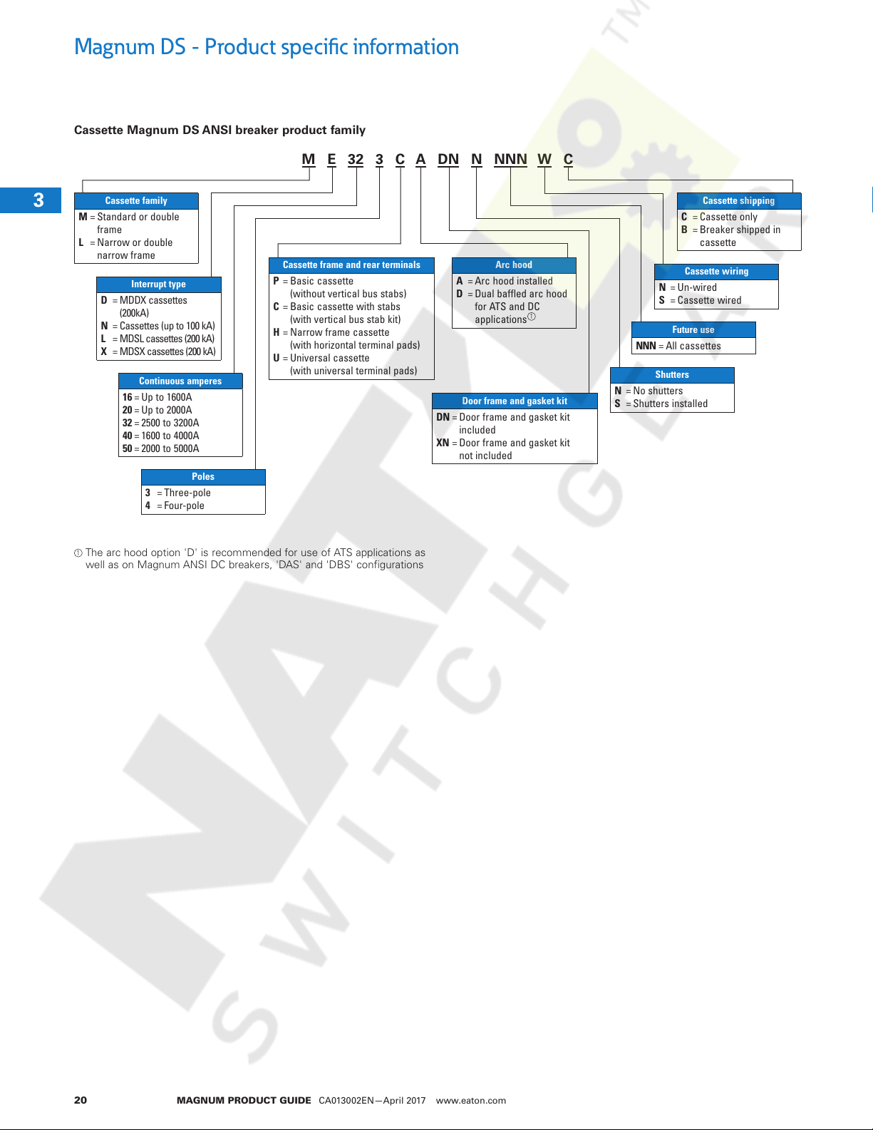
Cassette Magnum DS ANSI breaker product family
M E 32 3 C A DN N NNN W C
3
1
1
1
1
1
1
1
1
1
1
1
1
Cassette family
ML==Standard or double
frame
Narrow or double
narrow frame
Interrupt type
D
=
MDDX cassettes
(200kA)
N
=
Cassettes (up to 100 kA)
L
=
MDSL cassettes (200 kA)
X
=
MDSX cassettes (200 kA)
Continuous amperes
16
=
Up to 1600A
20
=
Up to 2000A
32
=
2500 to 3200A
40
=
1600 to 4000A
50
=
2000 to 5000A
Poles
34==Three-pole
Four-pole
1
The arc hood option 'D' is recommended for use of ATS applications as
well as on Magnum ANSI DC breakers, 'DAS' and 'DBS' configurations
Cassette frame and rear terminals
P
=
Basic cassette
(without vertical bus stabs)
C
=
Basic cassette with stabs
(with vertical bus stab kit)
H
=
Narrow frame cassette
(with horizontal terminal pads)
U
=
Universal cassette
(with universal terminal pads)
Arc hood
AD==Arc hood installed
Dual baffled arc hood
for ATS and DC
applications
Door frame and gasket kit
DNXN==Door frame and gasket kit
included
Door frame and gasket kit
not included
1
NS==Un-wired
NNN = All cassettes
Shutters
NS==No shutters
Shutters installed
Cassette shipping
CB==Cassette only
Breaker shipped in
cassette
Cassette wiring
Cassette wired
Future use
1
1
1
1
1
1
1
1
1
1
1
1
1
1
1
MAGNUM PRODUCT GUIDE CA013002EN—April 2017 www.eaton.com20
Magnum DS - Product specific information
Courtesy of NationalSwitchgear.com
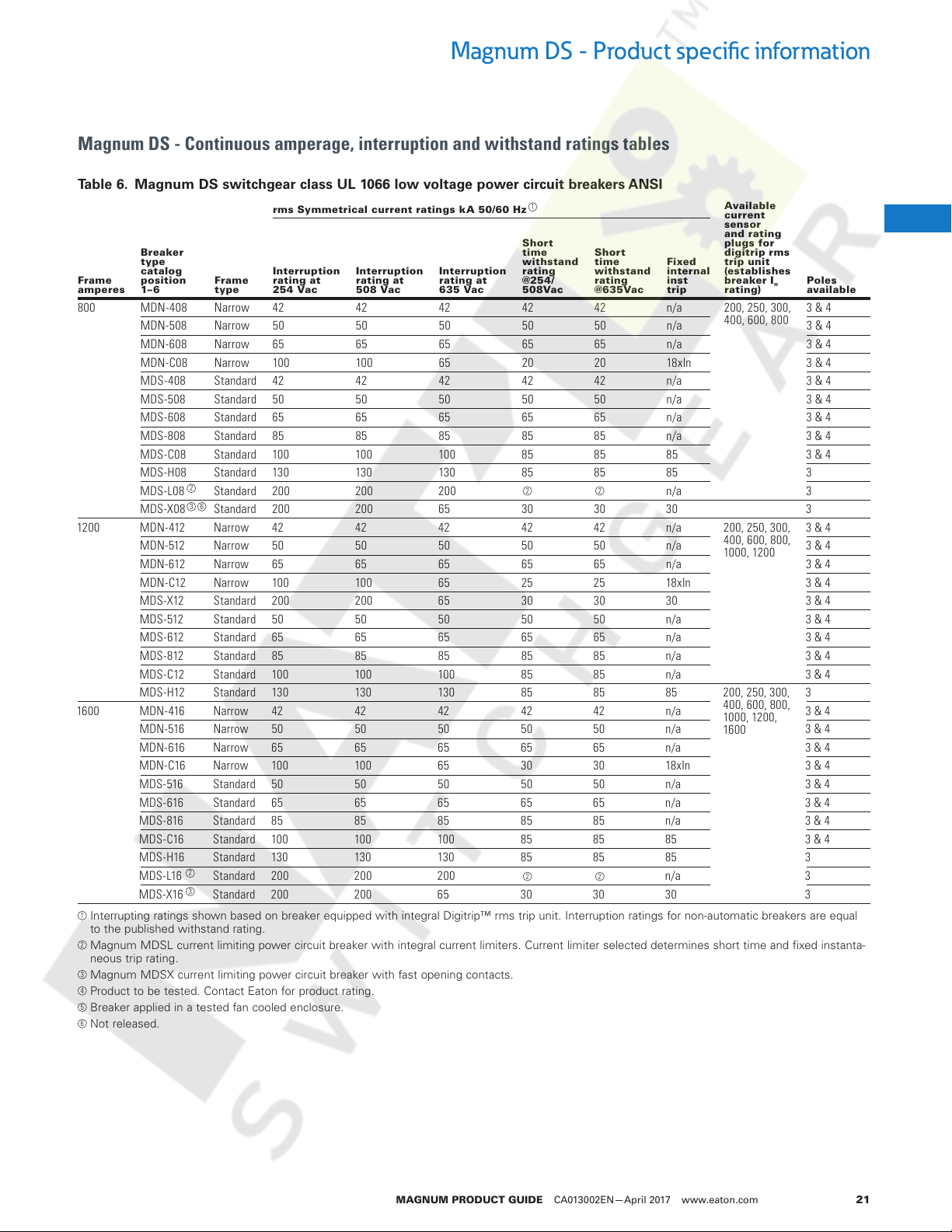
Magnum DS - Continuous amperage, interruption and withstand ratings tables
Table 6. Magnum DS switchgear class UL 1066 low voltage power circuit breakers ANSI
rms Symmetrical current ratings kA 50/60 Hz
Breaker
type
Frame
amperes
800 MDN-408 Narrow 42 42 42 42 42 n/a 200, 250, 300,
1200 MDN -412 Narrow 42 42 42 42 42 n/a 200, 250, 300,
1600 MDN-416 Narrow 42 42 42 42 42 n/a 3 & 4
1
Interrupting ratings shown based on breaker equipped with integral Digitrip™ rms trip unit. Interruption ratings for non-automatic breakers are equal
to the published withstand rating.
2
Magnum MDSL current limiting power circuit breaker with integral current limiters. Current limiter selected determines short time and fixed instanta-
neous trip rating.
3
Magnum MDSX current limiting power circuit breaker with fast opening contacts.
4
Product to be tested. Contact Eaton for product rating.
5
Breaker applied in a tested fan cooled enclosure.
6
Not released.
catalog
position
1–6
MDN-508 Narrow 50 50 50 50 50 n/a 3 & 4
MDN-608 Narrow 65 65 65 65 65 n/a 3 & 4
MDN-C08 Narrow 100 10 0 65 20 20 18xIn 3 & 4
MDS-408 Standard 42 42 42 42 42 n/a 3 & 4
MDS-508 Standard 50 50 50 50 50 n/a 3 & 4
MDS-608 Standard 65 65 65 65 65 n/a 3 & 4
MDS-808 Standard 85 85 85 85 85 n/a 3 & 4
MDS-C08 Standard 100 10 0 100 85 85 85 3 & 4
MDS-H08 Standard 130 130 13 0 85 85 85 3
MDS-L08 Standard 200 200 200 n/a 3
MDS-X08 Standard 200 200 65 30 30 30 3
MDN -512 Narrow 50 50 50 50 50 n/a 3 & 4
MDN -612 Narrow 65 65 65 65 65 n/a 3 & 4
MDN -C12 Narrow 100 100 65 25 25 18xIn 3 & 4
MDS -X12 Standard 200 200 65 30 30 30 3 & 4
MDS -512 Standard 50 50 50 50 50 n/a 3 & 4
MDS -612 Standard 65 65 65 65 65 n/a 3 & 4
MDS -812 Standard 85 85 85 85 85 n/a 3 & 4
MDS -C12 Standard 100 10 0 100 85 85 n/a 3 & 4
MDS -H12 Standard 130 130 130 85 85 85 200, 250, 30 0,
MDN-516 Narrow 50 50 50 50 50 n/a 3 & 4
MDN-616 Narrow 65 65 65 65 65 n/a 3 & 4
MDN-C16 Narrow 10 0 100 65 30 30 18xIn 3 & 4
MDS -516 Standard 50 50 50 50 50 n/a 3 & 4
MDS -616 Standard 65 65 65 65 65 n/a 3 & 4
MDS -816 Standard 85 85 85 85 85 n/a 3 & 4
MDS -C16 Standard 100 100 10 0 85 85 85 3 & 4
MDS -H16 Standard 130 130 130 85 85 85 3
MDS- L16 Standard 200 200 200 n/a 3
MDS -X16 Standard 200 200 65 30 30 30 3
2
3
2
3 6
Frame
type
Interruption
ratin g at
254 Vac
Interruption
ratin g at
508 Vac
Interruption
ratin g at
635 Vac
1
Shor t
time
withstand
ratin g
@254/
508 Vac
2 2
2 2
Shor t
time
withstand
ratin g
@6 35Va c
Fixed
internal
inst
trip
Available
current
sensor
and rating
plugs f or
digit rip rms
trip un it
(establishes
breaker I
rating)
400, 600, 800
400, 600, 800,
1000, 1200
400, 600, 800,
1000, 1200,
1600
n
Poles
available
3 & 4
3 & 4
3
3
1
1
1
1
1
1
1
1
1
1
1
1
1
1
1
1
1
1
1
1
1
1
1
1
1
1
1
MAGNUM PRODUCT GUIDE CA013002EN—April 2017 www.eaton.com 21
Magnum DS - Product specific information
Courtesy of NationalSwitchgear.com
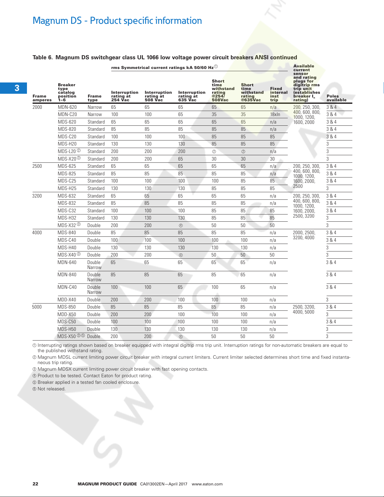
Table 6. Magnum DS switchgear class UL 1066 low voltage power circuit breakers ANSI continued
rms Symmetrical current ratings kA 50/60 Hz
Breaker
3
Frame
amperes
1
2000 MDN-620 Narrow 65 65 65 65 65 n/a 200, 250, 300,
1
1
1
1
2500 MDS-625 Standard 65 65 65 65 65 n/a 200, 250, 300,
1
1
3200 MDS-632 Standard 65 65 65 65 65 n/a 200, 250, 300,
1
1
1
4000 MDS-840 Double 85 85 85 85 85 n/a 2000, 2500,
1
1
1
1
1
1
5000 MDS-850 Double 85 85 85 85 85 n/a 2500, 3200,
1
1
1
1
1
1
1
Interrupting ratings shown based on breaker equipped with integral digitrip rms trip unit. Interruption ratings for non-automatic breakers are equal to
the published withstand rating.
2
Magnum MDSL current limiting power circuit breaker with integral current limiters. Current limiter selected determines short time and fixed instanta-
neous trip rating.
3
Magnum MDSX current limiting power circuit breaker with fast opening contacts.
4
Product to be tested. Contact Eaton for product rating.
5
Breaker applied in a tested fan cooled enclosure.
6
Not released.
type
catalog
position
1–6
MDN-C20 Narrow 100 10 0 65 35 35 18xIn 3 & 4
MDS-620 Standard 65 65 65 65 65 n/a 3 & 4
MDS-820 Standard 85 85 85 85 85 n/a 3 & 4
MDS-C20 Standard 100 10 0 100 85 85 85 3 & 4
MDS-H20 Standard 130 130 13 0 85 85 85 3
MDS-L20 Standard 200 200 200 n/a 3
MDS-X20 Standard 200 200 65 30 30 30 3
MDS-825 Standard 85 85 85 85 85 n/a 3 & 4
MDS-C25 Standard 100 10 0 100 100 85 85 3 & 4
MDS-H25 Standard 130 130 13 0 85 85 85 3
MDS-832 Standard 85 85 85 85 85 n/a 3 & 4
MDS-C32 Standard 100 10 0 100 85 85 85 3 & 4
MDS-H32 Standard 130 130 13 0 85 85 85 3
MDS-X32 Double 200 200 50 50 50 3
MDS-C40 Double 100 100 10 0 100 100 n/a 3 & 4
MDS-H40 Double 130 130 130 130 130 n/a 3
MDS-X40 Double 200 200 50 50 50 3
MDN-640 Double
MDN-840 Double
MDN-C40 Double
MDD-X40 Double 200 200 10 0 100 100 n/a 3
MDD-X50 Double 200 200 10 0 100 100 n/a 3
MDS-C50 Double 10 0 100 100 100 100 n/a 3 & 4
MDS-H50 Double 130 130 130 130 130 n/a 3
MDS-X50 Double 200 200 50 50 50 3
2
3
3
3
3 5
Frame
type
Narrow
Narrow
Narrow
Interruption
ratin g at
254 Vac
65 65 65 65 65 n/a 3 & 4
85 85 65 85 65 n/a 3 & 4
100 100 65 100 65 n/a 3 & 4
Interruption
ratin g at
508 Vac
Interruption
ratin g at
635 Vac
4
4
4
1
Shor t
time
withstand
ratin g
@254/
508 Vac
2 2
Shor t
time
withstand
ratin g
@6 35Va c
Fixed
internal
inst
trip
Available
current
sensor
and rating
plugs f or
digit rip rms
trip un it
(establishes
breaker I
rating)
400, 600, 800,
1000, 1200,
1600, 2000
400, 600, 800,
1000, 1200,
1600, 2000,
2500
400, 600, 800,
1000, 1200,
1600, 2000,
2500, 3200
3200, 4000
4000, 5000
n
Poles
available
3 & 4
3 & 4
3 & 4
3 & 4
3 & 4
1
1
1
1
1
MAGNUM PRODUCT GUIDE CA013002EN—April 2017 www.eaton.com22
Magnum DS - Product specific information
Courtesy of NationalSwitchgear.com
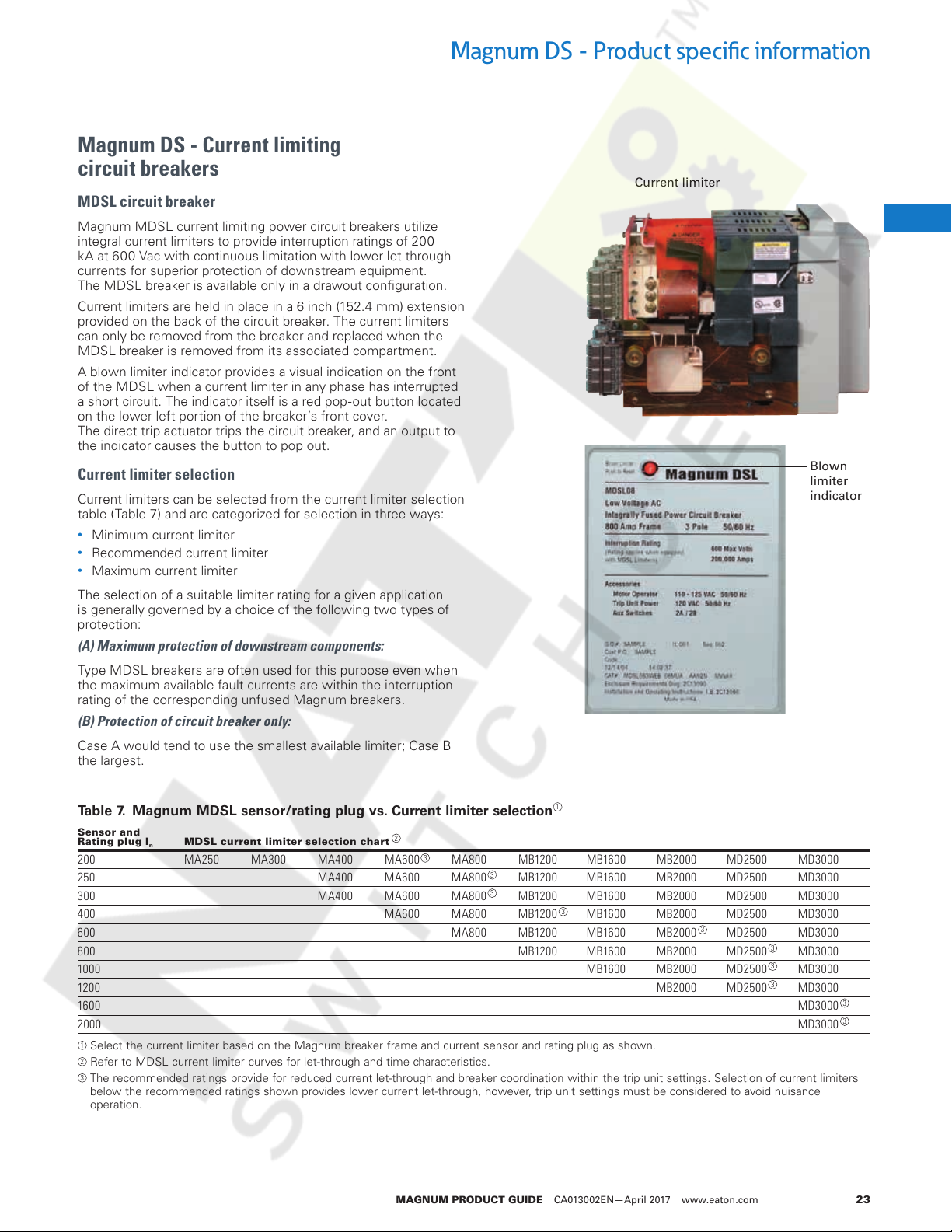
Magnum DS - Current limiting
circuit breakers
MDSL circuit breaker
Magnum MDSL current limiting power circuit breakers utilize
integral current limiters to provide interruption ratings of 200
kA at 600 Vac with continuous limitation with lower let through
currents for superior protection of downstream equipment.
The MDSL breaker is available only in a drawout configuration.
Current limiters are held in place in a 6 inch (152.4 mm) extension
provided on the back of the circuit breaker. The current limiters
can only be removed from the breaker and replaced when the
MDSL breaker is removed from its associated compartment.
A blown limiter indicator provides a visual indication on the front
of the MDSL when a current limiter in any phase has interrupted
a short circuit. The indicator itself is a red pop-out button located
on the lower left portion of the breaker’s front cover.
The direct trip actuator trips the circuit breaker, and an output to
the indicator causes the button to pop out.
Current limiter selection
Current limiters can be selected from the current limiter selection
table (Table 7) and are categorized for selection in three ways:
•
Minimum current limiter
•
Recommended current limiter
•
Maximum current limiter
The selection of a suitable limiter rating for a given application
is generally governed by a choice of the following two types of
protection:
(A) Maximum protection of downstream components:
Type MDSL breakers are often used for this purpose even when
the maximum available fault currents are within the interruption
rating of the corresponding unfused Magnum breakers.
(B) Protection of circuit breaker only:
Case A would tend to use the smallest available limiter; Case B
the largest.
Current limiter
Blown
limiter
indicator
3
1
1
1
1
1
1
1
1
1
1
1
1
1
1
1
1
Table 7. Magnum MDSL sensor/rating plug vs. Current limiter selection
Sensor and
Rating plug I
200 MA250 MA300 MA400 MA600 MA800 M B1200 MB16 00 MB2000 MD2500 MD3000
250 MA400 MA600 MA800 MB1200 MB16 00 MB2000 MD2500 MD3000
300 MA400 MA600 MA800 MB1200 MB16 00 MB2000 MD2500 MD3000
400 MA600 MA800 MB120 0 MB160 0 MB2000 MD2500 MD3000
600 MA800 MB1200 MB1600 MB2000 MD2500 MD3000
800 MB12 00 MB1600 MB2000 MD2500 MD3000
1000 MB16 00 MB2000 MD2500 MD3000
1200 MB2000 MD2500 MD3000
1600 MD3000
2000 MD3000
1
Select the current limiter based on the Magnum breaker frame and current sensor and rating plug as shown.
2
Refer to MDSL current limiter curves for let-through and time characteristics.
3
The recommended ratings provide for reduced current let-through and breaker coordination within the trip unit settings. Selection of current limiters
below the recommended ratings shown provides lower current let-through, however, trip unit settings must be considered to avoid nuisance
operation.
MDSL current limiter sele ctio n char t
n
1
2
3
3
3
3
3
3
3
3
3
3
MAGNUM PRODUCT GUIDE CA013002EN—April 2017 www.eaton.com 23
1
1
1
1
1
1
1
1
1
1
1
Magnum DS - Product specific information
Peak instantaneous let-through current kilo – amperes x 10
100
1000
10000
Courtesy of NationalSwitchgear.com
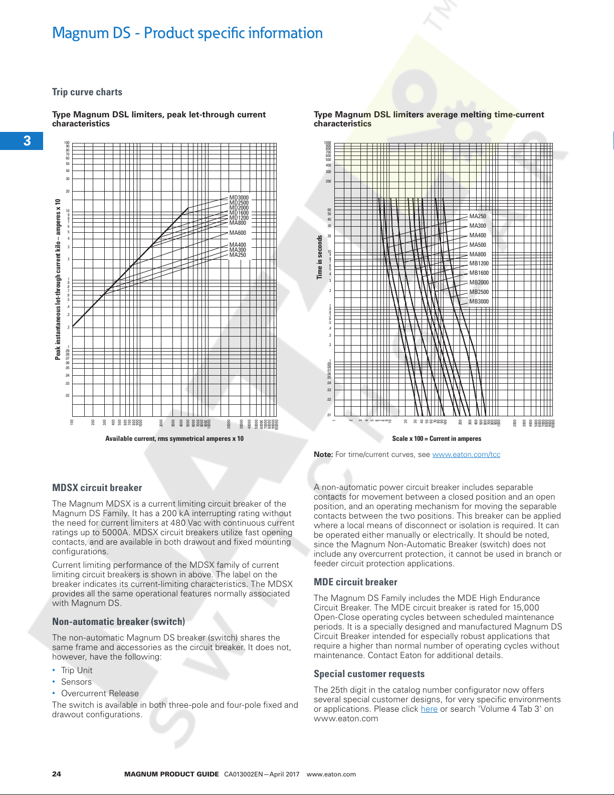
Trip curve charts
Type Magnum DSL limiters, peak let-through current
characteristics
3
1
1
1
1
1
1
1
1
1
1
1
90
80
70
60
50
40
30
20
10
9
8
7
6
5
4
3
2
1
.9
.8
.7
.6
.5
.4
.3
.2
.1
.09
.08
.07
.06
.05
.04
.03
.02
1
100
200
300
400
500
600
700
800
900
1000
2000
3000
4000
5000
6000
7000
1
8000
Available current, rms symmetrical amperes x 10
1
1
Type Magnum DSL limiters average melting time-current
characteristics
900
800
700
600
500
400
300
200
MD3000
MD2500
MD2000
MD1600
MD1200
MA800
MA600
MA400
MA300
MA250
9000
10000
20000
30000
40000
50000
70000
80000
90000
60000
100000
60
50
40
30
20
10
9
8
7
6
5
4
Time in seconds
3
2
1
.9
.8
.7
.6
.5
.4
.3
.2
.1
.09
.08
.07
.06
.05
.04
.03
.02
.01
1
2345678
9
10
20304050607080
MA250
MA300
MA400
MA500
MA800
MB1200
MB1600
MB2000
MB2500
MB3000
90
100
200
300
400
500
600
700
Scale x 100 = Current in amperes
ote:N For time/current curves, see www.eaton.com/tcc
800
900
1000
2000
3000
4000
5000
6000
7000
8000
9000
MDSX circuit breaker
1
The Magnum MDSX is a current limiting circuit breaker of the
1
Magnum DS Family. It has a 200 kA interrupting rating without
the need for current limiters at 4 80 Vac with continuous current
ratings up to 5000A. MDSX circuit breakers utilize fast opening
1
contacts, and are available in both drawout and fixed mounting
configurations.
1
Current limiting performance of the MDSX family of current
limiting circuit breakers is shown in above. The label on the
1
breaker indicates its current-limiting characteristics. The MDSX
provides all the same operational features normally associated
1
with Magnum DS.
1
Non-automatic breaker (switch)
The non-automatic Magnum DS breaker (switch) shares the
1
same frame and accessories as the circuit breaker. It does not,
however, have the following:
1
•
Trip Unit
•
1
1
Sensors
•
Overcurrent Release
The switch is available in both three-pole and four-pole fixed and
drawout configurations.
1
MAGNUM PRODUCT GUIDE CA013002EN—April 2017 www.eaton.com24
A non-automatic power circuit breaker includes separable
contacts for movement between a closed position and an open
position, and an operating mechanism for moving the separable
contacts between the two positions. This breaker can be applied
where a local means of disconnect or isolation is required. It can
be operated either manually or electrically. It should be noted,
since the Magnum Non-Automatic Breaker (switch) does not
include any overcurrent protection, it cannot be used in branch or
feeder circuit protection applications.
MDE circuit breaker
The Magnum DS Family includes the MDE High Endurance
Circuit Breaker. The MDE circuit breaker is rated for 15,000
Open-Close operating cycles between scheduled maintenance
periods. It is a specially designed and manufactured Magnum DS
Circuit Breaker intended for especially robust applications that
require a higher than normal number of operating cycles without
maintenance. Contact Eaton for additional details.
Special customer requests
The 25th digit in the catalog number configurator now offers
several special customer designs, for very specific environments
or applications. Please click here or search 'Volume 4 Tab 3' on
www.eaton.com
Standards and certifications
Courtesy of NationalSwitchgear.com
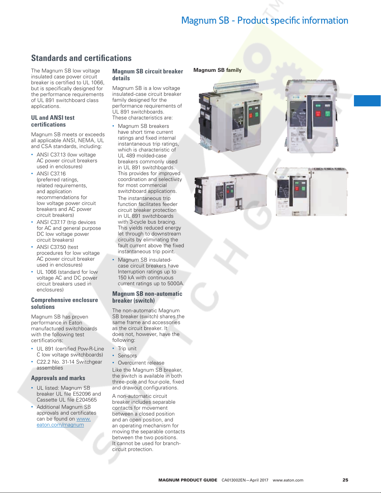
Magnum SB - Product specific information
The Magnum SB low voltage
insulated case power circuit
breaker is certified to UL 1066,
but is specifically designed for
the performance requirements
of UL 891 switchboard class
applications.
UL and ANSI test
certifications
Magnum SB meets or exceeds
all applicable ANSI, NEMA, UL
and CSA standards, including:
•
ANSI C37.13 (low voltage
AC power circuit breakers
used in enclosures)
•
ANSI C37.16
(preferred ratings,
related requirements,
and application
recommendations for
low voltage power circuit
breakers and AC power
circuit breakers)
•
ANSI C37.17 (trip devices
for AC and general purpose
DC low voltage power
circuit breakers)
•
ANSI C37.50 (test
procedures for low voltage
AC power circuit breaker
used in enclosures)
•
UL 1066 (standard for low
voltage AC and DC power
circuit breakers used in
enclosures)
Comprehensive enclosure
solutions
Magnum SB has proven
performance in Eaton
manufactured switchboards
with the following test
certifications:
•
UL 891 (certified Pow-R-Line
C low voltage switchboards)
•
C22.2 No. 31-14 Switchgear
assemblies
Approvals and marks
•
UL listed: Magnum SB
breaker UL file E52096 and
Cassette UL file E204565
•
Additional Magnum SB
approvals and certificates
can be found on www.
eaton.com/magnum
Magnum SB circuit breaker
details
Magnum SB is a low voltage
insulated- case circuit breaker
family designed for the
performance requirements of
UL 891 switchboards.
These characteristics are:
•
Magnum SB breakers
have short time current
ratings and fixed internal
instantaneous trip ratings,
which is characteristic of
UL 489 molded-case
breakers commonly used
in UL 891 switchboards.
This provides for improved
coordination and selectivity
for most commercial
switchboard applications.
The instantaneous trip
function facilitates feeder
circuit breaker protection
in UL 891 switchboards
with 3-cycle bus bracing.
This yields reduced energy
let through to downstream
circuits by eliminating the
fault current above the fixed
instantaneous trip point.
•
Magnum SB insulated-
case circuit breakers have
Interruption ratings up to
150 kA with continuous
current ratings up to 5000A.
Magnum SB non-automatic
breaker (switch)
The non-automatic Magnum
SB breaker (switch) shares the
same frame and accessories
as the circuit breaker. It
does not, however, have the
following:
•
Trip unit
•
Sensors
•
Overcurrent release
Like the Magnum SB breaker,
the switch is available in both
three-pole and four-pole, fixed
and drawout configurations.
A non-automatic circuit
breaker includes separable
contacts for movement
between a closed position
and an open position, and
an operating mechanism for
moving the separable contacts
between the two positions.
It cannot be used for branch-
circuit protection.
Magnum SB family
3
4
1
1
1
1
1
1
1
1
1
1
1
1
1
1
1
1
1
1
1
1
1
1
1
1
1
1
MAGNUM PRODUCT GUIDE CA013002EN—April 2017 www.eaton.com 25
Magnum SB - Product specific information
Courtesy of NationalSwitchgear.com
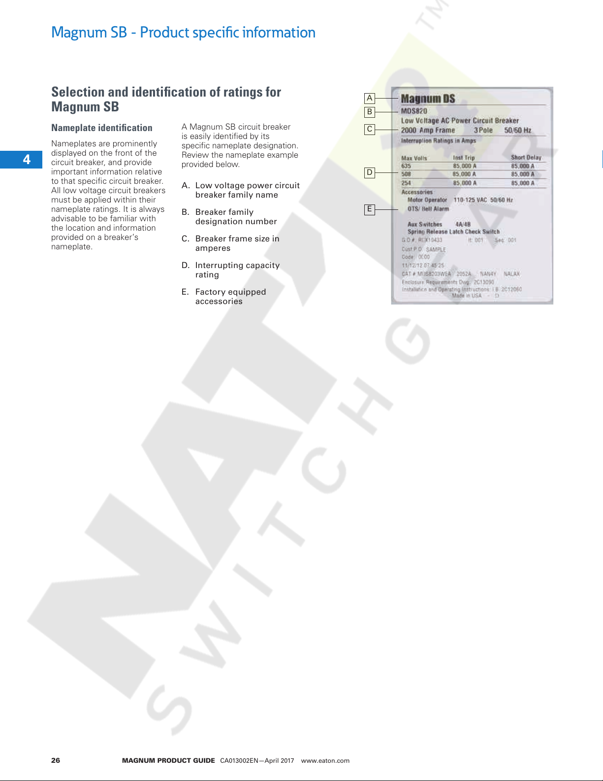
Selection and identification of ratings for
Magnum SB
Nameplate identification
3
Nameplates are prominently
displayed on the front of the
4
circuit breaker, and provide
important information relative
to that specific circuit breaker.
1
All low voltage circuit breakers
must be applied within their
1
nameplate ratings. It is always
advisable to be familiar with
1
the location and information
provided on a breaker’s
nameplate.
1
1
1
A Magnum SB circuit breaker
is easily identified by its
specific nameplate designation.
Review the nameplate example
provided below.
A. Low voltage power circuit
breaker family name
B. Breaker family
designation number
C. Breaker frame size in
amperes
D. Interrupting capacity
rating
E. Factory equipped
accessories
1
1
1
1
A
B
C
D
E
1
1
1
1
1
1
1
1
1
1
1
1
1
1
1
1
MAGNUM PRODUCT GUIDE CA013002EN—April 2017 www.eaton.com26

Magnum SB - Product specific information
Courtesy of NationalSwitchgear.com
Catalog number selection
Just like the Magnum DS, the Magnum SB circuit breaker is
defined & ordered by a 25 character catalog number created
through a simple selection process from two configuration tables.
If the breaker is a drawout breaker, the associated cassette
would be defined by a 15 character catalog number. The cassette
selection process is similar to that of the circuit breaker.
ote:N The selection examples shown at the top of each table, and that all
combinations are not possible.
3
4
1
Magnum SB breaker product family (first 14 of 25 digits, see next page for 15-25 digits)
SB S 4 12 3 V E A 06 MU
Breaker type
SB = Magnum switchboard
NN
Frame type
S
=
Standard or double
N
=
Narrow or double
=
narrow
D
=
MDDX only
E
=
High endurance
withstand rating
4
=
42
5
=
50
6
=
65
8
=
85
C
=
100
H
=
130 (DSH)
E
=
150 (DSE)
X
=
200 (DSX/DDX)
L
=
200 (DSL)
Continuous amperes and
08
12
16
20
25
30
32
3N
4N
5N
40
50
Interrupting/
phasing (facing front of
breaker)
=
800 ABC
=
1200 ABC
=
1600 ABC
=
2000 ABC
=
2500 ABC
=
3000 ABC
=
3200 ABC or ABCABC
=
3200 AABBCC
=
4000 AABBCC
=
5000 AABBCC
=
4000 ABCABC
=
5000 ABCABC
Poles and neutral
(facing front of breaker)
34==Three
Four (neutral left)
Mounting configuration
and load terminals
H
=
Fixed horizontal
V
=
Fixed vertical
L
=
Drawout (SBN)
W
=
Drawout (SBS)
Nameplate language
EA==English
Spanish
=
01
=
02
=
05
=
03
=
04
=
06
=
08
=
10
=
Current limiter selection
A
=
Non-DSL (no limiter)
D
=
MA250
E
=
MA300
F
=
MA400
G
=
MA600
H
=
MA800
K
=
MB1200
L
=
MB1600
M
=
MB2000
N
=
MD2500
P
=
MD3000
Sensor and
rating plug rating
None
12
100
200
250
300
400
600
800
1000
=
13
=
16
=
20
=
25
=
30
=
32
=
40
=
50
=
1200
1250
1600
2000
2500
3000
3200
4000
5000
Trip unit and protection,
and external control voltage
when required
Non-automatic
NN
=
(no trip unit)
520 LSI
52
=
520 LSIG
5G
=
520M LSI
M2
=
520M LSI (24/48 Vdc)
MT
=
520M LSI (120 Vac)
MU
=
520M LSI (240 Vac)
MV
=
520M LSI (125 Vdc)
MQ
=
520M LSIG
MG
=
520M LSIG (24/48 Vdc)
MH
=
520M LSIG (120 Vac)
MM
=
520 LSIG (240 Vac)
MN
=
520M LSIG (125 Vdc)
MX
=
520M LSIA (24/48 Vdc)
ME
=
520 LSIA (120 Vac)
MC
=
520M LSIA (240 Vac)
MF
=
520M LSIA (125 Vdc)
MZ
=
520MC LSI (24/48 Vdc)
CT
=
520MC LSI (120 Vac)
CU
=
520MC LSI (240 Vac)
CV
=
520MC LSI (125 Vdc)
CQ
=
520MC LSIG (24/48 Vdc)
CH
=
520MC LSIG (120 Vac)
CM
=
520MC LSIG (240 Vac)
CN
=
520MC LSIG (125 Vdc)
CX
=
520MC LSIA (24/48 Vdc)
CE
=
520MC LSIA (120 Vac)
CC
=
520MC LSIA (240 Vac)
CF
=
520MC LSIA (125 Vdc)
CY
=
1150 LSI (24/48 Vdc)
1A
=
1150 LSI (120 Vac)
1C
=
1150 LSI (240 Vac)
1E
=
1150 LSI (125 Vdc)
1Q
=
1150 LSIG (24/48 Vdc)
1F
=
1150 LSIG (120 Vac)
1G
=
1150 LSIG (240 Vac)
1H
=
1150 LSIG (125 Vdc)
1X
=
1150 LSIA (24/48 Vdc)
1J
=
1150 LSIA (120 Vac)
1K
=
1150 LSIA (240 Vac)
1M
1150 LSIA (125 Vdc)
1Y
=
1
1
1
1
1
1
1
1
1
1
1
1
1
1
1
1
1
1
1
1
1
1
1
1
1
MAGNUM PRODUCT GUIDE CA013002EN—April 2017 www.eaton.com 27
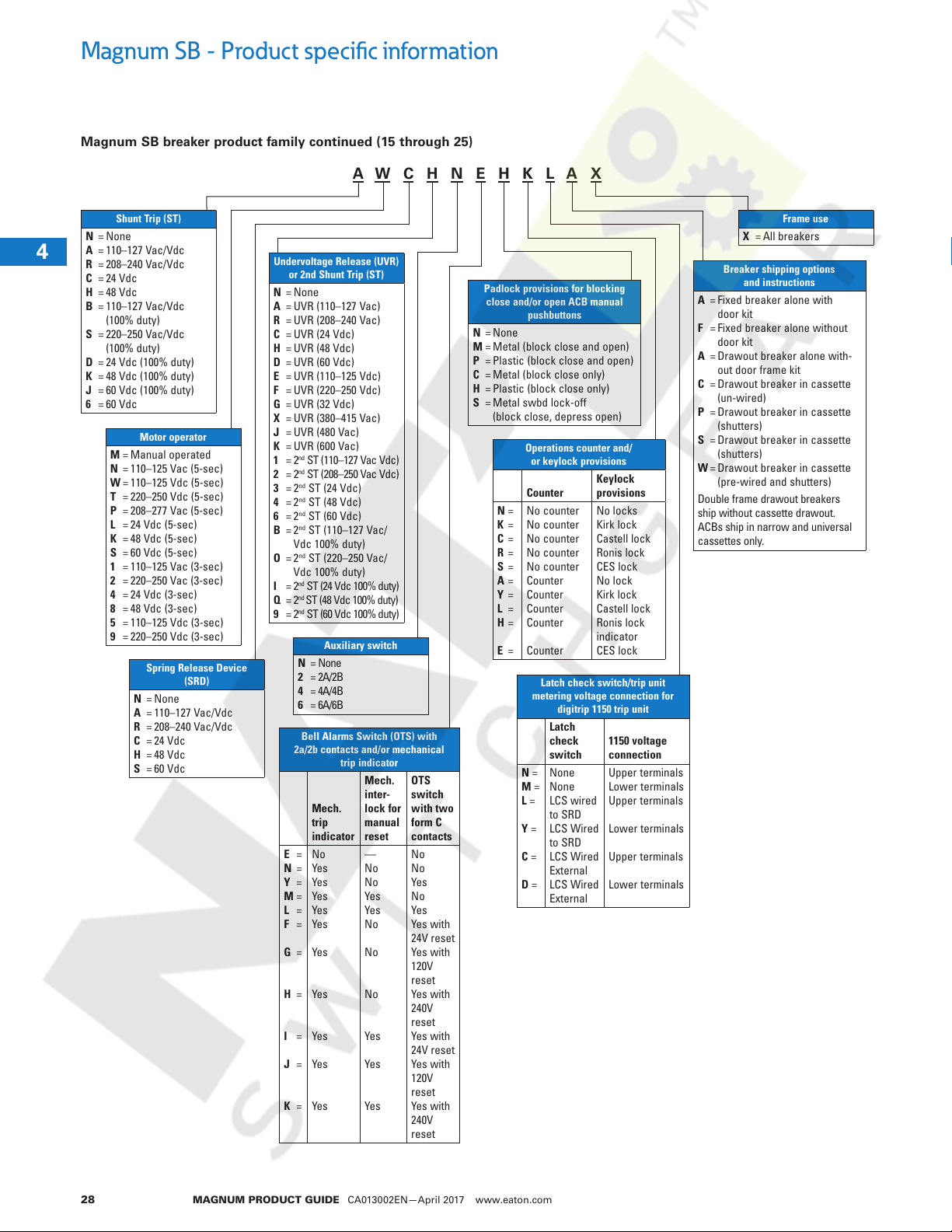
Magnum SB - Product specific information
Courtesy of NationalSwitchgear.com
Magnum SB breaker product family continued (15 through 25)
A W C H N E H K L A X
3
4
1
1
1
1
1
1
1
1
1
1
1
1
1
1
1
1
1
1
1
1
1
1
1
1
1
1
Shunt Trip (ST)
N
=
None
A
=
110–127 Vac/Vdc
R
=
208–240 Vac/Vdc
C
=
24 Vdc
H
=
48 Vdc
B
=
110–127 Vac/Vdc
(100% duty)
S
=
220–250 Vac/Vdc
(100% duty)
D
=
24 Vdc (100% duty)
K
=
48 Vdc (100% duty)
J
=
60 Vdc (100% duty)
6
=
60 Vdc
Motor operator
M
=
Manual operated
N
=
110–125 Vac (5-sec)
W
=
110–125 Vdc (5-sec)
T
=
220–250 Vdc (5-sec)
P
=
208–277 Vac (5-sec)
L
=
24 Vdc (5-sec)
K
=
48 Vdc (5-sec)
S
=
60 Vdc (5-sec)
1
=
110–125 Vac (3-sec)
2
=
220–250 Vac (3-sec)
4
=
24 Vdc (3-sec)
8
=
48 Vdc (3-sec)
5
=
110–125 Vdc (3-sec)
9
=
220–250 Vdc (3-sec)
N
A
R
C
H
S
Spring Release Device
(SRD)
=
None
=
110–127 Vac/Vdc
=
208–240 Vac/Vdc
=
24 Vdc
=
48 Vdc
=
60 Vdc
Undervoltage Release (UVR)
or 2nd Shunt Trip (ST)
N
=
None
A
=
UVR (110–127 Vac)
R
=
UVR (208–240 Vac)
C
=
UVR (24 Vdc)
H
=
UVR (48 Vdc)
D
=
UVR (60 Vdc)
E
=
UVR (110–125 Vdc)
F
=
UVR (220–250 Vdc)
G
=
UVR (32 Vdc)
X
=
UVR (380–415 Vac)
J
=
UVR (480 Vac)
K
=
UVR (600 Vac)
1
=
2nd ST (110–127 Vac Vdc)
2
=
2nd ST (208–250 Vac Vdc)
3
=
2nd ST (24 Vdc)
4
=
2nd ST (48 Vdc)
6
=
2nd ST (60 Vdc)
B
=
2nd ST (110–127 Vac/
Vdc 100% duty)
O
=
2nd ST (220–250 Vac/
Vdc 100% duty)
I
=
2nd ST (24 Vdc 100% duty)
nd
Q
=
2
ST (48 Vdc 100% duty)
9
=
2nd ST (60 Vdc 100% duty)
Auxiliary switch
N
=
None
2
=
2A/2B
4
=
4A/4B
6
=
6A/6B
Bell Alarms Switch (OTS) with
2a/2b contacts and/or mechanical
E
N
Y
M
L
F
G
H
I
J
K
=
=
=
=
=
=
=
=
=
=
=
trip indicator
Mech.
trip
indicator
No
Yes
Yes
Yes
Yes
Yes
Yes
Yes
Yes
Yes
Yes
Mech.
inter-
lock for
manual
reset
—
No
No
Yes
Yes
No
No
No
Yes
Yes
Yes
OTS
switch
with two
form C
contacts
No
No
Yes
No
Yes
Yes with
24V reset
Yes with
120V
reset
Yes with
240V
reset
Yes with
24V reset
Yes with
120V
reset
Yes with
240V
reset
Padlock provisions for blocking
close and/or open ACB manual
pushbuttons
N
=
None
M
=
Metal (block close and open)
P
=
Plastic (block close and open)
C
=
Metal (block close only)
H
=
Plastic (block close only)
S
=
Metal swbd lock-off
(block close, depress open)
Operations counter and/
or keylock provisions
Counter
N
=
No counter
K
=
No counter
C
=
No counter
R
=
No counter
S
=
No counter
A
=
Counter
Y
=
Counter
L
=
Counter
H
=
Counter
E
=
Counter
Latch check switch/trip unit
metering voltage connection for
digitrip 1150 trip unit
Latch
check
switch
N =
None
M =
None
L =
LCS wired
to SRD
Y =
LCS Wired
to SRD
C =
LCS Wired
External
D =
LCS Wired
External
Keylock
provisions
No locks
Kirk lock
Castell lock
Ronis lock
CES lock
No lock
Kirk lock
Castell lock
Ronis lock
indicator
CES lock
1150 voltage
connection
Upper terminals
Lower terminals
Upper terminals
Lower terminals
Upper terminals
Lower terminals
Breaker shipping options
A
=
Fixed breaker alone with
door kit
F
=
Fixed breaker alone without
door kit
A
=
Drawout breaker alone with-
out door frame kit
C
=
Drawout breaker in cassette
(un-wired)
P
=
Drawout breaker in cassette
(shutters)
S
=
Drawout breaker in cassette
(shutters)
W
=
Drawout breaker in cassette
(pre-wired and shutters)
Double frame drawout breakers
ship without cassette drawout.
ACBs ship in narrow and universal
cassettes only.
Frame use
X = All breakers
and instructions
MAGNUM PRODUCT GUIDE CA013002EN—April 2017 www.eaton.com28
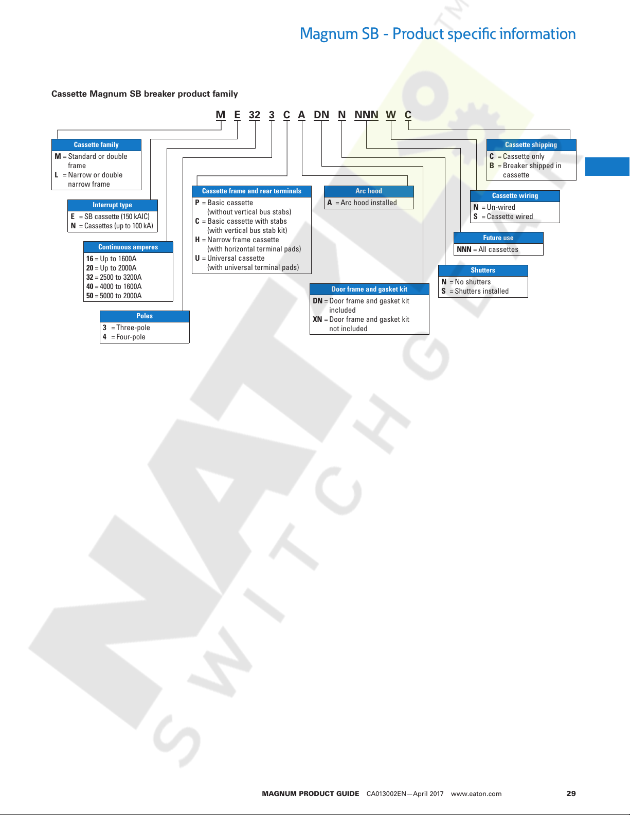
Cassette Magnum SB breaker product family
Courtesy of NationalSwitchgear.com
M E 32 3 C A DN N NNN W C
Magnum SB - Product specific information
Cassette family
ML==Standard or double
frame
Narrow or double
narrow frame
Interrupt type
EN==SB cassette (150 kAIC)
Cassettes (up to 100 kA)
Continuous amperes
16
=
Up to 1600A
20
=
Up to 2000A
32
=
2500 to 3200A
40
=
4000 to 1600A
50
=
5000 to 2000A
34==Three-pole
Four-pole
Poles
Cassette frame and rear terminals
P
=
Basic cassette
(without vertical bus stabs)
C
=
Basic cassette with stabs
(with vertical bus stab kit)
H
=
Narrow frame cassette
(with horizontal terminal pads)
U
=
Universal cassette
(with universal terminal pads)
Arc hood
A = Arc hood installed
Door frame and gasket kit
DNXN==Door frame and gasket kit
included
Door frame and gasket kit
not included
NS==Un-wired
NNN = All cassettes
Shutters
NS==No shutters
Shutters installed
Cassette shipping
CB==Cassette only
Breaker shipped in
cassette
Cassette wiring
Cassette wired
Future use
3
4
1
1
1
1
1
1
1
1
1
1
1
1
1
1
1
1
1
1
1
1
1
1
1
1
1
1
MAGNUM PRODUCT GUIDE CA013002EN—April 2017 www.eaton.com 29
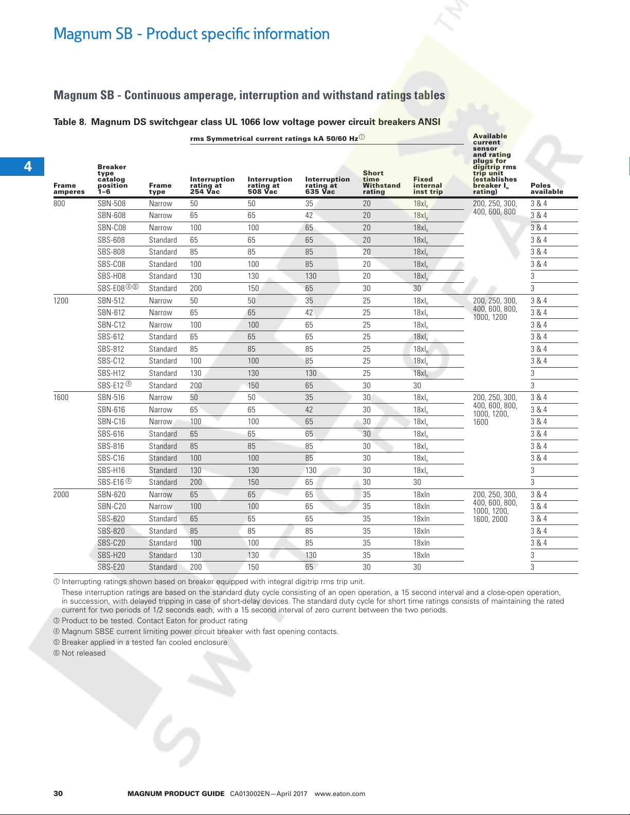
Magnum SB - Product specific information
Courtesy of NationalSwitchgear.com
Magnum SB - Continuous amperage, interruption and withstand ratings tables
Table 8. Magnum DS switchgear class UL 1066 low voltage power circuit breakers ANSI
3
rms Symmetrical current ratings kA 50/60 Hz
4
Frame
1
amperes
800 SBN-508 Narrow 50 50 35 20 18xI
1
1
1
1
1200 SBN-512 Narrow 50 50 35 25 18x I
1
1
1
1
1
1600 SBN-516 Narrow 50 50 35 30 18 xI
1
1
1
1
2000 SBN-620 Narrow 65 65 65 35 18xIn 200, 250, 300,
1
1
1
1
1
Interrupting ratings shown based on breaker equipped with integral digitrip rms trip unit.
1
1
1
1
These interruption ratings are based on the standard duty cycle consisting of an open operation, a 15 second interval and a close-open operation,
in succession, with delayed tripping in case of short-delay devices. The standard duty cycle for short time ratings consists of maintaining the rated
current for two periods of 1/2 seconds each, with a 15 second interval of zero current between the two periods.
3
Product to be tested. Contact Eaton for product rating
4
Magnum SBSE current limiting power circuit breaker with fast opening contacts.
5
Breaker applied in a tested fan cooled enclosure
6
Not released
Breaker
type
catalog
position
1–6
SBN-608 Narrow 65 65 42 20 18xI
SBN-C08 Narrow 100 100 65 20 18 xI
SBS-608 Standard 65 65 65 20 18x I
SBS-808 Standard 85 85 85 20 18xI
SBS-C08 Standard 100 100 85 20 18xI
SBS-H08 Standard 13 0 130 13 0 20 18xI
SBS-E08 Standard 200 150 65 30 30 3
SBN-612 Narrow 65 65 42 25 18x I
SBN-C12 Narrow 100 10 0 65 25 18xI
SBS- 612 Standard 65 65 65 25 18xI
SBS- 812 Standard 85 85 85 25 18x I
SBS-C12 Standard 100 100 85 25 18x I
SBS-H12 Standard 130 13 0 130 25 18 xI
SBS-E12 Standard 200 150 65 30 30 3
SBN -616 Narrow 65 65 42 30 18xI
SBN -C16 Narrow 10 0 100 65 30 18xI
SBS-616 Standard 65 65 65 30 18xI
SBS-816 Standard 85 85 85 30 18xI
SBS-C16 Standard 100 10 0 85 30 18xI
SBS-H16 Standard 130 130 13 0 30 18x I
SBS-E16 Standard 200 150 65 30 30 3
SBN-C20 Narrow 100 100 65 35 18 xIn 3 & 4
SBS-620 Standard 65 65 65 35 18x In 3 & 4
SBS-820 Standard 85 85 85 35 18xIn 3 & 4
SBS-C20 Standard 100 100 85 35 18xIn 3 & 4
SBS-H20 Standard 130 130 130 35 18xIn 3
SBS-E20 Standard 200 150 65 30 30 3
Frame
type
4
6
4
4
Interruption
ratin g at
254 Vac
Interruption
ratin g at
508 Vac
Interruption
ratin g at
635 Vac
1
Shor t
time
Withstand
rating
Fixed
internal
inst trip
n
n
n
n
n
n
n
n
n
n
n
n
n
n
n
n
n
n
n
n
n
Available
current
sensor
and rating
plugs f or
digit rip rms
trip un it
(establishes
breaker I
rating)
200, 250, 30 0,
400, 600, 800
200, 250, 30 0,
400, 600, 800,
1000, 1200
200, 250, 30 0,
400, 600, 800,
1000, 1200,
1600
400, 600, 800,
1000, 1200,
1600, 2000
n
Poles
available
3 & 4
3 & 4
3 & 4
3 & 4
3 & 4
3 & 4
3
3 & 4
3 & 4
3 & 4
3 & 4
3 & 4
3 & 4
3
3 & 4
3 & 4
3 & 4
3 & 4
3 & 4
3 & 4
3
3 & 4
1
1
1
1
MAGNUM PRODUCT GUIDE CA013002EN—April 2017 www.eaton.com30
 Loading...