

Eaton Magnum DS Instruction Leaflet
Instruction Leaet IL019107EN
Effective October 2015
Magnum DST switchgear terminal boots
for cable connections—installation
m WARNING
(1) ONLY QUALIFIED ELECTRICAL PERSONNEL SHOULD
BE PERMITTED TO WORK ON THE EQUIPMENT.
(2) DO NOT ATTEMPT TO INSTALL OR PERFORM
MAINTENANCE ON THE EQUIPMENT WHILE
ENERGIZED. ALWAYS VERIFY THAT NO VOLTAGE
IS PRESENT BEFORE PROCEEDING.
(3) ALWAYS DE-ENERGIZE PRIMARY AND SECONDARY
CIRCUITS IF A CIRCUIT BREAKER CANNOT BE
REMOVED TO A SAFE WORK LOCATION.
(4) DRAWOUT CIRCUIT BREAKERS SHOULD BE LEVERED
[RACKED] OUT TO THE DISCONNECT POSITION.
FAILURE TO FOLLOW THESE STEPS FOR ALL
PROCEDURES DESCRIBED IN THIS INSTRUCTION
LEAFLET COULD RESULT IN DEATH, BODILY INJURY,
OR PROPERTY DAMAGE.
General
Care should be exercised during installation to
minimize cuts and gaps in the boot material for
maximum coverage of the connection.
Required tools and supplies
•
Heavy-duty box cutter knife or similar
•
Plastic cable wire-ties
Installation of insulated
terminal boots
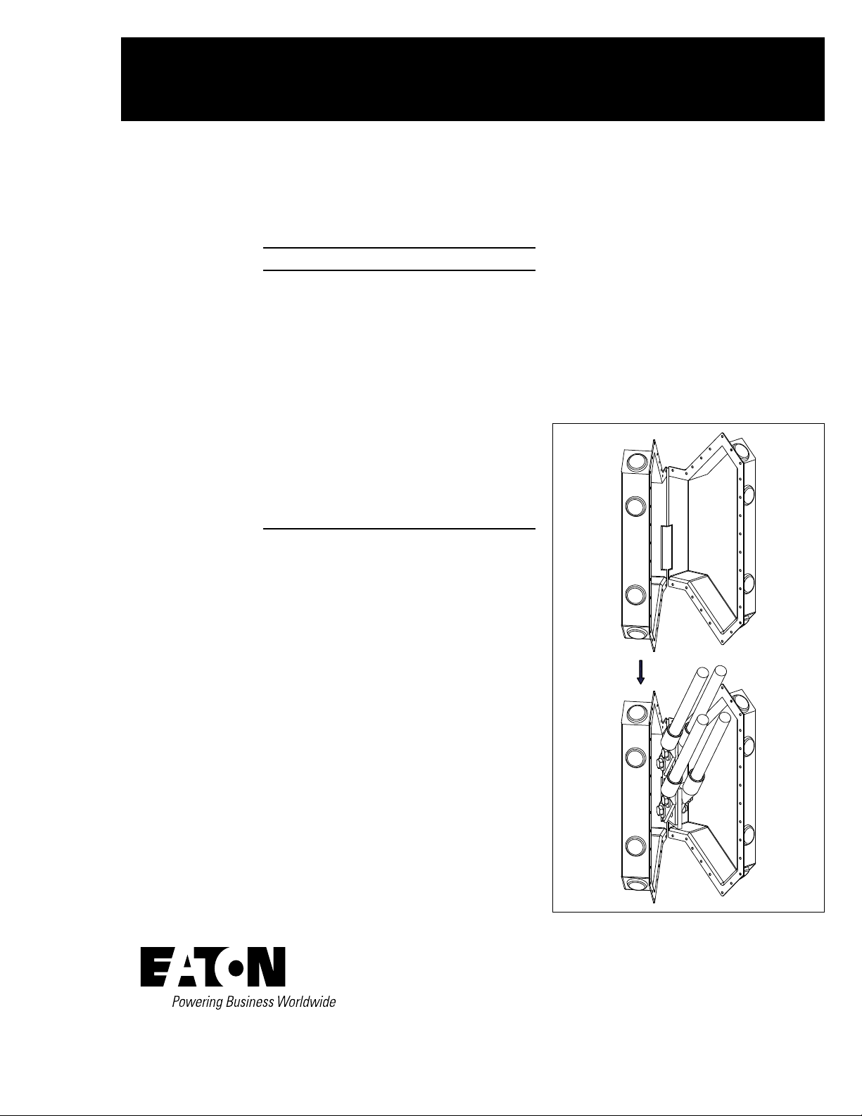
Step 1
As shown in Figure 1, open the “clam-shell”
shaped boot with the “hinge” area away from the
cable path. Flex and install the boot so that the
opening in the boot will surround the conductor
between the glass-polyester conductor support
and the cables. Orient the boot so that the
terminal adapter copper bar will be encased inside.
Parts provided
Each shipment shall contain one terminal boot per
phase for each circuit. Boots vary in size based on
the number of lugs/cables per terminal adapter.
The illustrations herein represent only one size,
but all items are installed in like manner.
Figure 1. Step 1
Instruction Leaet IL019107EN
Effective October 2015
Magnum DS switchgear terminal boots
for cable connections—installation
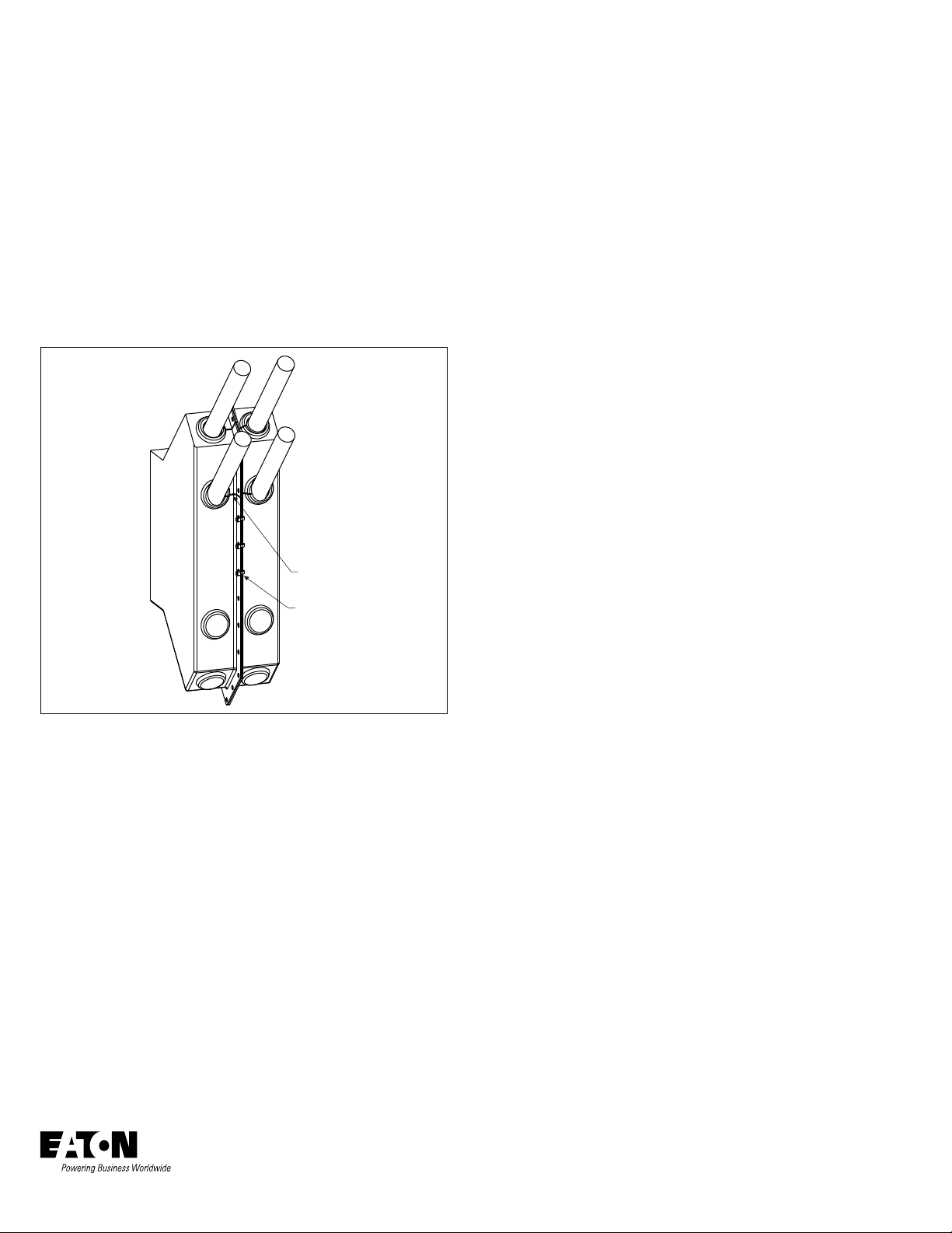
Step 2
As shown in Figure 2, the openings for each cable must be cut into
the boot at installation. Using the raised areas as a guide, cut an
opening for the passage of each cable. Also, cut a slit between the
cable opening and the center flange, to permit insertion of the cable
into the boot. Unused raised areas (cable access points) will remain
as boots. Boots are designed for multiple cable options and for
universal fit whether cables are going up (as shown) or down.
Step 3
As shown in Figure 2, following encasing of the cables in the boot,
close the seam with plastic wire ties in each hole provided along the
perimeter of the boot. The exposed copper and terminal connections
should be effectively isolated inside the boot.
Step 2
Disclaimer of warranties and
limitation of liability
The information, recommendations, descriptions, and safety
notations in this document are based on Eaton’s experience and
judgment, and may not cover all contingencies. If further information
is required, an Eaton sales office should be consulted.
Sale of the product shown in this literature is subject to the terms
and conditions outlined in appropriate Eaton selling policies or other
contractual agreement between Eaton and the purchaser.
THERE ARE NO UNDERSTANDINGS, AGREEMENTS,
WARRANTIES, EXPRESSED OR IMPLIED, INCLUDING
WARRANTIES OF FITNESS FOR A PARTICULAR PURPOSE OR
MERCHANTABILITY, OTHER THAN THOSE SPECIFICALLY SET
OUT IN ANY EXISTING CONTRACT BETWEEN THE PARTIES.
ANY SUCH CONTRACT STATES THE ENTIRE OBLIGATION OF
EATON. THE CONTENTS OF THIS DOCUMENT SHALL NOT
BECOME PART OF OR MODIFY ANY CONTRACT BETWEEN
THE PARTIES.
In no event will Eaton be responsible to the purchaser or user in
contract, in tort (including negligence), strict liability, or otherwise
for any special, indirect, incidental, or consequential damage or
loss whatsoever, including but not limited to damage or loss of
use of equipment, plant or power system, cost of capital, loss of
power, additional expenses in the use of existing power facilities,
or claims against the purchaser or user by its customers resulting
from the use of the information, recommendations, and descriptions
contained herein.
The information contained in this manual is subject to change
without notice.
Figure 2. Steps 2 and 3
Step 3
Eaton
1000 Eaton Boulevard
Cleveland, OH 44122
United States
Eaton.com
© 2015 Eaton
All Rights Reserved
Printed in USA
Publication No. IL019107EN / Z17345
October 2015
Eaton is a registered trademark.
All other trademarks are property
of their respective owners.
 Loading...