

EATON GVX9000 User Guide
GVX9000 AF Drives
User Manual
New Information
June 2006
MN04000001E For more information visit: www.EatonElectrical.com


Important Notice – Please Read
The product discussed in this literature is subject to terms and conditions
outlined in Eaton Electrical Inc. selling policies. The sole source
governing the rights and remedies of any purchaser of this equipment is
the relevant Eaton Electrical Inc. selling policy.
NO WARRANTIES, EXPRESS OR IMPLIED, INCLUDING WARRANTIES OF
FITNESS FOR A PARTICULAR PURPOSE OR MERCHANTABILITY, OR
WARRANTIES ARISING FROM COURSE OF DEALING OR USAGE OF
TRADE, ARE MADE REGARDING THE INFORMATION,
RECOMMENDATIONS AND DESCRIPTIONS CONTAINED HEREIN. In no
event will Eaton Electrical Inc. be responsible to the purchaser or user in
contract, in tort (including negligence), strict liability or otherwise for any
special, indirect, incidental or consequential damage or loss whatsoever,
including but not limited to damage or loss of use of equipment, plant or
power system, cost of capital, loss of power, additional expenses in the
use of existing power facilities, or claims against the purchaser or user by
its customers resulting from the use of the information,
recommendations and descriptions contained herein.
The information contained in this manual is subject to change without
notice.
Cover Photo: Eaton GVX9000 Drives
GVX9000 User Manual i

This page intentionally left blank.
ii GVX9000 User Manual

Table of Contents
LIST OF FIGURES . . . . . . . . . . . . . . . . . . . . . . . . . . . . . . . . . . . . . . . . . . . . . . . . . vi
LIST OF TABLES . . . . . . . . . . . . . . . . . . . . . . . . . . . . . . . . . . . . . . . . . . . . . . . . . . viii
SAFETY MESSAGES . . . . . . . . . . . . . . . . . . . . . . . . . . . . . . . . . . . . . . . . . . . . . . ix
Definitions and Symbols . . . . . . . . . . . . . . . . . . . . . . . . . . . . . . . . . . . . . . . . ix
Hazardous High Voltage . . . . . . . . . . . . . . . . . . . . . . . . . . . . . . . . . . . . . . . . . ix
High Voltage, Warnings and Cautions . . . . . . . . . . . . . . . . . . . . . . . . . . . . . . x
CHAPTER 1 — INTRODUCTION . . . . . . . . . . . . . . . . . . . . . . . . . . . . . . . . . . . . . 1-1
How to Use This Manual . . . . . . . . . . . . . . . . . . . . . . . . . . . . . . . . . . . . . . . . 1-2
Intended Audience . . . . . . . . . . . . . . . . . . . . . . . . . . . . . . . . . . . . . . . . . . . . . 1-3
Conventions Used in This Manual . . . . . . . . . . . . . . . . . . . . . . . . . . . . . . . . . 1-3
Warranty and Liability Information . . . . . . . . . . . . . . . . . . . . . . . . . . . . . . . . 1-4
Related Publications . . . . . . . . . . . . . . . . . . . . . . . . . . . . . . . . . . . . . . . . . . . . 1-4
CHAPTER 2 — OVERVIEW OF THE GVX9000 DRIVE . . . . . . . . . . . . . . . . . . . . 2-1
Receiving and Inspection . . . . . . . . . . . . . . . . . . . . . . . . . . . . . . . . . . . . . . . . 2-2
Nameplate Information . . . . . . . . . . . . . . . . . . . . . . . . . . . . . . . . . . . . . . . 2-2
Catalog Number . . . . . . . . . . . . . . . . . . . . . . . . . . . . . . . . . . . . . . . . . . . . . 2-3
Style Number . . . . . . . . . . . . . . . . . . . . . . . . . . . . . . . . . . . . . . . . . . . . . . . 2-4
External Parts and Label Locations . . . . . . . . . . . . . . . . . . . . . . . . . . . . . . . . 2-4
Digital Keypad Operation . . . . . . . . . . . . . . . . . . . . . . . . . . . . . . . . . . . . . . . . 2-5
CHAPTER 3 — STORAGE AND INSTALLATION . . . . . . . . . . . . . . . . . . . . . . . . 3-1
Storage . . . . . . . . . . . . . . . . . . . . . . . . . . . . . . . . . . . . . . . . . . . . . . . . . . . . . . . 3-2
Environment . . . . . . . . . . . . . . . . . . . . . . . . . . . . . . . . . . . . . . . . . . . . . . . . . . 3-2
Operation . . . . . . . . . . . . . . . . . . . . . . . . . . . . . . . . . . . . . . . . . . . . . . . . . . 3-2
Storage . . . . . . . . . . . . . . . . . . . . . . . . . . . . . . . . . . . . . . . . . . . . . . . . . . . . 3-2
Transportation . . . . . . . . . . . . . . . . . . . . . . . . . . . . . . . . . . . . . . . . . . . . . . 3-2
Pollution Degree . . . . . . . . . . . . . . . . . . . . . . . . . . . . . . . . . . . . . . . . . . . . 3-2
Mounting Area . . . . . . . . . . . . . . . . . . . . . . . . . . . . . . . . . . . . . . . . . . . . . . . . 3-3
Wiring . . . . . . . . . . . . . . . . . . . . . . . . . . . . . . . . . . . . . . . . . . . . . . . . . . . . . . . . 3-4
Applicable Codes . . . . . . . . . . . . . . . . . . . . . . . . . . . . . . . . . . . . . . . . . . . . . . 3-4
Basic Wiring Diagram . . . . . . . . . . . . . . . . . . . . . . . . . . . . . . . . . . . . . . . . . . . 3-5
External Wiring . . . . . . . . . . . . . . . . . . . . . . . . . . . . . . . . . . . . . . . . . . . . . . . . 3-8
Control Terminal Wiring (Factory Settings) . . . . . . . . . . . . . . . . . . . . . . . . . 3-10
Main Circuit Wiring . . . . . . . . . . . . . . . . . . . . . . . . . . . . . . . . . . . . . . . . . . . . . 3-11
Wiring Notes . . . . . . . . . . . . . . . . . . . . . . . . . . . . . . . . . . . . . . . . . . . . . . . . . . 3-17
Motor Operation Precautions . . . . . . . . . . . . . . . . . . . . . . . . . . . . . . . . . . . . . 3-18
GVX9000 User Manual iii

Table of Contents
CHAPTER 4 — START-UP PROCEDURES . . . . . . . . . . . . . . . . . . . . . . . . . . . . . . 4-1
Step-by-Step Installation . . . . . . . . . . . . . . . . . . . . . . . . . . . . . . . . . . . . . . . . 4-2
Mounting Location . . . . . . . . . . . . . . . . . . . . . . . . . . . . . . . . . . . . . . . . . . 4-2
Inverter Mounting . . . . . . . . . . . . . . . . . . . . . . . . . . . . . . . . . . . . . . . . . . . 4-4
Wiring Preparation . . . . . . . . . . . . . . . . . . . . . . . . . . . . . . . . . . . . . . . . . . 4-4
Wire Sizes . . . . . . . . . . . . . . . . . . . . . . . . . . . . . . . . . . . . . . . . . . . . . . . . . . 4-5
Fuses and Circuit Breakers . . . . . . . . . . . . . . . . . . . . . . . . . . . . . . . . . . . . . . . 4-6
Fusing . . . . . . . . . . . . . . . . . . . . . . . . . . . . . . . . . . . . . . . . . . . . . . . . . . . . . 4-6
Manual Motor Starters/UL489 Circuit Breakers . . . . . . . . . . . . . . . . . . . 4-6
Wiring the Inverter to Incoming Power . . . . . . . . . . . . . . . . . . . . . . . . . . 4-9
Wiring the Motor to the Inverter Output . . . . . . . . . . . . . . . . . . . . . . . . . 4-10
Power-Up Test . . . . . . . . . . . . . . . . . . . . . . . . . . . . . . . . . . . . . . . . . . . . . . 4-11
Powering the Inverter . . . . . . . . . . . . . . . . . . . . . . . . . . . . . . . . . . . . . . . . 4-12
CHAPTER 5 — DESCRIPTIONS OF PARAMETER SETTINGS . . . . . . . . . . . . . . 5-1
Viewing and Changing Parameter Settings . . . . . . . . . . . . . . . . . . . . . . . . . 5-2
Parameter Groups . . . . . . . . . . . . . . . . . . . . . . . . . . . . . . . . . . . . . . . . . . . . . . 5-4
Group 20 — Easy Mode Settings . . . . . . . . . . . . . . . . . . . . . . . . . . . . . . . . . . 5-5
Group 30 — Inputs . . . . . . . . . . . . . . . . . . . . . . . . . . . . . . . . . . . . . . . . . . . . . 5-6
Explanations: Digital Input Terminal . . . . . . . . . . . . . . . . . . . . . . . . . . . . 5-11
Group 40 — Outputs . . . . . . . . . . . . . . . . . . . . . . . . . . . . . . . . . . . . . . . . . . . . 5-24
Function Explanations . . . . . . . . . . . . . . . . . . . . . . . . . . . . . . . . . . . . . . . . 5-26
Group 50 — AC Drive Control . . . . . . . . . . . . . . . . . . . . . . . . . . . . . . . . . . . . 5-30
Group 60 — Motor Control . . . . . . . . . . . . . . . . . . . . . . . . . . . . . . . . . . . . . . . 5-49
Group 70 — Protective Functions . . . . . . . . . . . . . . . . . . . . . . . . . . . . . . . . . 5-55
Group 80 — Keypad / Display . . . . . . . . . . . . . . . . . . . . . . . . . . . . . . . . . . . . 5-62
Group 90 — Communication . . . . . . . . . . . . . . . . . . . . . . . . . . . . . . . . . . . . . 5-67
CHAPTER 6 — MAINTENANCE AND INSPECTION . . . . . . . . . . . . . . . . . . . . . . 6-1
Periodic Inspection . . . . . . . . . . . . . . . . . . . . . . . . . . . . . . . . . . . . . . . . . . . . . 6-2
Periodic Maintenance . . . . . . . . . . . . . . . . . . . . . . . . . . . . . . . . . . . . . . . . . . . 6-2
CHAPTER 7 — TROUBLESHOOTING AND FAULT INFORMATION . . . . . . . . . 7-1
Common Problems and Solutions . . . . . . . . . . . . . . . . . . . . . . . . . . . . . . . . 7-2
Warning Codes . . . . . . . . . . . . . . . . . . . . . . . . . . . . . . . . . . . . . . . . . . . . . . . . 7-5
APPENDIX A — TECHNICAL DATA . . . . . . . . . . . . . . . . . . . . . . . . . . . . . . . . . . . A-1
Technical Data . . . . . . . . . . . . . . . . . . . . . . . . . . . . . . . . . . . . . . . . . . . . . . . . . A-2
APPENDIX B — PARAMETER TABLES . . . . . . . . . . . . . . . . . . . . . . . . . . . . . . . . B-1
GVX9000 Parameter Listings . . . . . . . . . . . . . . . . . . . . . . . . . . . . . . . . . . . . . B-2
iv GVX9000 User Manual

Table of Contents
APPENDIX C — ACCESSORIES . . . . . . . . . . . . . . . . . . . . . . . . . . . . . . . . . . . . . . C-1
Fuse Specification . . . . . . . . . . . . . . . . . . . . . . . . . . . . . . . . . . . . . . . . . . . . . . C-2
Wiring . . . . . . . . . . . . . . . . . . . . . . . . . . . . . . . . . . . . . . . . . . . . . . . . . . . . . . . . C-3
Braking . . . . . . . . . . . . . . . . . . . . . . . . . . . . . . . . . . . . . . . . . . . . . . . . . . . . . . . C-4
All Braking Resistors and Braking Units Used in AC Motor Drives . . . . C-4
External Brake Unit . . . . . . . . . . . . . . . . . . . . . . . . . . . . . . . . . . . . . . . . . . C-6
Dimensions for Braking Resistors . . . . . . . . . . . . . . . . . . . . . . . . . . . . . . C-8
EMI Filter Cross-Reference . . . . . . . . . . . . . . . . . . . . . . . . . . . . . . . . . . . . . . . C-9
Keypad Remote Mounting Kit (P/N GVXRM) . . . . . . . . . . . . . . . . . . . . . . . . C-19
APPENDIX D — DIMENSIONS . . . . . . . . . . . . . . . . . . . . . . . . . . . . . . . . . . . . . . . D-1
Digital Keypad . . . . . . . . . . . . . . . . . . . . . . . . . . . . . . . . . . . . . . . . . . . . . . . . . D-2
Drives . . . . . . . . . . . . . . . . . . . . . . . . . . . . . . . . . . . . . . . . . . . . . . . . . . . . . . . . D-3
APPENDIX E — EASY MODE SETTINGS . . . . . . . . . . . . . . . . . . . . . . . . . . . . . . E-1
Choosing Easy Mode . . . . . . . . . . . . . . . . . . . . . . . . . . . . . . . . . . . . . . . . . . . E-2
Changed Parameters . . . . . . . . . . . . . . . . . . . . . . . . . . . . . . . . . . . . . . . . . . . E-2
APPENDIX F — DECLARATION OF CONFORMITY . . . . . . . . . . . . . . . . . . . . . . F-1
Low Voltage Directive . . . . . . . . . . . . . . . . . . . . . . . . . . . . . . . . . . . . . . . . . . . F-2
EC Declaration of Conformity . . . . . . . . . . . . . . . . . . . . . . . . . . . . . . . . . . F-2
Electromagnetic Compatibility . . . . . . . . . . . . . . . . . . . . . . . . . . . . . . . . . . . . F-3
EC Declaration of Conformity . . . . . . . . . . . . . . . . . . . . . . . . . . . . . . . . . . F-3
GVX9000 User Manual v

Table of Contents
List of Figures
Figure 2-1: Example of 5 hp 230V AC drive . . . . . . . . . . . . . . . . . . . . . . . . . . . . 2-2
Figure 2-2: Parts and Label . . . . . . . . . . . . . . . . . . . . . . . . . . . . . . . . . . . . . . . . . 2-4
Figure 2-3: Description of Digital Keypad . . . . . . . . . . . . . . . . . . . . . . . . . . . . . . 2-5
Figure 3-1: Mounting in an Enclosure in Inches (mm) . . . . . . . . . . . . . . . . . . . 3-3
Figure 3-2: Wiring Diagram — 1 – 5 hp . . . . . . . . . . . . . . . . . . . . . . . . . . . . . . . . 3-5
Figure 3-3: Wiring Diagram — 7-1/2 – 100 hp . . . . . . . . . . . . . . . . . . . . . . . . . . 3-6
Figure 3-4: Wiring Diagram — Sink and Source Modes . . . . . . . . . . . . . . . . . . 3-7
Figure 3-5: External Wiring — 1 – 15 hp . . . . . . . . . . . . . . . . . . . . . . . . . . . . . . . 3-8
Figure 3-6: External Wiring — 20 – 100 hp . . . . . . . . . . . . . . . . . . . . . . . . . . . . . 3-8
Figure 3-7: Control Terminal Wiring (Sink Mode) . . . . . . . . . . . . . . . . . . . . . . .3-10
Figure 3-8: Control Terminal Wiring (Source Mode) . . . . . . . . . . . . . . . . . . . . . 3-10
Figure 3-9: Main Circuit — 1 to 5 hp . . . . . . . . . . . . . . . . . . . . . . . . . . . . . . . . . . 3-11
Figure 3-10: Main Circuit — 7-1/2 to 15 hp . . . . . . . . . . . . . . . . . . . . . . . . . . . . . 3-12
Figure 3-11: Main Circuit — 20 to 30 hp . . . . . . . . . . . . . . . . . . . . . . . . . . . . . . . 3-13
Figure 3-12: Main Circuit — 40 to 50 hp, 460V . . . . . . . . . . . . . . . . . . . . . . . . . . 3-14
Figure 3-13: Main Circuit — 40 to 50 hp, 230V; 60 to 100 hp, 460V . . . . . . . . . 3-15
Figure 3-14: Parallel Grounding . . . . . . . . . . . . . . . . . . . . . . . . . . . . . . . . . . . . . 3-17
Figure 4-1: Clearances and Air Flow in Inches (mm) . . . . . . . . . . . . . . . . . . . . . 4-3
Figure 5-1: Page Groups . . . . . . . . . . . . . . . . . . . . . . . . . . . . . . . . . . . . . . . . . . . 5-2
Figure 5-2: Parameter Groups . . . . . . . . . . . . . . . . . . . . . . . . . . . . . . . . . . . . . . . 5-2
Figure 5-3: Parameter Setting . . . . . . . . . . . . . . . . . . . . . . . . . . . . . . . . . . . . . . . 5-3
Figure 5-4: Scrolling Parameters . . . . . . . . . . . . . . . . . . . . . . . . . . . . . . . . . . . . . 5-3
Figure 5-5: Programming Mode . . . . . . . . . . . . . . . . . . . . . . . . . . . . . . . . . . . . . 5-3
Figure 5-6: Parameter Changes . . . . . . . . . . . . . . . . . . . . . . . . . . . . . . . . . . . . . . 5-4
Figure 5-7: D1 and D2 Settings . . . . . . . . . . . . . . . . . . . . . . . . . . . . . . . . . . . . . . 5-9
Figure 5-8: Digital Input Terminal Settings 01, 02 . . . . . . . . . . . . . . . . . . . . . . . 5-11
Figure 5-9: Digital Input Terminal Settings 03, 04 . . . . . . . . . . . . . . . . . . . . . . . 5-12
Figure 5-10: Digital Input Terminal Settings 05, 06, 07, 08 . . . . . . . . . . . . . . . . 5-13
Figure 5-11: Digital Input Terminal Setting 09 . . . . . . . . . . . . . . . . . . . . . . . . . . 5-14
Figure 5-12: Digital Input Terminal Settings 10, 11 . . . . . . . . . . . . . . . . . . . . . . 5-14
Figure 5-13: Digital Input Terminal Settings 12, 13, 14 . . . . . . . . . . . . . . . . . . . 5-14
Figure 5-14: Digital Input Terminal Settings 15, 16 . . . . . . . . . . . . . . . . . . . . . . 5-15
Figure 5-15: Digital Input Terminal Setting 17 . . . . . . . . . . . . . . . . . . . . . . . . . . 5-15
Figure 5-16: Digital Input Terminal Setting 18 . . . . . . . . . . . . . . . . . . . . . . . . . . 5-15
Figure 5-17: Digital Input Terminal Setting 19 . . . . . . . . . . . . . . . . . . . . . . . . . . 5-16
Figure 5-18: Digital Input Terminal Setting 20 . . . . . . . . . . . . . . . . . . . . . . . . . . 5-16
Figure 5-19: Digital Input Terminal Settings 21, 22 . . . . . . . . . . . . . . . . . . . . . . 5-17
Figure 5-20: Digital Input Terminal Setting 23 . . . . . . . . . . . . . . . . . . . . . . . . . . 5-17
Figure 5-21: Digital Input Terminal Setting 24 . . . . . . . . . . . . . . . . . . . . . . . . . . 5-18
Figure 5-22: Digital Input Terminal Setting 25 . . . . . . . . . . . . . . . . . . . . . . . . . . 5-19
vi GVX9000 User Manual

Table of Contents
Figure 5-23: Digital Input Terminal Settings 26, 27, 28 . . . . . . . . . . . . . . . . . . . 5-19
Figure 5-24: Digital Input Terminal Settings 29, 30 . . . . . . . . . . . . . . . . . . . . . . 5-19
Figure 5-25: Digital Input Terminal Setting 31 . . . . . . . . . . . . . . . . . . . . . . . . . . 5-20
Figure 5-26: Digital Input Terminal Setting 32 . . . . . . . . . . . . . . . . . . . . . . . . . . 5-20
Figure 5-27: Digital Input Terminal Settings 33, 34 . . . . . . . . . . . . . . . . . . . . . . 5-20
Figure 5-28: Desired Freq. Attained & Preset Freq. Attained . . . . . . . . . . . . . . 5-28
Figure 5-29: GVX Digital Output Option 33 . . . . . . . . . . . . . . . . . . . . . . . . . . . . 5-29
Figure 5-30: Stop Methods . . . . . . . . . . . . . . . . . . . . . . . . . . . . . . . . . . . . . . . . . 5-32
Figure 5-31: V/F Curve Changes . . . . . . . . . . . . . . . . . . . . . . . . . . . . . . . . . . . . . 5-35
Figure 5-32: Acceleration and Deceleration Times . . . . . . . . . . . . . . . . . . . . . . 5-38
Figure 5-33: S-Curve Effects . . . . . . . . . . . . . . . . . . . . . . . . . . . . . . . . . . . . . . . . 5-40
Figure 5-34: Jog Frequency . . . . . . . . . . . . . . . . . . . . . . . . . . . . . . . . . . . . . . . . . 5-41
Figure 5-35: Power Loss Parameters . . . . . . . . . . . . . . . . . . . . . . . . . . . . . . . . . 5-42
Figure 5-36: Skip Frequency Parameters . . . . . . . . . . . . . . . . . . . . . . . . . . . . . . 5-44
Figure 5-37: Sleep Time Delay . . . . . . . . . . . . . . . . . . . . . . . . . . . . . . . . . . . . . . . 5-47
Figure 5-38: Auxiliary Motor Flowchart . . . . . . . . . . . . . . . . . . . . . . . . . . . . . . . 5-48
Figure 5-39: DC Braking . . . . . . . . . . . . . . . . . . . . . . . . . . . . . . . . . . . . . . . . . . . . 5-51
Figure 5-40: Over-Voltage Stall Prevention . . . . . . . . . . . . . . . . . . . . . . . . . . . . 5-55
Figure 5-41: Over-Current Stall Prevention . . . . . . . . . . . . . . . . . . . . . . . . . . . . 5-56
Figure 5-42: I
2
t Curves . . . . . . . . . . . . . . . . . . . . . . . . . . . . . . . . . . . . . . . . . . . . . 5-58
Figure 5-43: Output Voltage Adjustment . . . . . . . . . . . . . . . . . . . . . . . . . . . . . . 5-59
Figure C-1: GBM2022, GBM4045, GBM5055 Braking Unit . . . . . . . . . . . . . . . . C-6
Figure C-2: Approximate Dimensions in Inches (mm) — RF022B21BA /
RF037B43BA . . . . . . . . . . . . . . . . . . . . . . . . . . . . . . . . . . . . . . . . . . . . . . . . . C-10
Figure C-3: Approximate Dimensions in Inches (mm) — RF110B43CA . . . . . . C-11
Figure C-4: Approximate Dimensions in Inches (mm) — 26TDT1W4C . . . . . . C-12
Figure C-5: Approximate Dimensions in Inches (mm) — 50TDS4W4C . . . . . . C-13
Figure C-6: Approximate Dimensions in Inches (mm) — 100TDS84C . . . . . . . C-14
Figure C-7: Approximate Dimensions in Inches (mm) — 150TDS84C . . . . . . . C-15
Figure C-8: Approximate Dimensions in Inches (mm) — 180TDS84C . . . . . . . C-16
Figure C-9: Approximate Dimensions in Inches (mm) — 20TDT1W4C . . . . . . C-17
Figure C-10: Approximate Dimensions in Inches (mm) — 200TDDS84C . . . . C-18
Figure C-11: Approximate Kit Dimensions in Inches (mm) . . . . . . . . . . . . . . . . C-19
Figure D-1: Digital Keypad — Approximate Dimensions in Inches (mm) . . . . D-2
Figure D-2: 1 – 5 hp — Approximate Dimensions in Inches (mm) . . . . . . . . . . D-3
Figure D-3: 7-1/2 – 15 hp — Approximate Dimensions in Inches (mm) . . . . . . D-4
Figure D-4: 20 – 30 hp — Approximate Dimensions in Inches (mm) . . . . . . . . D-5
Figure D-5: 40 – 100 hp — Approximate Dimensions in Inches (mm) . . . . . . . D-6
GVX9000 User Manual vii

Table of Contents
List of Tables
Table 2-1: GVX9000 Catalog Numbering System . . . . . . . . . . . . . . . . . . . . . . . 2-3
Table 2-2: Keypad Operators . . . . . . . . . . . . . . . . . . . . . . . . . . . . . . . . . . . . . . . . 2-5
Table 3-1: Wiring Items . . . . . . . . . . . . . . . . . . . . . . . . . . . . . . . . . . . . . . . . . . . . 3-9
Table 3-2: Terminal Symbols . . . . . . . . . . . . . . . . . . . . . . . . . . . . . . . . . . . . . . . .3-11
Table 3-3: Wire Gauge and Torque Tightening . . . . . . . . . . . . . . . . . . . . . . . . . .3-16
Table 4-1: Wire Size . . . . . . . . . . . . . . . . . . . . . . . . . . . . . . . . . . . . . . . . . . . . . . . 4-5
Table 4-2: Fuse Specification Chart . . . . . . . . . . . . . . . . . . . . . . . . . . . . . . . . . .4-7
Table 4-3: Heat Loss Data . . . . . . . . . . . . . . . . . . . . . . . . . . . . . . . . . . . . . . . . . . . 4-8
Table 5-1: Carrier Frequency . . . . . . . . . . . . . . . . . . . . . . . . . . . . . . . . . . . . . . . . 5-52
Table 7-1: Common Problems and Solutions . . . . . . . . . . . . . . . . . . . . . . . . . . . 7-2
Table 7-2: Warning Codes . . . . . . . . . . . . . . . . . . . . . . . . . . . . . . . . . . . . . . . . . .7-5
Table A-1: GVX9000 230V Specifications . . . . . . . . . . . . . . . . . . . . . . . . . . . . . . A-2
Table A-2: GVX9000 460V Specifications . . . . . . . . . . . . . . . . . . . . . . . . . . . . . A-3
Table A-3: GVX9000 575V Specifications . . . . . . . . . . . . . . . . . . . . . . . . . . . . . A-4
Table A-4: General Specifications . . . . . . . . . . . . . . . . . . . . . . . . . . . . . . . . . . . A-5
Table B-1: 20 — Easy Mode Settings . . . . . . . . . . . . . . . . . . . . . . . . . . . . . . . . . B-2
Table B-2: 30 — Inputs . . . . . . . . . . . . . . . . . . . . . . . . . . . . . . . . . . . . . . . . . . . . . B-2
Table B-3: 40 — Outputs . . . . . . . . . . . . . . . . . . . . . . . . . . . . . . . . . . . . . . . . . . . . B-5
Table B-4: 50 — AC Drive Control . . . . . . . . . . . . . . . . . . . . . . . . . . . . . . . . . . . . B-7
Table B-5: 60 — Motor Control . . . . . . . . . . . . . . . . . . . . . . . . . . . . . . . . . . . . . . B-13
Table B-6: 70 — Protective Functions . . . . . . . . . . . . . . . . . . . . . . . . . . . . . . . . . B-14
Table B-7: 80 — Keypad / Display . . . . . . . . . . . . . . . . . . . . . . . . . . . . . . . . . . . . B-16
Table B-8: 90 — Communication . . . . . . . . . . . . . . . . . . . . . . . . . . . . . . . . . . . . .B-20
Table C-1: Fuse Specifications — 230V . . . . . . . . . . . . . . . . . . . . . . . . . . . . . . .C-2
Table C-2: Fuse Specifications — 460V . . . . . . . . . . . . . . . . . . . . . . . . . . . . . . .C-2
Table C-3: Wiring Items . . . . . . . . . . . . . . . . . . . . . . . . . . . . . . . . . . . . . . . . . . . .C-3
Table C-4: Braking Specifications . . . . . . . . . . . . . . . . . . . . . . . . . . . . . . . . . . . .C-4
Table C-5: Braking Unit Specifications . . . . . . . . . . . . . . . . . . . . . . . . . . . . . . . . C-7
Table C-6: Approximate Dimensions for Braking Resistors . . . . . . . . . . . . . . . C-8
Table C-7: EMI Filter Cross-Reference . . . . . . . . . . . . . . . . . . . . . . . . . . . . . . . . . C-9
Table E-1: 00 — Factory Settings . . . . . . . . . . . . . . . . . . . . . . . . . . . . . . . . . . . . . E-2
Table E-2: 01 — Basic V/F Curve . . . . . . . . . . . . . . . . . . . . . . . . . . . . . . . . . . . . .E-2
Table E-3: 02 — PID Control . . . . . . . . . . . . . . . . . . . . . . . . . . . . . . . . . . . . . . . . .E-3
Table E-4: 03 — Preset Speeds . . . . . . . . . . . . . . . . . . . . . . . . . . . . . . . . . . . . . . E-4
Table E-5: 04 — Local/Remote . . . . . . . . . . . . . . . . . . . . . . . . . . . . . . . . . . . . . . . E-6
Table E-6: 05 — Hand Off Auto (HOA) . . . . . . . . . . . . . . . . . . . . . . . . . . . . . . . . . E-7
Table E-7: 06 — Variable Torque (Pump/Fan) . . . . . . . . . . . . . . . . . . . . . . . . . . .E-8
Table E-8: 07 — Spindle Motor . . . . . . . . . . . . . . . . . . . . . . . . . . . . . . . . . . . . . .E-9
Table E-9: 08 — Analog Speed Command . . . . . . . . . . . . . . . . . . . . . . . . . . . . . E-10
Table E-10: 09 — Closed Loop Vector Control . . . . . . . . . . . . . . . . . . . . . . . . . . E-11
viii GVX9000 User Manual
Safety Messages
Safety Messages
Definitions and Symbols
A safety instruction (message) includes a hazard alert symbol and a signal word,
WARNING or CAUTION. Each signal word has the following meaning:
HIGH VOLTAGE: This symbol indicates high voltage. It calls your
attention to items or operations that could be dangerous to you and
other persons operating this equipment. Read the message and follow
the instructions carefully.
This symbol is the “Safety Alert Symbol.” It occurs with either of two
signal words: CAUTION or WARNING, as described below.
WARNING: Indicates a potentially hazardous situation which, if not
avoided, can result in serious injury or death.
CAUTION: Indicates a potentially hazardous situation which, if not
avoided, can result in minor to moderate injury, or serious damage to
the product. The situation described in the CAUTION may, if not
avoided, lead to serious results. Important safety measures are
described in CAUTION (as well as WARNING).
Hazardous High Voltage
HIGH VOLTAGE!
Motor control equipment and electronic controllers are connected to
hazardous line voltages. When servicing drives and electronic
controllers, there may be exposed components with housings or
protrusions at or above line potential. Extreme care should be taken to
protect against shock.
Stand on an insulating pad and make it a habit to use only one hand
when checking components. Always work with another person in case
an emergency occurs. Disconnect power before checking controllers or
performing maintenance. Be sure equipment is properly grounded.
Wear safety glasses whenever working on electronic controllers or
rotating machinery.
GVX9000 User Manual ix
High Voltage, Warnings and Cautions
High Voltage
HIGH VOLTAGE!
Before opening the AC drive covers:
•
Disconnect all power to the AC drive.
Wait five minutes for DC bus capacitors discharge.
HIGH VOLTAGE!
Be sure to ground the unit. Otherwise, there is danger of electric shock
and/or fire.
Safety Messages
Warnings
HIGH VOLTAGE!
Wiring work shall be carried out only by qualified personnel.
Otherwise, there is a danger of electric shock or fire.
WARNING!
Make sure that all screws are tightened to the proper torque rating
shown in Table 3-3.
WARNING!
This equipment should be installed, adjusted, and serviced by qualified
electrical maintenance personnel familiar with the construction and
operation of the equipment and the hazards involved. Failure to
observe this precaution could result in bodily injury.
WARNING!
Use 75ºC Cu wire only or equivalent.
WARNING!
The rated voltage for AC motor drive must be equal or less than
240V (equal or less than 480V for 460V models, equal or less than
600V for 575V models) and the mains supply current capacity must
be equal or less than 5000A RMS (equal or less than 10000A RMS
for the 40 hp [30 kW] models).
WARNING!
Disconnect AC power before proceeding!
x GVX9000 User Manual
Safety Messages
Cautions
CAUTION!
When mounting in an enclosure, allow for the recommended free
space. Failure to allow adequate air flow may result in drive over
temperature.
CAUTION!
Do not connect the AC power to the T1, T2, T3 terminals, it will
damage the AC drive.
CAUTION!
Be sure to install the unit on flame-resistant material such as a steel
plate. Otherwise, there is the danger of fire.
CAUTION!
Be sure to install the unit on a perpendicular wall which is not subject
to vibration. Otherwise, it may fall and cause injury to personnel.
CAUTION!
Be sure not to let the foreign matter enter vent openings in the
inverter housing, such as wire clippings, spatter from welding, metal
shavings, dust, etc. Otherwise, there is the danger of fire.
CAUTION!
Be sure not to install or operate an inverter which is damaged or has
missing parts. Otherwise, it may cause injury to personnel.
CAUTION!
Be sure to install the inverter in a well-ventilated room which does not
have direct exposure to sunlight, a tendency for high temperature,
high humidity or dew condensation, high levels of dust, corrosive gas,
explosive gas, inflammable gas, grinding-fluid mist, salt damage, etc.
Otherwise, there is the danger of fire.
CAUTION!
Be sure that the input voltage matches the inverter specifications:
•
Single-/Three-phase 200 to 240V 50/60 Hz (up to 2.2 kW)
•
Three-phase 200 to 230V 50/60 Hz (above 2.2 kW)
•
Three-phase 380 to 460V 50/60 Hz
•
Three-phase 500 to 600V 50/60 Hz
GVX9000 User Manual xi
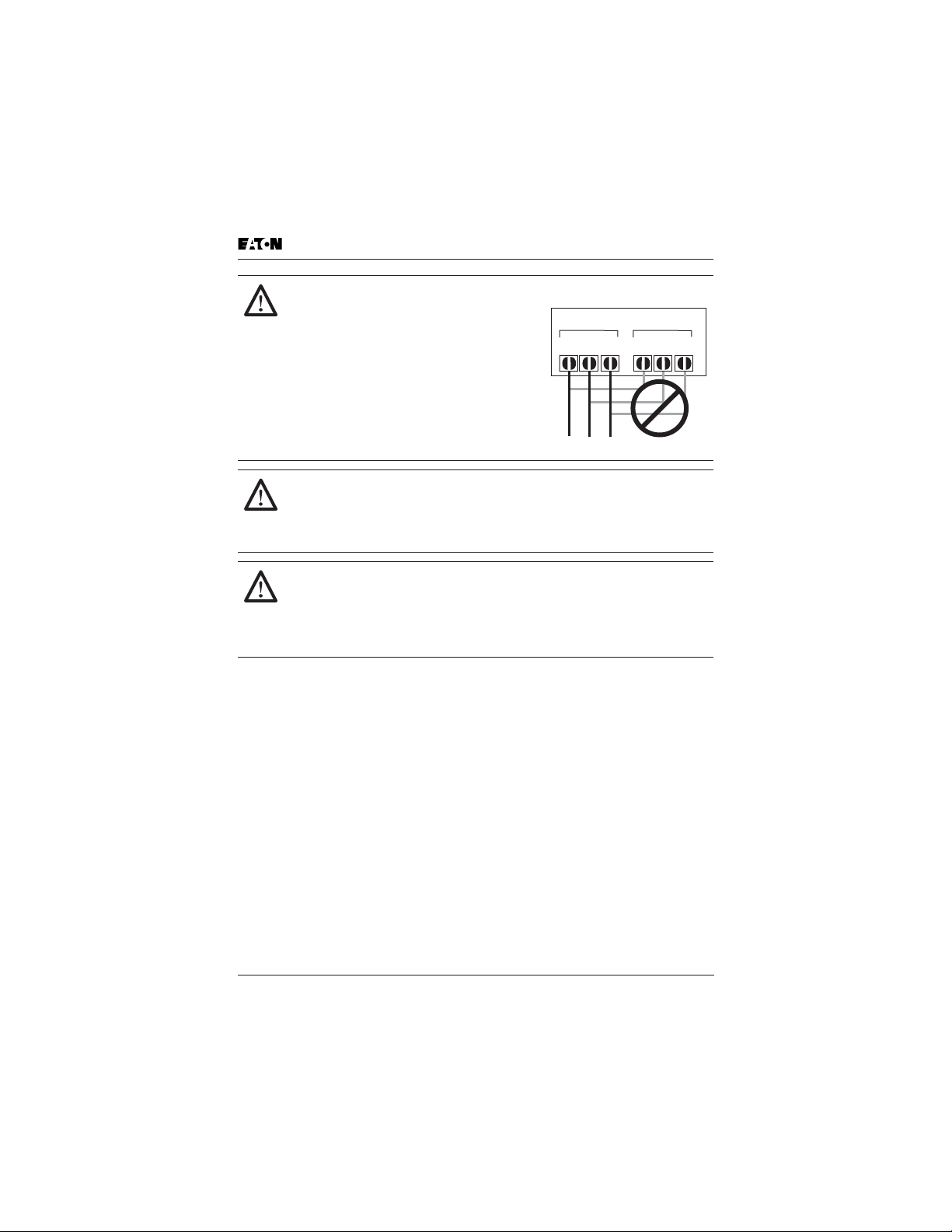
CAUTION!
Be sure not to connect an AC power supply
to the output terminals. Otherwise, there is
the danger of injury and/or fire.
Note:
L1, L2, L3: Three-phase 200 to 230V 50/60 Hz
Three-phase 380 to 460V 50/60 Hz
Three-phase 500 to 600V 50/60 Hz
Any two inputs:
Single-phase 200 to 240V 50/60 Hz
Power Input
L3L2L1
Safety Messages
Power Output
T3
T2T1
CAUTION!
The operation of the inverter can be easily changed from low speed to
high speed. Be sure to check the capability and limitations of the
motor and machine before operating the inverter. Otherwise, there is
the danger of injury.
CAUTION!
If you operate a motor at a frequency higher than the inverter standard
default setting (50 Hz/60 Hz), be sure to check the motor and machine
specifications with the respective manufacturer. Only operate the
motor at elevated frequencies after getting their approval. Otherwise,
there is the danger of equipment damage.
xii GVX9000 User Manual

Chapter 1
Introduction
Inside this chapter …
How to Use This Manual . . . . . . . . . . . . . . . . . . . . . . 1-2
Intended Audience . . . . . . . . . . . . . . . . . . . . . . . . . . . 1-3
Conventions Used in This Manual . . . . . . . . . . . . . . . 1-3
Warranty and Liability Information . . . . . . . . . . . . . . 1-4
Related Publications . . . . . . . . . . . . . . . . . . . . . . . . . . 1-4
Introduction
GVX9000 User Manual 1-1

How to Use This Manual
This chapter describes the purpose and contents of this manual and the intended
audience. This chapter also explains conventions used in this manual and lists
related publications.
How to Use This Manual
Introduction
The purpose of this manual is to provide you with information necessary to
install, set parameters, troubleshoot and maintain the Eaton GVX9000 Adjustable
Frequency Drives from Eaton’s electrical business. To guarantee safe operation of
the equipment, read the safety guidelines at the beginning of this manual before
connecting power to the AC motor drives. Keep this operating manual handy and
distribute to all users for reference.
Chapter 1 — Introduction is the chapter you are reading now.
Chapter 2 — Overview of the GVX9000 Drive describes receiving and inspection
procedures and provides an introduction to digital keypad operation.
Chapter 3 — Storage and Installation describes planning for drive installation
and drive mounting. This chapter also includes requirements and connections for
wiring.
Chapter 4 — Start-Up Procedures provides a detailed explanation of digital
keypad operation.
Chapter 5 — Descriptions of Parameter Settings provides detailed explanations
for all parameter settings.
Chapter 6 — Maintenance and Inspection describes maintenance procedures.
Chapter 7 — Troubleshooting and Fault Information lists the fault displays,
descriptions, and corrective actions.
Appendix A — Technical Data lists standard specifications.
Appendix B — Parameter Tables provides listing of all parameters with
descriptions, ranges and defaults.
Appendix C — Accessories provides information about circuit breakers, fuses,
braking resistors, and other accessories for the Eaton GVX9000 Drives.
Appendix D — Dimensions displays keypad and drive dimensions.
Appendix E
— is a Declaration of Conformity.
1-2 GVX9000 User Manual

Intended Audience
Intended Audience
The audience for this manual has:
•
Knowledge of standard electrical wiring practices, electronic components,
and electrical schematic symbols.
The audience for this manual will install, start-up, and service the Eaton GVX9000
Drives.
Conventions Used in This Manual
Listed below are terms and language conventions used in this manual. These
terms and conventions are defined here to help you understand their meanings
and applications throughout this manual.
Digital Keypad Display
The Digital Keypad display is an LCD readout of drive parameter selections and
drive operation status. Letters or numbers appear in the display according to
which keys you press.
Digital Keypad Keys
Digital Keypad keys are flat, labeled, pushbutton-type devices that allow you to
select drive parameters, and monitor drive operation.
Parameter
A parameter is selected through the Digital Keypad. Parameters in this manual
are expressed as Parameter Group Number, a decimal (.), and a Parameter
number.
Press
Press a key on the Digital Keypad Control Panel to select a parameter. Refer to
Chapter 2 — Overview of the GVX9000 Drive, Digital Keypad Operation.
Introduction
GVX9000 User Manual 1-3

Warranty and Liability Information
Warranty and Liability Information
Eaton Electrical Inc. warrants the product delivered in the Cutler-Hammer
shipping package to be free from defects in material and workmanship, under
normal use and service, for twenty four (24) months from date of manufacturing.
Products that fail during this period will be repaired or replaced at Eaton’s
Introduction
discretion, with the same or a functionally equivalent product, provided the
original purchaser (A) returns the failed product, and (B) provides proof of
original date of purchase. This warranty does not apply, in the judgment of
Eaton, to damage caused during shipment, handling, storage, or accidental
misuse. The original purchaser of the product must obtain a Cutler-Hammer
Return Material Authorization (RMA) number prior to returning any defective
product. (When purchased through an Authorized Distributor, the Distributor
should supply an RMA number to their customer.)
The maximum liability of this warranty is limited to the purchase price of the
product. In no event, regardless of cause, shall Eaton Electrical Inc. be liable (a)
for penalties or penalty clauses of any description, or (b) for certification not
otherwise specifically provided herein and/or indemnification of purchaser or
others for costs, damages or expenses, each arising out of or related to the
product or services of any order or (c) for any damages resulting from loss of
profits, use of products or for any incidental indirect or consequential damages,
even if advised of the possibility of such damages.
Related Publications
Brochure (Publication Numbers: BR04002001E)
Technical Document (Publication Numbers: TD04002001E)
Manual (Publication Number: TD04002003E)
Contact Name, Number:
Eaton Electrical Inc.
1000 Cherrington Parkway
Moon Township, PA 15108-4312
Tel: 1-800-525-2000
www.EatonElectrical.com
1-4 GVX9000 User Manual

Chapter 2
Overview of the GVX9000 Drive
Inside this chapter …
Receiving and Inspection . . . . . . . . . . . . . . . . . . . . . . 2-2
Nameplate Information . . . . . . . . . . . . . . . . . . . . . 2-2
Catalog Number . . . . . . . . . . . . . . . . . . . . . . . . . . 2-3
Style Number . . . . . . . . . . . . . . . . . . . . . . . . . . . . . 2-4
External Parts and Label Locations . . . . . . . . . . . . . . 2-4
Digital Keypad Operation . . . . . . . . . . . . . . . . . . . . . . 2-5
Overview of the
GVX9000 Drive
GVX9000 User Manual 2-1
Receiving and Inspection
Receiving and Inspection
This GVX9000 AC drive has gone through quality control tests at the factory before
shipment. After receiving the AC motor drive, please check for the following:
•
Check to make sure that the package includes an AC drive and User Manual.
•
Inspect the unit to insure it was not damaged during shipment.
•
Make sure that the part number indicated on the nameplate corresponds with
the part number of your order.
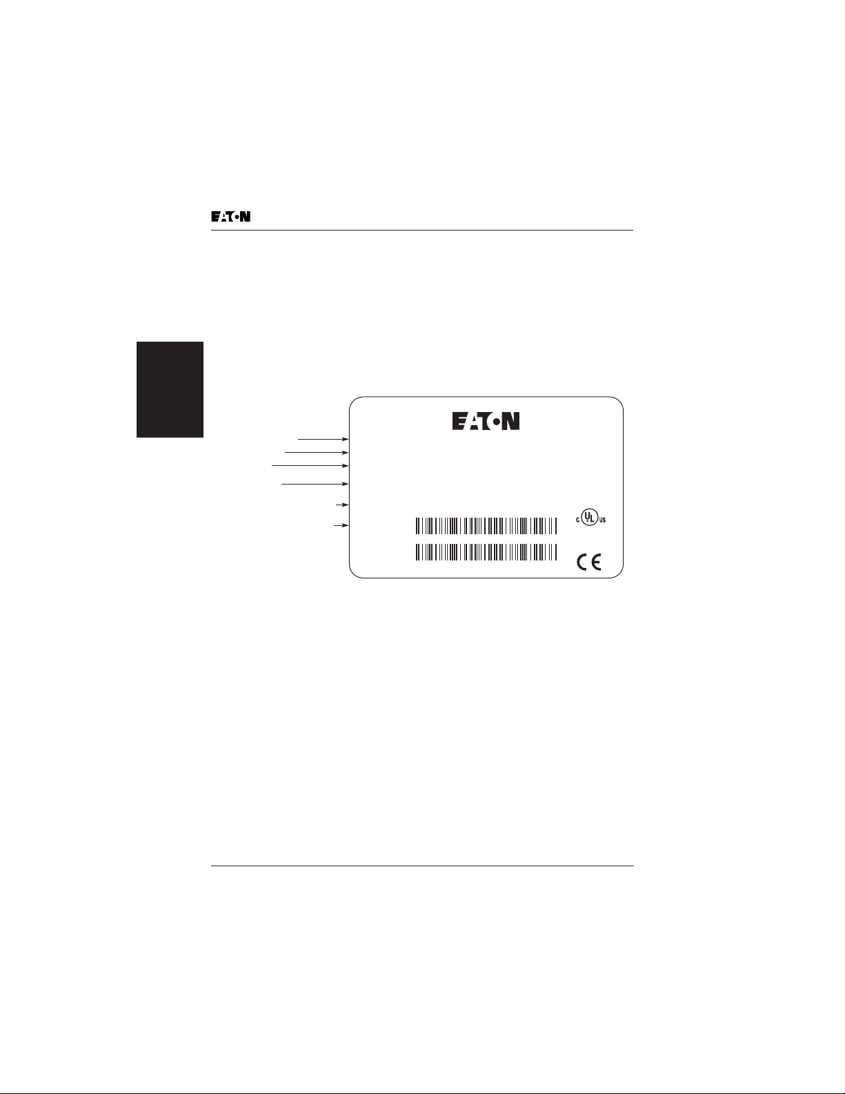
Nameplate Information
GVX9000 Drive
Overview of the
Catalog Number
Style Number
Input Spec.
Output Spec.
Output Frequency Range
Serial Number Bar Code
Cat. No. :
Style No. :
Input :
Output :
GVX005A1-2
200-240Vac, 50-60Hz, 3ph, 20.6A
CT: 0-240Vac, 3PH, 17A, 5HP
VT: 0-240Vac, 3PH, 17A, 5HP
Frequency Range : 0.1-400Hz Output
7 82116 97861 8
MADE IN XXXXXX
G005A120T6160001
Figure 2-1: Example of 5 hp 230V AC drive
LISTED
Ind. Cont. Eq.
19XK
2-2 GVX9000 User Manual
Receiving and Inspection
Catalog Number
Table 2-1: GVX9000 Catalog Numbering System
G V X 0 0 1 A1 -2
Model Number
Motor Horsepower
001 = 1 hp (0.7 kW)
002 = 2 hp (1.5 kW)
003 = 3 hp (2.2 kW)
005 = 5 hp (3.7 kW)
007 = 7-1/2 hp (5.5 kW)
010 = 10 hp (7.5 kW)
015 = 15 hp (11 kW)
020 = 20 hp (15 kW)
025 = 25 hp (18.5 kW)
030 = 30 hp (22 kW)
040 = 40 hp (30 kW)
050 = 50 hp (37 kW)
060 = 60 hp (45 kW)
075 = 75 hp (55 kW)
100 = 100 hp (75 kW)
2 = 230V AC
4 = 460V AC
5 = 575V AC
Enclosure
Version Type
Voltage
Overview of the
GVX9000 Drive
GVX9000 User Manual 2-3
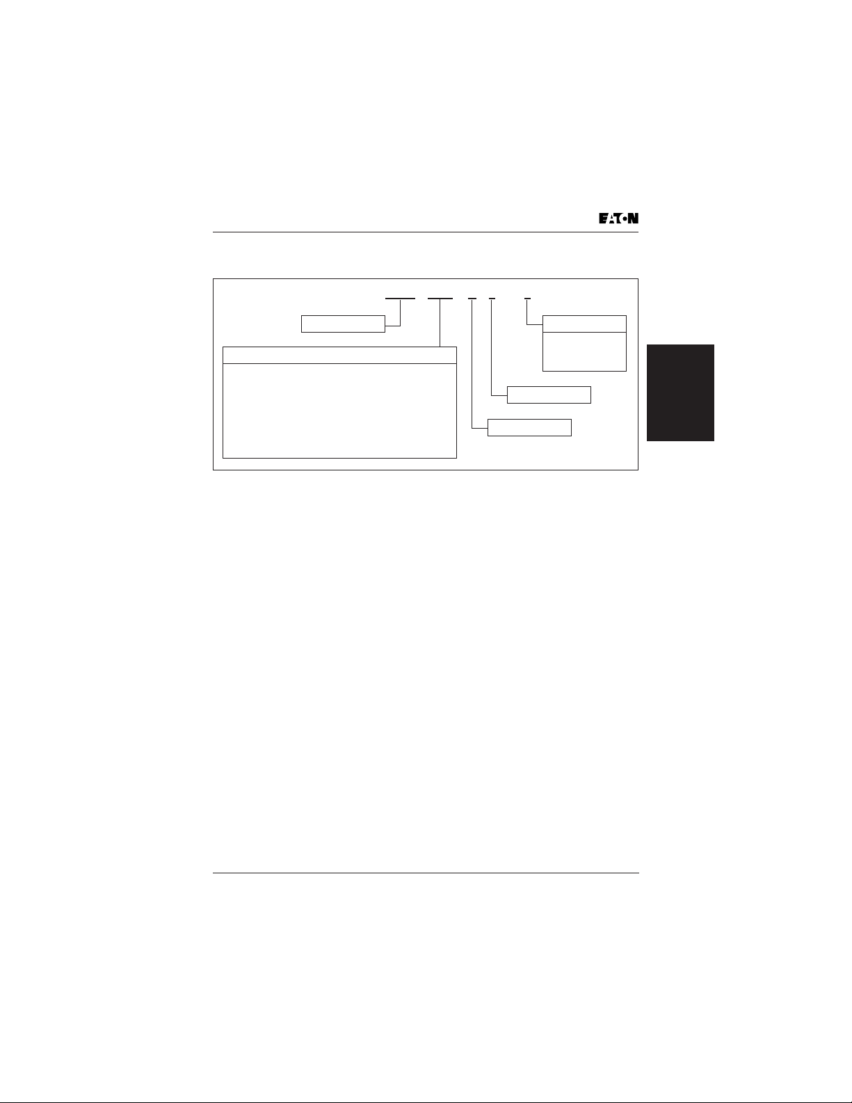
External Parts and Label Locations
Style Number
The style number contains the same information as the Catalog Number, and is
used internally for ordering purposes.
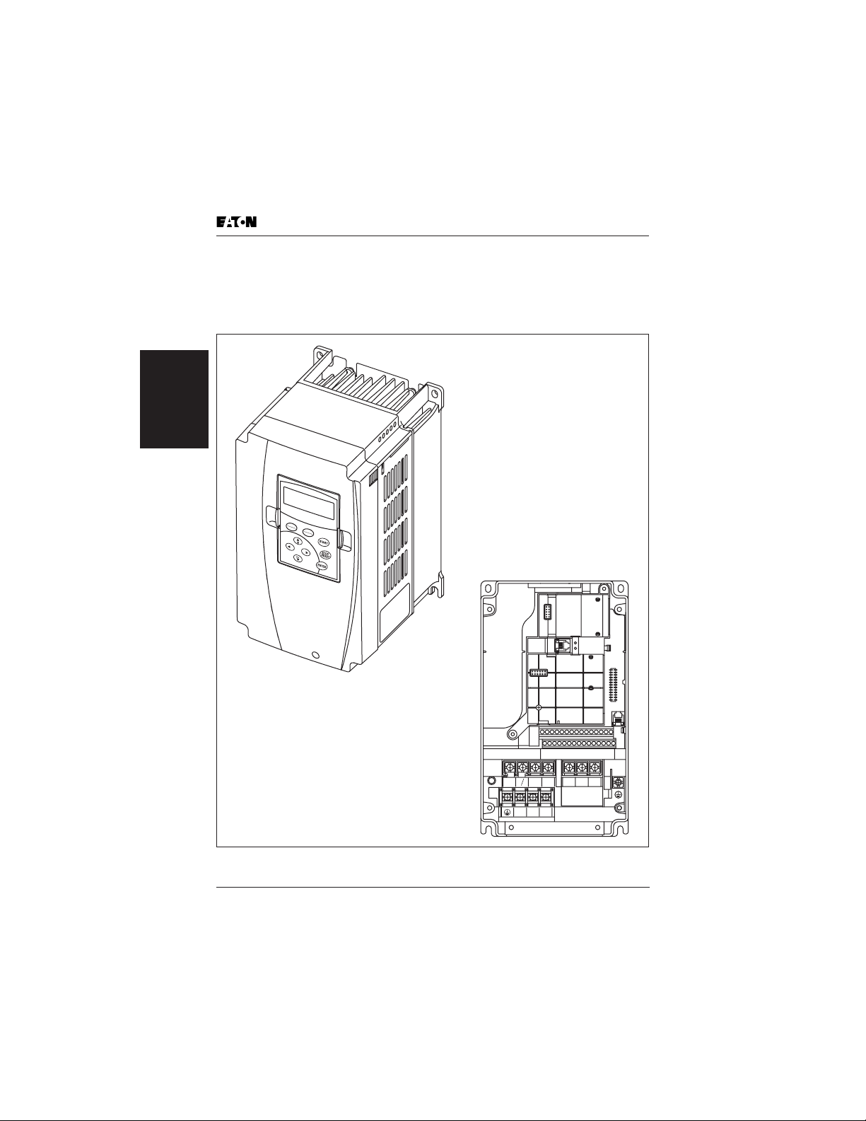
External Parts and Label Locations
GVX9000 Drive
Overview of the
RUN
STOP
FWD
REV
LO
FWD
C
REV
LOC
REM
+2
R/L1+1S/L2 T/L3
U/T1 V/T2 W/T3
-
2
B
B
1
Screw Torque :
18Kgf-cm
Wire Gauge :
18~10AWG
Figure 2-2: Parts and Label
2-4 GVX9000 User Manual
Digital Keypad Operation
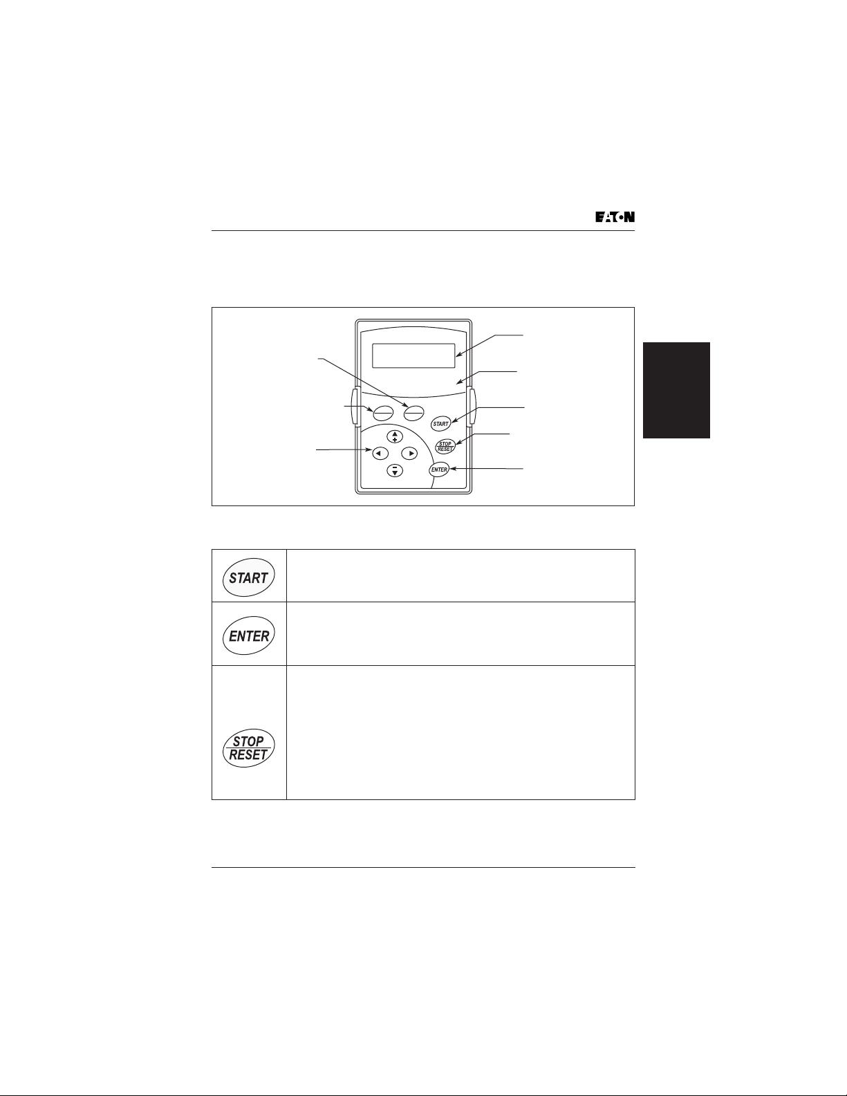
Digital Keypad Operation
The digital keypad includes the display panel and the keypad. The display panel
provides the parameter display and shows the operation status of the AC drive.
The keypad provides programming and control interface.
LCD Display
Indicates Motor and
LOC REM Key
Switches the Control
from Local Control Source
to Remote Control Source
FORWARD REVERSE Key
Up, Down and
Right/Left Keys
Scrolls Display,
Enter/Exit Parameter Mode,
Change Parameter Settings
Figure 2-3: Description of Digital Keypad
Table 2-2: Keypad Operators
START
This button operates as Start button for normal operation
• Motor START from the panel; active control place has to be
selected at “Panel”
ENTER
This button in the parameter edit mode is used to enter the
programming mode and enter the parameter selection.
• used for parameter edit confirmation, acceptance (confirmation)
of the edited parameter value with exit from parameter edit mode
STOP / RESET
This button has two integrated operations. The button operates as
Stop button for normal operation. In the parameter edit mode it is
used to cancel previous action and back-up one step, and in fault
mode it is used to reset the fault.
STOP
• motor STOP from the panel; active control place has to be
selected at “Panel”
RESET
• used to reset an Active Fault on the drive and shown in the
display
RUN STOP FWD REV LOC
LOC
FWD
REM
REV
Drive Parameter
LED Indicators
Lamp Lights During Run,
Stop, Fwd, Rev, Loc Operations
START Key
Start Command
STOP/RESET Key
Stop Command and Reset
the Drive After a Fault Occurs
ENTER Key
Used in Parameter Mode
to Enter and Change Values
Overview of the
GVX9000 Drive
GVX9000 User Manual 2-5
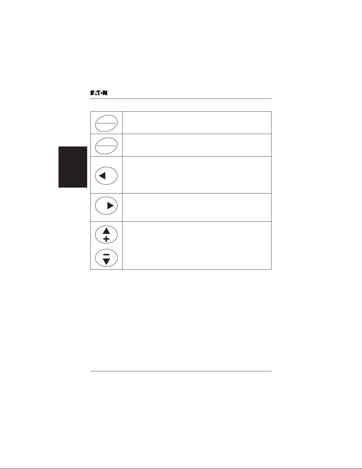
Table 2-2. Keypad Operators (Continued)
This button switches the Control Location from the Local Source to
LOC
the Remote Source.
REM
This button changes the direction of the motor connected to the
FWD
GVX9000 drive.
REV
LEFT Arrow
• navigation button, movement to left
• in display mode, enter parameter group mode
GVX9000 Drive
Overview of the
• in parameter edit mode, exits mode, backs up one step
• cancels edited parameter (exit from a parameter edit mode)
RIGHT Arrow
• navigation button, movement to right
• enter parameter group mode
• enter parameter mode from group mode
• Changes the cursor location when entering data into a parameter
UP and DOWN Arrows
• move either up or down the group list in order to select the
desired group menu.
• move either up or down the parameter list in order to select the
desired parameter in the group.
• increasing/decreasing of reference value on the keyboard (when
selected).
Digital Keypad Operation
2-6 GVX9000 User Manual

Chapter 3
Storage and Installation
Inside this chapter …
Storage . . . . . . . . . . . . . . . . . . . . . . . . . . . . . . . . . . . . 3-2
Environment . . . . . . . . . . . . . . . . . . . . . . . . . . . . . . . . 3-2
Operation . . . . . . . . . . . . . . . . . . . . . . . . . . . . . . . . 3-2
Storage . . . . . . . . . . . . . . . . . . . . . . . . . . . . . . . . . . 3-2
Transportation . . . . . . . . . . . . . . . . . . . . . . . . . . . . 3-2
Pollution Degree . . . . . . . . . . . . . . . . . . . . . . . . . . 3-2
Mounting Area . . . . . . . . . . . . . . . . . . . . . . . . . . . . . . 3-3
Wiring . . . . . . . . . . . . . . . . . . . . . . . . . . . . . . . . . . . . . 3-4
Applicable Codes . . . . . . . . . . . . . . . . . . . . . . . . . . . . 3-4
Basic Wiring Diagram . . . . . . . . . . . . . . . . . . . . . . . . . 3-5
External Wiring . . . . . . . . . . . . . . . . . . . . . . . . . . . . . . 3-8
Control Terminal Wiring (Factory Settings) . . . . . . . . 3-10
Main Circuit Wiring . . . . . . . . . . . . . . . . . . . . . . . . . . . 3-11
Wiring Notes . . . . . . . . . . . . . . . . . . . . . . . . . . . . . . . . 3-17
Motor Operation Precautions . . . . . . . . . . . . . . . . . . 3-18
Storage and
Installation
GVX9000 User Manual 3-1

Storage
The AC drive should be stored in the shipping carton before installation. In order
to retain the warranty coverage, the AC drive should be stored properly when it is
not to be used for an extended period of time. Some storage suggestions are:
• Store in a clean and dry location free from direct sunlight or corrosive fumes.
• Store within an ambient temperature range of -20 to +60°C.
• Store within a relative humidity range of 0 to 90% and non-condensing
environment.
• Store within an air pressure range of 86 to 106 kPA.
Environment
Operation
Air Temperature: 1 hp – 100 hp -10 to +50°C (14 to 122°F)
Relative Humidity: 0% to 90%, no condensation allowed
Atmosphere Pressure: 86 to 106 kPa
Installation Site Altitude: below 1000m
Vibration: Maximum 9.80 m/s2 (1G) at less than 20 Hz
Installation
Storage and
Storage
Temperature: -20 to +60°C (-4 to 140°F)
Relative Humidity: Less than 90%, no condensation allowed
Atmosphere Pressure: 86 to 106 kPa
Maximum 5.88 m/s2 (0.6G) at 20 to 50 Hz
Storage
Transportation
Temperature: -20 to +60°C (-4 to 140°F)
Relative Humidity: Less than 90%, no condensation allowed
Atmosphere Pressure: 86 to 106 kPa
Vibration: Maximum 9.80 m/s2 (1G) at less than 20 Hz,
Maximum 5.88 m/s2 (0.6G) at 20 to 50 Hz
Pollution Degree
UL Type 0, Pollution Degree 2: good for a factory type environment
Relative Humidity: Less than 90%, no condensation allowed
Atmosphere Pressure: 86 to 106 kPa
3-2 GVX9000 User Manual
Mounting Area
Mounting Area
Improper installation of the AC drive will greatly reduce its life. Be sure to
observe the following precautions when selecting a mounting location. Failure to
observe these precautions may void the warranty!
Do not mount the AC drive near heat-radiating elements or in direct sunlight.
Do not install the AC drive in a place subjected to high temperature, high
humidity, excessive vibration, corrosive gases or liquids, or airborne dust or
metallic particles.
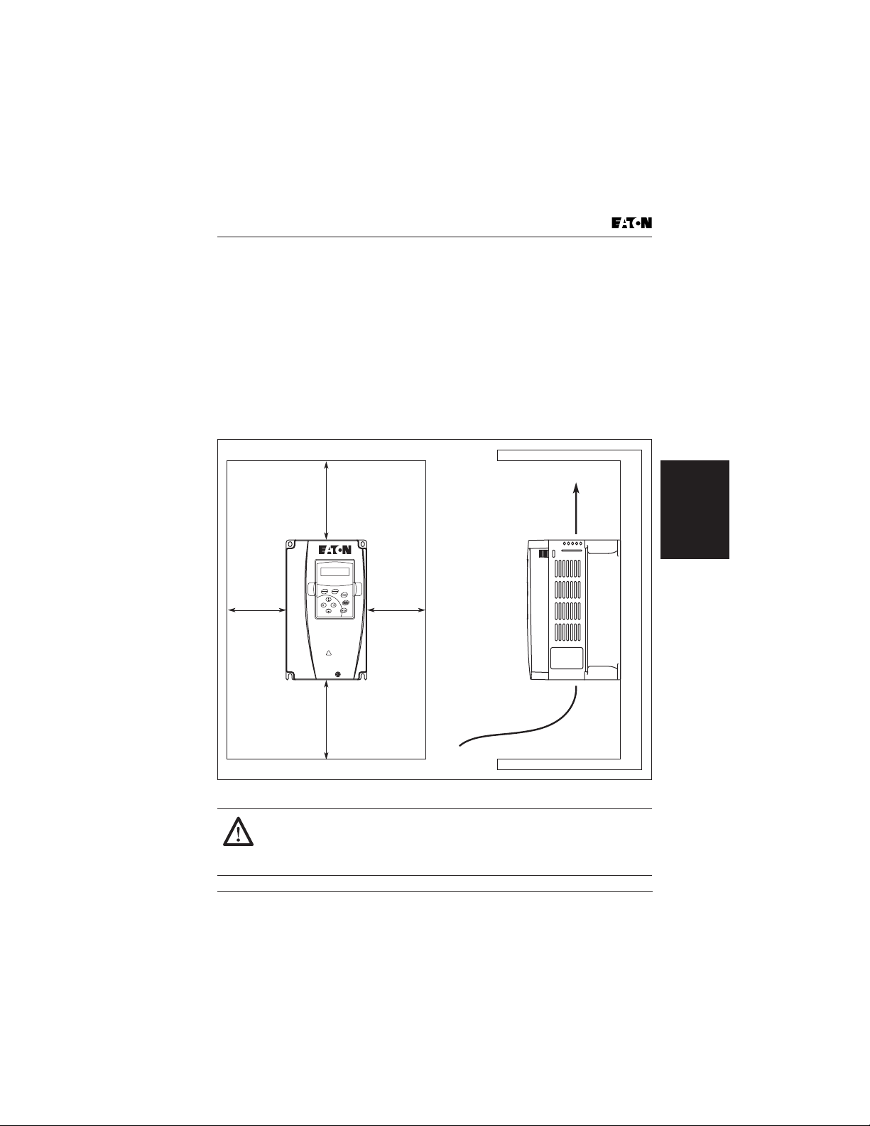
Mount the AC drive vertically and do not restrict the air flow to the heatsink fins.
The AC drive generates heat. Allow sufficient space around the unit for heat
dissipation as shown in Figure 3-1.
2.0 (50)
or More
5.9 (150)
or More
RUN STOP FWD REV LOC
LOC
FWD
REM
REV
GVX9000
Sensorless Vector
!
WARNING
HIGH VOLTAGE!
WAIT AT LEASTS 10 MINUTES BEFORE OPENING.
SEE USER’S MANUAL FOR OPERATION.
2.0 (50)
or More
Air Flow
Storage and
Installation
5.9 (150)
or More
Figure 3-1: Mounting in an Enclosure in Inches (mm)
CAUTION!
When mounting in an enclosure, allow for the recommended free
space. Failure to allow adequate air flow may result in drive over
temperature.
GVX9000 User Manual 3-3

Wiring
HIGH VOLTAGE!
Before opening the AC drive covers:
• Disconnect all power to the AC drive.
Wait five minutes for DC bus capacitors discharge.
Any electrical or mechanical modification to this equipment without prior
written consent of Eaton will void all warranties and may result in a safety
hazard in addition to voiding the UL listing.
Short Circuit Withstand: The rated voltage for AC motor drive must be equal or
less than 240V (equal or less than 480V for 460V models, equal or less than 600V
for 575V models) and the mains supply current capacity must be equal or less
than 5000A RMS (equal or less than 10000A RMS for the 40 hp [30 kW] models).
Applicable Codes
All Eaton GVX9000 AC drives are Underwriters Laboratories, Inc. (UL) and Canadian
Underwriters Laboratories (cUL) listed, and therefore comply with the requirements
of the National Electrical Code (NEC) and the Canadian Electrical Code (CEC).
Installation intended to meet the UL and cUL requirements must follow the
instructions provided in “Wiring Notes” as a minimum standard. Follow all local
Installation
Storage and
codes that exceed UL and cUL requirements. Refer to the technical data label
affixed to the AC drive and the motor nameplate for electrical data.
The “Line Fuse Specification” in Appendix C lists the recommended fuse part
number for each GVX9000 part number. These fuses (or equivalent) must be
used on all installations where compliance with UL standards is required.
According to the Low Voltage Directive 73/23/EEC and the Amendment Directive
93/68/EEC Digital Keypad, the following AC Motor Drives, GVX001A1-2, GVX002A1-2,
GVX003A1-2, GVX005A1-2, GVX007A1-2, GVX010A1-2, GVX015A1-2, GVX020A1-2,
GVX025A1-2, GVX030A1-2, GVX040A1-2, GVX050A1-2, GVX001A1-4, GVX002A1-4,
GVX003A1-4, GVX005A1-4, GVX007A1-4, GVX010A1-4, GVX015A1-4, GVX020A1-4,
GVX025A1-4, GVX030A1-4, GVX040A1-4, GVX050A1-4, GVX060A1-4, GVX075A1-4,
GVX100A1-4, are herewith confirmed to comply with the requirements set out in the
Council Directive 73/23/EEC for electrical equipment used within certain voltage limits
and the Amendment Directive 93/68/EEC. For the evaluation of the compliance with
this Directive, the following standard was applied: EN 50178.
According to the Electromagnetic Compatibility 89/336/EEC and the Amendment
Directive 93/68/EEC, the following equipment, AC Motor Drive, GVX001A1-2,
GVX002A1-2, GVX003A1-2, GVX005A1-2, GVX007A1-2, GVX010A1-2, GVX015A1-2,
GVX020A1-2, GVX025A1-2, GVX030A1-2, GVX040A1-2, GVX050A1-2, GVX001A1-4,
GVX002A1-4, GVX003A1-4, GVX005A1-4, GVX007A1-4, GVX010A1-4, GVX015A1-4,
GVX020A1-4, GVX025A1-4, GVX030A1-4, GVX040A1-4, GVX050A1-4, GVX060A1-4,
GVX075A1-4, GVX100A1-4, is herewith confirmed to comply with the requirements set
out in the Council Directive 89/336/EEC for electromagnetic compatibility and the
Amendment Directive 93/68/EEC. For the evaluation of the compliance with this
Directive, the following standards were applied: EN61800-3, EN55011, EN50081-2,
EN50082-2, EN61000-4-2, EN61000-4-3, EN61000-4-4, EN61000-4-5, EN61000-4-6,
EN61000-4-8.
Wiring
3-4 GVX9000 User Manual
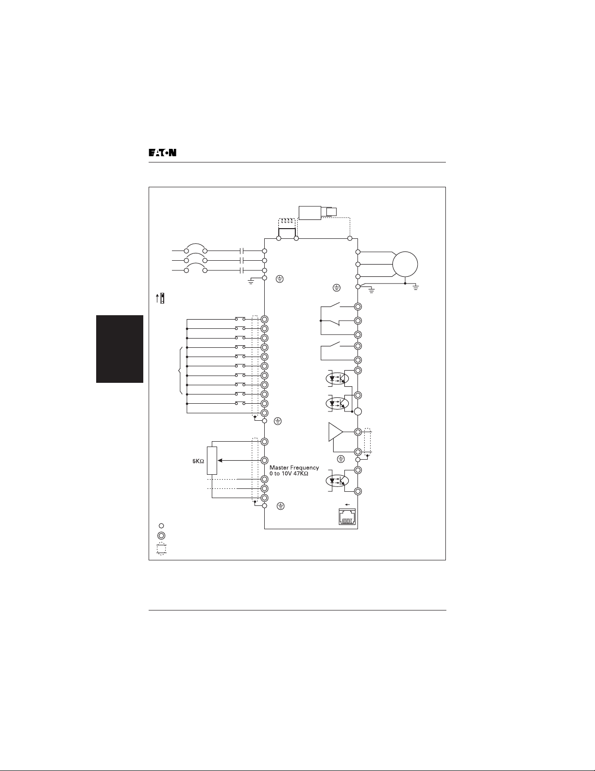
Basic Wiring Diagram
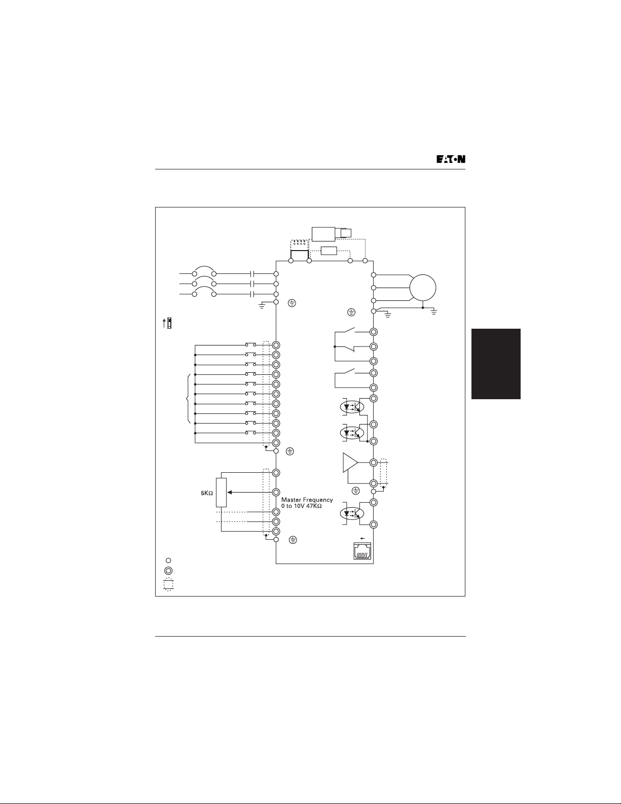
Basic Wiring Diagram
For Models of GVX9000 Series —
1 to 5 horsepower
Refer to Appendix for the use of Special Braking Resistor/Unit
Fuse/NFB
(None Fuse Breaker)
R(L1)
S(L2)
T(L3)
Factory Setting: SINK Mode
Sink
Refer to Figure 3-4 for
wiring of SINK Mode
Sw1
and SOURCE Mode.
Source
Factory
Setting
* Donít apply the mai ns voltage
directly to above terminals.
RUN/STOP
REV/FWD
Multi-Step 1
Multi-Step 2
Multi-Step 3
Multi-Step 4
Reset
E.F.
Digital Signal Common
3
2
1
4~20mA
-10~+10V
Analog Signal Common
Main Circuit (Power) Terminals
Control Circuit Terminals
Shielded Leads & Cable
Figure 3-2: Wiring Diagram — 1 – 5 hp
Braking Resistor/Unit (Optional)
BR
DC Chock
(Optional)
Jumper
R(L1)
S(L2)
T(L3)
E
+24V
D1
D2
D3
D4
D5
D6
D7
D8
D9
D10
COM
E
+10V
Power Supply
+10V 20mA
AI1
AI2
AI3
AE
* Three-phase input power may apply to single-phase drives.
* For the single-phase drives, the AC input line can be
connected to any two of the three input terminals R, S, T.
GBM
BR
B2
DO1
DO2
(minus sign)
DPO
-
U(T1)
V(T2)
W(T3)
E
RA1
RA3
Factory Setting:
Drive Running
RA2
RB1
Factory Setting:
Fault Indication
RB2
48V50mA
Factory Setting:
Warning
Factory Setting: Freq.
Setting I
48V50mA
Digital Output
Common
DOC
AO+
A-
E
Digital Frequency
Output Terminal
Factory Setting: 1:1
Duty=50%
Digital Signal Common
COM
6 1
RS-485
Serial Interface
3: SG4: SG+
Analog Multi-Function
Output Terminal
Factory Default: Analog
Freq./Current Meter
0~10VDC/2mA
Analog Signal Common
+2/B1
+1
Motor
IM
3~
ndication
Storage and
Installation
GVX9000 User Manual 3-5
Basic Wiring Diagram
For Models of GVX9000 Series —
Refer to Appendix for the use of Special Braking Resistor/Unit
Fuse/NFB
(None Fuse Breaker)
R(L1)
S(L2)
T(L3)
Factory Setting: SINK Mode
Sink
Refer to Figure 3-4 for
wiring of SINK Mode
Sw1
and SOURCE Mode.
Source
Installation
Storage and
Factory
Setting
* Don’t apply the mains voltage
directly to above terminals.
RUN/STOP
REV/FWD
Multi-Step 1
Multi-Step 2
Multi-Step 3
Multi-Step 4
Reset
E.F.
Digital Signal Common
3
2
1
4~20mA
-10~+10V
Analog Signal Common
Main Circuit (Power) Terminals
Control Circuit Terminals
Shielded Leads & Cable
Figure 3-3: Wiring Diagram — 7-1/2 – 100 hp
7-1/2 to 100 horsepower
Braking Resistor/Unit (Optional)
BR
DC Chock
(Optional)
Jumper
R(L1)
S(L2)
T(L3)
E
+24V
D1
D2
D3
D4
D5
D6
D7
D8
D9
D10
COM
E
+10V
Power Supply
+10V 20mA
AI1
AI2
AI3
AE
* Three-phase input power may apply to single-phase drives.
* For the single-phase drives, the AC input line can be
connected to any two of the three input terminals R, S, T.
GBM
DO1
DO2
(minus sign)
DPO
-
U(T1)
V(T2)
W(T3)
E
RA1
RA3
Factory Setting:
Drive Running
RA2
RB1
Factory Setting:
Fault Indication
RB2
48V50mA
Factory Setting:
Warning
Factory Setting: Freq.
Setting In
48V50mA
Digital Output
Common
DOC
AO+
A-
E
Digital Frequency
Output Terminal
Factory Setting: 1:1
Duty=50%
Digital Signal Common
COM
6 1
RS-485
Serial Interface
3: SG4: SG+
Analog Multi-Function
Output Terminal
Factory Default: Analog
Freq./Current Meter
0~10VDC/2mA
Analog Signal Common
+2
+1
Motor
IM
3~
dication
3-6 GVX9000 User Manual
 Loading...