

Eaton EAFR-101C User Manual
Instruction Booklet IB0191002EN
Effective November 2019
EAFR-101C arc point sensor relay
user manual
Contents
Description Page
1 Introduction ............................2
2 General ................................2
3 Operation and configuration ................4
4 Arc sensors ............................7
5 System self-supervision ...................8
6 Application examples .....................9
7 Connections ............................9
8 Dimensions and installation ...............11
9 Testing ...............................12
10 Troubleshooting guide ...................14
11 Technical data .........................14
12 Ordering codes .......................16
Instruction Booklet IB0191002EN
Effective November 2019
EAFR-101C arc point sensor relay
user manual
CAUTION
ELECTRICAL EQUIPMENT SHOULD BE INSTALLED, OPERATED, SERVICED,
AND MAINTAINED ONLY BY QUALIFIED PERSONNEL. LOCAL SAFETY
REGULATIONS SHOULD BE FOLLOWED.
NO RESPONSIBILITY IS ASSUMED BY EATON FOR ANY CONSEQUENCES
ARISING OUT OF THE USE OF THIS MATERIAL.
1 Introduction
Read these instructions carefully and inspect the equipment to
become familiar with it before trying to install, operate, service, or
maintain it.
Electrical equipment should be installed, operated, serviced, and
maintained only by qualified personnel. Local safety regulations
should be followed. No responsibility is assumed by Eaton for any
consequences arising out of the use of this material.
Eaton reserves right to changes without further notice.
1.1 Abbreviations
CB – Circuit breaker
CBFP – Circuit breaker failure protection
EMC – Electromagnetic compatibility
EPROM – Erasable programmable read only memory
HW – Hardware
LED – Light emitting diode
LV – Low voltage
ms – Millisecond
MV – Medium voltage
NC – Normally closed
NO – Normally open
PMSG – Permanent magnet synchronous generator
Rx – Receiver
SF – System failure
SW – Software
Tx – Transceiver
uP – Microprocessor
2 General
The Eaton arc flash relay 101C (EAFR-101C) is a sophisticated
micro-processor based arc flash protection relay including complete
self-supervision functionality. It is designed to minimize the damage
caused by an arcing fault (arc flash) by sensing light from the point
sensor and acting to trip the circuit breaker sourcing the fault
current. The EAFR-101C complete system self-supervision function
provides the highest level of dependability by continuously monitoring all internal system functions along with external connections.
The EAFR-101C is designed according to the latest protection relay
standards and is therefore suitable for installations in rough environments, such as utility, traditional or renewable power plants, off
shore, marine, oil and gas, mining, steel, or any other heavy industry
applications. It is also well suited for commercial and institutional
electrical systems. The EAFR-101C is suitable for either medium
voltage or low voltage switchgear and motor control center applications in both new and retrofit installations.
2.1 EAFR-101C features
The EAFR-101C is a multipurpose arc flash protection relay that can
receive light from four different channels of light point sensors and
can be applied for variety of applications. The EAFR-101C can be
used as a stand-alone relay or as part of a more complex arc protection system through the binary bus.
Main features of EAFR-101C:
•
(110-220) Vac / (125-250) Vdc auxiliary power supply;
•
(18-72) Vdc optional power supply;
•
Four arc point sensor channels (S1, S2, S3, and S4);
•
Six binary inputs (BI1, BI2, BI3, BI4, BI5, and BI6) nominal voltage
of 24 Vdc;
•
Three normally open trip relay outputs with direct trip circuit rated
contacts (T1, T2, and T3);
•
One normally open electronic lock-out trip relay with direct trip
circuit rated contacts (T2);
•
Two 24 Vdc binary outputs (BO1 and BO2);
•
One system failure relay, form C output (SF);
•
16 indication LEDs; and
•
One push-button (SET).
Figure 1. The EAFR-101C arc protection IO relay.
2
EATON www.eaton.com
EAFR-101C arc point sensor relay
user manual
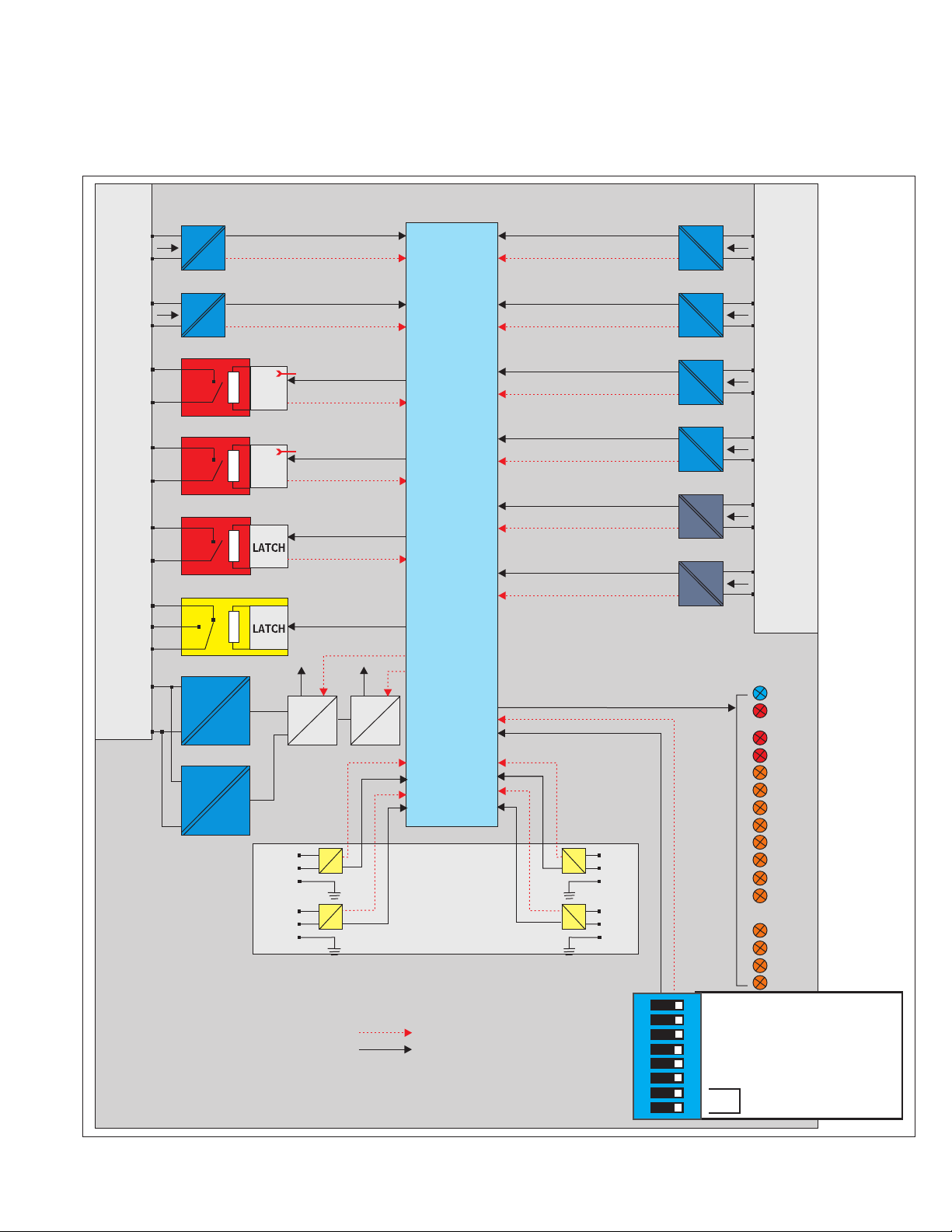
2.2 Simplified block diagram
The EAFR-101C simplified block diagram (see Figure 2) shows the
main components of the EAFR-101C relay.
Instruction Booklet IB0191002EN
Effective November 2019
X2
BI1
BI2
T1
T2
T3
SF
X1
15
14
13
12
EN
11
10
9
8
7
LATCH
LATCH
SW6
EN
SW6
15
14
12
11
10
9
8
7
6
5
BI3
BI4
BI5
BI6
BO1
uP
6
5
4
3
4
3
BO2
Uaux
2
1
125...250
Vdc
24 Vdc
110...220
Vac/dc
24 Vdc
S1
S2
24 Vdc
12 Vdc
12
11
10
9
8
7
12 Vdc
5 Vdc
X3
Self supervision
Control and power supply
6
S3
5
4
3
S4
2
1
ON OFF
Power
Error
T1,T3
T2,T3
BI1
BI2
BI3
BI4
BI5
BI6
BO1
BO2
S1
S2
S3
S4
8
S1/S2 Chan: L/L+C
7
S3/S4 Chan: L/L+C
6
T1/T2: Latch/NL
5
CB1 in use: Yes/no
4
CB2 in use: Yes/no
MT/C
3
2
1
Configuration
select
Figure 2. EAFR-101C simplified block diagram.
EATON www.eaton.com
3

Instruction Booklet IB0191002EN
Effective November 2019
EAFR-101C arc point sensor relay
user manual
3 Operation and conguration
3.1 LED indicator functions
The EAFR-101C contains 16 indication LEDs. A user definable text
pocket can be slid in under the label for identifying each LED function (except POWER and ERROR LEDs). LEDs are located at the
front plate of the relay for clear viewing without a need for opening
doors.
During power up, the relay performs an LED test. All LEDs are
turned on for two seconds and then off. Only the blue POWER LED
will remain on. After powered up, the relay goes into protection
mode in 50 ms even while the LED test is being performed.
During normal operation, the blue power LED is ON, as are any CB
open/close status LED’s for connected CB’s.
The sensor LEDs are off during the inactive condition. If a point arc
sensor is activated, the corresponding sensor channel LED will turn
on if the activation is longer than 1.5 ms. The sensor LED activation
In case of a loose sensor wire and binary input wires or configuration mismatch (new sensor attached without running auto-configuration system setup (see Section 3.3.1) situation, the corresponding
LED for that sensor will start flashing and the ERROR LED will
activate.
The Binary I/O LEDs indicate the I/O-line status. If any of the lines
become active for more than 1.5 ms, the corresponding LED will
turn on (latch).
In a trip situation, the corresponding trip LED will turn on. Trip
outputs are controlled by the dipswitch settings (see Section 3.5).
All activation and trip indication LEDs are latched, even if the
dipswitch setting is in the non-latched mode. They have to be
cleared by pushing the “SET” button.
LED indications are stored in non-volatile EPROM memory for identifying the trip information in case the auxiliary power is lost. When
re-powering the relay after power supply loss, the actual LED status
can be visualized from the front of the relay.
function is latched (steady light). To clear the LED, the “SET” button
should be pressed.
3.2 LED operation quick guide
Table 1. LED operation quick guide.
LED Off Steady On Blinking Action if Abnormal
POWER - Blue Auxiliary supply
disconnected.
ERROR - Red System healthy. System failure. Configuration mismatch.
T1, and T3 - Red Normal status. Trip relays T1 and T3 activated. N/A Check the reason for trip. Clear the fault
T2, and T3 - Red Normal status. Trip relays T2 and T3 activated. N/A Check the reason for trip. Clear the fault
BI1 - Amber CB open. CB closed. Loose connection/dipswitch
BI2 - Amber CB closed. CB open. Loose connection/dipswitch
BI3 - Amber CB open. CB cLosed. Loose connection/dipswitch
BI4 - Amber CB closed. CB open. Loose connection/dipswitch
BI5 - Amber Normal status. Current/MT indication. Binary input 5 has loose
BI6 - Amber Normal status. Blocking signal input.. Binary input 6 has loose
BO1 - Amber Normal status. Light > output. N/A N/A
BO2 - Amber Normal status. Blocking signal high. N/A N/A
S1 - Amber Normal status. Sensor channel 1 activated by
S2 - Amber Normal status. Sensor channel 2 activated by
S3 - Amber Normal status. Sensor channel 3 activated by
S4 - Amber Normal status. Sensor channel 4 activated by
Auxiliary power connected. N/A Check the power source.
Verify system condition. See Sections
11: Troubleshooting guide and 5: System
self-super vision.
and reset indications by pushing SET
button.
and reset indications by pushing SET
button.
Check the binary input wiring/dipswitch
setting.
Check the binary input wiring/dipswitch
setting.
Check the binary input wiring/dipswitch
setting.
Check the binary input wiring/dipswitch
setting.
Check the binary input wiring.
Check the binary input wiring.
Check why the sensor activated, check
the sensor wire connection, or perform
the system set-up (see Section 3.3.1:
Auto-configuration (System setup).
Check why the sensor activated, check
the sensor wire connection, or perform
system set-up (see Section 3.3.1: Autoconfiguration (System setup).
Check why the sensor activated, check
the sensor wire connection, or perform
system set-up (see Section 3.3.1: Autoconfiguration (System setup).
Check why the sensor activated, check
the sensor wire connection, or perform
system set-up (see Section 3.3.1: Autoconfiguration (System setup).
light information
light information.
light information.
light information
Protection partly operational.
mismatch.
mismatch.
mismatch.
mismatch.
connection.
connection.
Sensor channel 1 has loose
connection or the system setup was not performed. Also
activated by pressure information
(if L+P sensors used).
Sensor channel 2 has loose
connection or system set-up
not performed. Also activated
by pressure information (if L+P
sensors used).
Sensor channel 3 has loose
connection or system set-up
not performed. Also activated
by pressure information (if L+P
sensors used).
Sensor channel 4 has loose
connection or system set-up
not performed. Also activated
by pressure information (if L+P
sensors used).
4
EATON www.eaton.com

EAFR-101C arc point sensor relay
user manual
Instruction Booklet IB0191002EN
Effective November 2019
3.3 Push-button description
The EAFR-101C contains one single push-button (SET) that can be
used for all operational functions of the relay. The push-button is
used to initialize the auto-configuration of the system (see Section
3.3.1) and for resetting the indicators and latched output relays.
3.3.1 Auto configuration (System setup)
When all sensors and binary lines have been connected, an
auto-configuration procedure must be executed. The initialization sequence is performed by pressing the “Set” button for two
seconds. The EAFR-101C sensor LEDs and all binary LEDs start
blinking. The relay scans these inputs to see if they are connected
and when an input is detected, the corresponding LEDs are illuminated to mark that a connection was found. The inputs without
connection continue blinking during the remaining three seconds.
After five seconds, all LEDs are turned off. During this system
setup, the dipswitch setting are also stored in non-volatile memory.
All sensor inputs will remain operational even when they are not
auto-configured. The auto-configuration is only used for self-supervision purposes.
ote: N To redo auto-configuration for a relay containing fewer connections
(binary inputs/outputs or sensors) than in a previously memorized set-up,
a dipswitch (any one) must be moved back and forth prior to performing auto-configuration. The timeout allowing a new configuration is one
minute. Reconfiguration with more connections is allowed without moving a
dipswitch.
3.4 Reset
All LED indications and latched trip relays are reset by pressing the
“SET” button for one second. Otherwise, the latched trip relays will
remain activated until auxiliary power is disconnected. All LED indications will remain active until reset is performed by the operator,
even when auxiliary power supply is disconnected (see Section 3.6:
Non-volatile memory).
3.5 Dipswitch settings
EAFR-101C functionality, such as tripping logic, is configured using
dipswitch settings. Different trip configurations can be easily
programmed by selecting the appropriate dipswitch positions. This
gives users the flexibility to change settings dependent on the
application. Tripping may be selected based on arc light only or arc
light and current thresholds. Current threshold or other tripping
criteria may be applied to binary input BI1 for blocking a trip caused
by natural light sources. Dipswitches 1 and 2 are used as configuration selection. Dipswitch 3 is for configuring BI5 to operate as a
Master Trip input or as a current information input. Dipswitch 4 and
5 are for setting binary input pairs 1-2 and 3-4 as active or inactive.
If a circuit breaker is connected to a binary input pair, the respective
dipswitch should be set to ON. Dipswitch 6 sets whether trip relay
outputs T1 and T2 latch or activate momentarily. Dipswitches 7 and
8 set whether sensor channels 1/2 and 3/4, respectively, pick up on
light only or on light and current.
Dipswitches are located at the back of the relay for easy access
(see Figure 3: EAFR-101C Dipswitch SW1 and Table 2: EAFR-101C
dipswitch setting selection for details of settings).
S1/S2 Chan: light
S3/S4 Chan: light
Configuration select:
Figure 3. EAFR-101C dipswitch SW1.
T1/T2: latch
CB1 in use: yes
CB2 in use: yes
Master trip
8
Light and current
7
Light and current
6
Non-latch
No
5
No
4
Current
3
2
1
EATON www.eaton.com
5

Instruction Booklet IB0191002EN
Effective November 2019
EAFR-101C arc point sensor relay
user manual
Table 2. EAFR-101 dipswitch setting selection.
Dipswitch Function selection ON (left position) OFF (right position)
8 Point sensor channels S1,S2 trip criteria. Trip on light only. (L) Trip on light and over-current. (L+C)
7 Point sensor channel S3,S4 trip criteria. Trip on light only. (L) Trip on light and over-current. (L+C)
6 Latch or non-latch for trip relays T1 and
T2.
5 Binary Input 1 & 2 activation. CB in use/
not in use.
4 Binary Input 3&4 activation. CB in use/
not in use.
3 Binary Input 5 function selection. Master trip. Current.
2 Configuration selection.
1 Configuration selection.
T1 and T2 operate as latched. T1 and T2 operate as non-latched.
ote: N Trip relay T3 is always latched. Binary output BO1 (light out) function is
always non-latched.
CB in use. CB not in use.
CB in use. CB not in use.
Both signals are required simultaneously
to trip.
Both signals are required simultaneously
to trip.
6
EATON www.eaton.com
 Loading...