

Eaton DX RT 6K UPS, DX RT 10K UPS User Manual

Eaton DX RT Online UPS
6000/10000VA(XL) IN USER MANUAL

Service and support
Call your local service representative
Safety Instructions
SAVE THESE INSTRUCTIONS. This manual contains important instructions that should be
followed during installation and maintenance of the UPS and batteries.
The UPS models that are covered in this manual are intended for installation in an environment
within 0 to 50°C, free of conductive contaminant.
Certification standards
Safety: EN 62040-1
•
EMC: IEC/EN 62040-2
•
IEC 61000-4-2 (ESD): level 3.
•
IEC 61000-4-3 (Radiated field): level 3.
•
IEC 61000-4-4 (EFT): level 4.
•
IEC 61000-4-5 (Fast transients): level 4.
•
IEC 61000-4-6 (Electromagnetic field): level 3.
•
IEC 61000-4-8 (Conducted magnetic field): level 4.
•
Performance: IEC/EN 62040-3
•
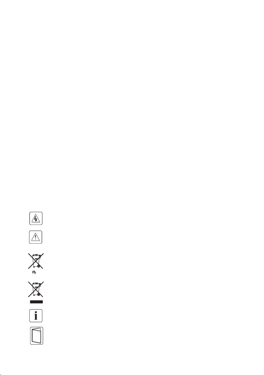
Special symbols
The following are examples of symbols used on the UPS or accessories to alert you to
important information:
RISK OF ELECTRIC SHOCK - Observe the warning associated with the risk of
electric shock symbol.
Important instructions that must always be followed.
Do not discard the UPS or the UPS batteries in the trash.
This product contains sealed lead acid batteries and must be disposed as it's explain
in this manual. For more information, contact your local recycling/reuse or hazardous
waste center.
This symbol indicates that you should not discard waste electrical or electronic
equipment (WEEE) in the trash. For proper disposal, contact your local
recycling/reuse or hazardous waste center.
Information, advice, help.
Refer to the user manual.

Safety of persons
RISK OF VOLTAGE BACKFEED. The system has its own power source (the battery).
Isolate the UPS and check for hazardous voltage upstream and downstream during
lockout-tagout operation. Terminal blocks may be energized even if the system is
disconnected from the AC power source.
Dangerous voltage levels are present within the system. It should be opened exclusively by
qualified service personnel.
The system must be properly grounded.
The battery supplied with the system contains small amounts of toxic materials. To avoid
accidents, the directives listed below must be observed:
- Servicing of batteries should be performed or supervised by personnel knowledgeable
about batteries and the required precautions.
- When replacing batteries, replace with the same type and number of batteries or battery
packs.
- Do not dispose of batteries in a fire. The batteries may explode.
- Batteries constitute a danger (electrical shock, burns). The short-circuit current may be
very high.
Precautions must be taken for all handling:
- Wear rubber gloves and boots.
- Do not lay tools or metal parts on top of batteries.
- Disconnect charging source prior to connecting or disconnecting battery terminals.
- Determine if battery is inadvertently grounded. If inadvertently grounded, remove source
from ground. Contact with any part of a grounded battery can result in electrical shock.
The likelihood of such shock can be reduced if such grounds are removed during
installation and maintenance (applicable to equipment and remote battery supplies not
having a grounded supply circuit).
Product safety
The UPS connection instructions and operation described in the manual must be followed
in the indicated order.
CAUTION - To reduce the risk of fire, the unit connects only to a circuit provided with
branch circuit overcurrent protection for :
63A rating, for 6kVA models,
100A rating, for 10kVA models
The upstream circuit breaker for Normal AC/Bypass AC must be easily accessible. The unit
can be disconnected from AC power source by opening this circuit breaker.
An additional AC contactor is used for backfeed protection and must comply with IEC/EN
62040-1 (the creep age and clearance distances shall meet the basic insulation
requirements for pollution degree 2).

Disconnection and overcurrent protection devices shall be provided by others for
permanently connected AC input (Normal AC/Bypass AC) and AC output circuits.
Check that the indications on the rating plate correspond to your AC powered system and
to the actual electrical consumption of all the equipment to be connected to the system.
For PLUGGABLE EQUIPMENT, the socket-outlet shall be installed near the equipment
and shall be easily accessible
Never install the system near liquids or in an excessively damp environment.
Never let a foreign body penetrate inside the system.
Never block the ventilation grates of the system.
Never expose the system to direct sunlight or source of heat.
If the system must be stored prior to installation, storage must be in a dry place.
The admissible storage temperature range is -25°C to +60°C with battery(-15°C to +40°C
without battery).
Special precautions
The unit is heavy: wear safety shoes and use vacuum lifter preferentially for handling
operations.
All handling operations will require at least two people (unpacking, lifting, installation in rack
system).
Straps are provided only for unpacking manually the unit from the carton; don’t use the
straps to carry the unit around. The unit can slip from the straps during handling (risk of
injury and product damage):
- keep 12in / 30cm minimum distance between the straps
- lift the unit carefully and keep it at low height
- keep the unit horizontal during unpacking.
Before and after the installation, if the UPS remains de-energized for a long period, the
UPS must be energized for a period of 24 hours, at least once every 6 months (for a normal
storage temperature less than 25°C). This charges the battery, thus avoiding possible
irreversible damage.
During the replacement of the Battery Module, it is imperative to use the same type and
number of element as the original Battery Module provided with the UPS to maintain an
identical level of performance and safety.

Contents
1. Introduction ...................................................................................................... 1
1.1 Environmental protection.......................................................................................................... 1
1.2 Electronic equipment protection .............................................................................................. 2
2. Presentation ...................................................................................................... 3
2.1 RT Front panel ........................................................................................................................... 3
2.2 RT Rear panels .......................................................................................................................... 3
2.3 EBM Front panel: ...................................................................................................................... 4
2.4 EBM rear panel: ......................................................................................................................... 4
2.3 Circuit diagram........................................................................................................................... 4
3. Installation ........................................................................................................ 5
3.1 Inspecting the equipment ......................................................................................................... 5
3.2 Unpacking the Unit .................................................................................................................... 5
3.3 Checking the accessory kit ...................................................................................................... 6
3.4 Install the unit ............................................................................................................................. 7
4. Power cables connection .................................................................................. 10
4.1 Access to terminal blocks (AC source to UPS) ................................................................... 11
4.2 Access to terminal blocks (PDU source to R/T UPS)(Optional) ........................................ 12
4.3 Parallel Installation and Operation (Optional) ...................................................................... 12
5. Operation ........................................................................................................ 17
5.1 Control panel ............................................................................................................................ 17
5.2 LCD description ....................................................................................................................... 19
5.3 Display functions ..................................................................................................................... 21
5.4 User settings ............................................................................................................................ 22
5.5 UPS startup and shutdown .................................................................................................... 23
5.6 LCD operation .......................................................................................................................... 25
6. Communication ............................................................................................... 33
6.1 Communication ports .............................................................................................................. 33

6.2 Intelligent Card (Optional) ...................................................................................................... 34
6.3 UPS Management Software .................................................................................................. 34
7. UPS maintenance ............................................................................................ 35
7.1Equipment care......................................................................................................................... 35
7.2 Transporting the UPS ............................................................................................................. 35
7.3 Storing the equipment............................................................................................................. 35
7.4 Replacing batteries ................................................................................................................. 36
7.5 Recycling the used equipment .............................................................................................. 37
8. Troubleshooting .............................................................................................. 38
8.1 Typical alarms and faults ........................................................................................................ 38
8.2 Silencing the alarm .................................................................................................................. 42
9. Specifications ................................................................................................. 43
9.1 Model specifications ................................................................................................................ 43
10 Glossary ........................................................................................................ 47
1. Introduction
Thank you for selecting UPS to protect your electrical equipment. The UPS has
been designed with the utmost care.
We recommend that you take the time to read this manual to take full advantage
of the many features of your UPS (Uninterruptible Power System).
Before installing your UPS, please read the booklet presenting the safety
instructions. Then follow the indications in this manual.
1.1 Environmental protection
Products are developed according to an eco-design approach.
Substances
This product does not contain CFCs, HCFCs or asbestos.
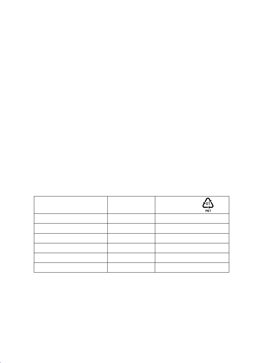
Packing
To improve waste treatment and facilitate recycling, separate the various packing
components.
The cardboard we use comprises over 50% of recycled cardboard.
•
Sacks and bags are made of polyethylene.
•
Packing materials are recyclable and bear the appropriate identification
•
symbol
Materials
Abbreviations
Number in
the symbols
Polyethylene terephthalat
High-density polyethylene
Polyvinyl chloride
Low-density polyethylene
Polypropylene
Polystyrene
PVC 03
PP 05
PS 06
PET
HDPE 02
LDPE 04
01
Follow all local regulations for the disposal of packing materials.
Product
The product is made up of recyclable materials.
Dismantling and destruction must take place in compliance with all local
regulations concerning waste. At the end of its service life, the product must be
transported to a processing center for electrical and electronic waste.
1

Battery
The product contains lead-acid batteries that must be processed according to
applicable local regulations concerning batteries.
The battery may be removed to comply with regulations and in view of correct
disposal.
1.2 Electronic equipment protection
The uninterruptible power system (UPS) protects your sensitive electronic
equipment from the most common power problems, including power failures,
power sags, power surges, brownouts, line noise, high voltage spikes, frequency
variations, switching transients, and harmonic distortion.
Power outages may occur unexpected, and the power quality will be erratic.
These power problems have the potential to corrupt critical data, destroy
unsaved work sessions, and damage hardware - causing hours of lost
productivity and expensive repairs.
With the UPS, you can safely eliminate the effects of power disturbances and
guard the integrity of your equipment. Providing outstanding performance and
reliability, UPS’s unique benefits include:
True online double-conversion technology with high power density, utility
frequency independence, and generator compatibility.
Selectable High Efficiency mode of operation.
Standard communication options: one RS232 communication port, one USB
communication port, one dry in port and dry out port.
Optional connectivity cards with enhanced communication capabilities.
Firmware that is easily upgradable without a service call.
2
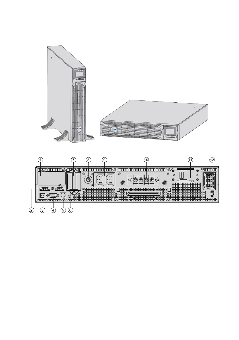
2. Presentation
2.1 RT Front panel
2.2 RT Rear panels
1. Intelligent slot
2. USB
3. RS232
4. RJ11 (only for RT model)
5. EPO
6. Parallel card (optional)
7. Dry IN/OUT
8. Input /Output terminal
(Standard model 5pole, IPL, IPN, PE,OPL,
OPN; long backup model has 2 version, one
is 5 Pole. Another is 7pole. 7pole add bat+,
bat-, and no external battery connector #10.)
9. Input switch
10. External battery connector
11. Maintenance bypass switch
(optional)
12. EBM connector
3
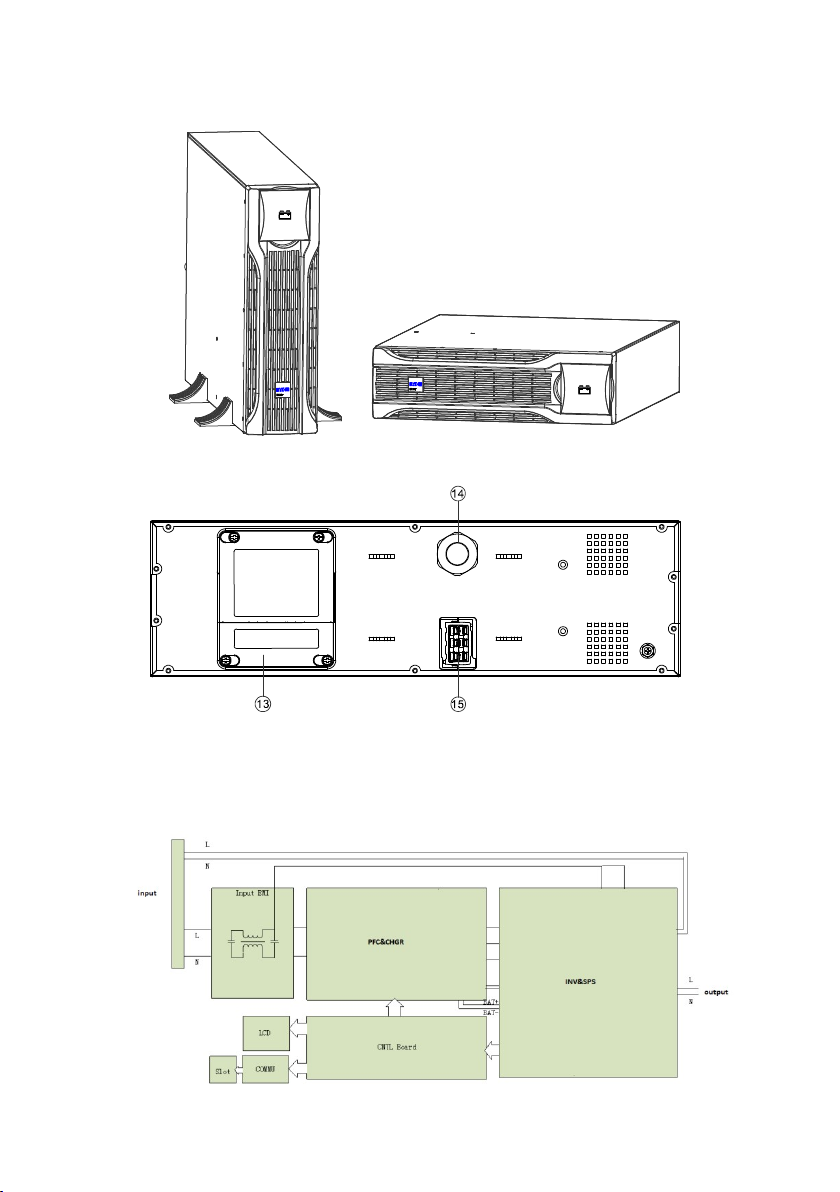
2.3 EBM Front panel:
2.4 EBM rear panel:
RT EBM
13. Fuse board cover (replace EBM fuse) 14. EBM plug
15. EBM connector
2.3 Circuit diagram
4
3. Installation
It is recommended to move the equipment to the installation site by using a pallet
jack or a truck before unpacking.
The system may be installed only by qualified electricians in accordance with
applicable safety regulations.
The cabinet is heavy, please install it with at least two peoples.
3.1 Inspecting the equipment
If any equipment has been damaged during shipment, keep the shipping cartons
and packing materials for the carrier or place of purchase and file a claim for
shipping damage. If you discover damage after acceptance, file a claim for
concealed damage.
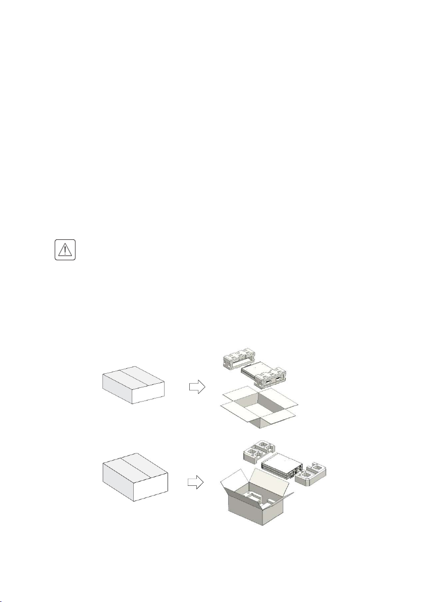
3.2 Unpacking the Unit
Unpacking the unit in a low-temperature environment may cause
condensation occurred in and on the cabinet. Do not install the unit until
the inside and outside of the unit are absolutely dry (hazard of electric
shock).
Remove the packing materials and lift the unit out with two people at least.
RT UPS
RT EBM
5

Note:
The cabinet is heavy, please see spec weight provided on the carton/label.
Do not lift the unit’s front panel and rear panel.
Discard or recycle the packaging in a responsible manner, or store it for future
use.
Packing materials must be disposed in compliance with all local
regulations concerning waste. Recycling symbols are printed on the
packing materials to facilitate sorting.
3.3 Checking the accessory kit
Verify that the following additional items are included with the unit:
DXRT
EBM
*
V
Battery power cable
USB cable
RS232 cable
Parallel cable
Dry contractor
EPO contractor
Stabilizer bracket
Extension plate
of Stabilizer bracket
Ear bracket
Rail kit
User manual
Eaton DX RT UPS
6000VAIN/10000VAIN
V V
O O
O O
V V
* *
V V
V V V
V V V
Eaton DX RT UPS
6000VAXLIN/10000VAXLIN
O O
V: standard configuration
*: assembled to unit
O: optional configuration
If you ordered other accessories, please contact with local sale center.
6
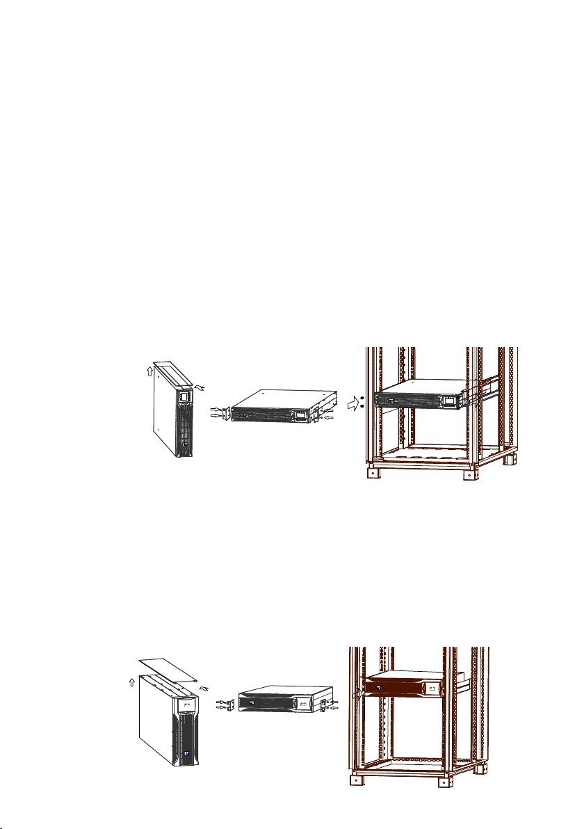
3.4 Install the unit
3.4.1 RT model:
Rack position installing
This procedure is suitable for 19 inch rack cabinet installation with a
minimum of 800mm depth.
UPS model
Identify the final position and keep ‘2U’ space for this installing.
Note that you already installed a ‘rail kit’ to rack cabinet for this operation,
and ‘1U’ rail kit is recommended to be selected.
1. Install ‘Ear bracket’ to the unit by the M4 screws (flat head).
2. Slide the unit into ‘rail kit’ and make sure tighten the ‘rack mounting
screw’.
EBM model
Identify the final position and keep ‘3U’ space for this installing, and it is
recommended to be installed below to UPS.
Note that you already installed a ‘rail kit’ to rack cabinet for this operation,
and ‘2U’ rail kit is recommended to be selected.
1. Install ‘Ear bracket’ to the unit by the M4 screws(flat head).
2. Slide the unit into ‘rail kit’ and make sure tighten the ‘rack mounting
screw’ .
7
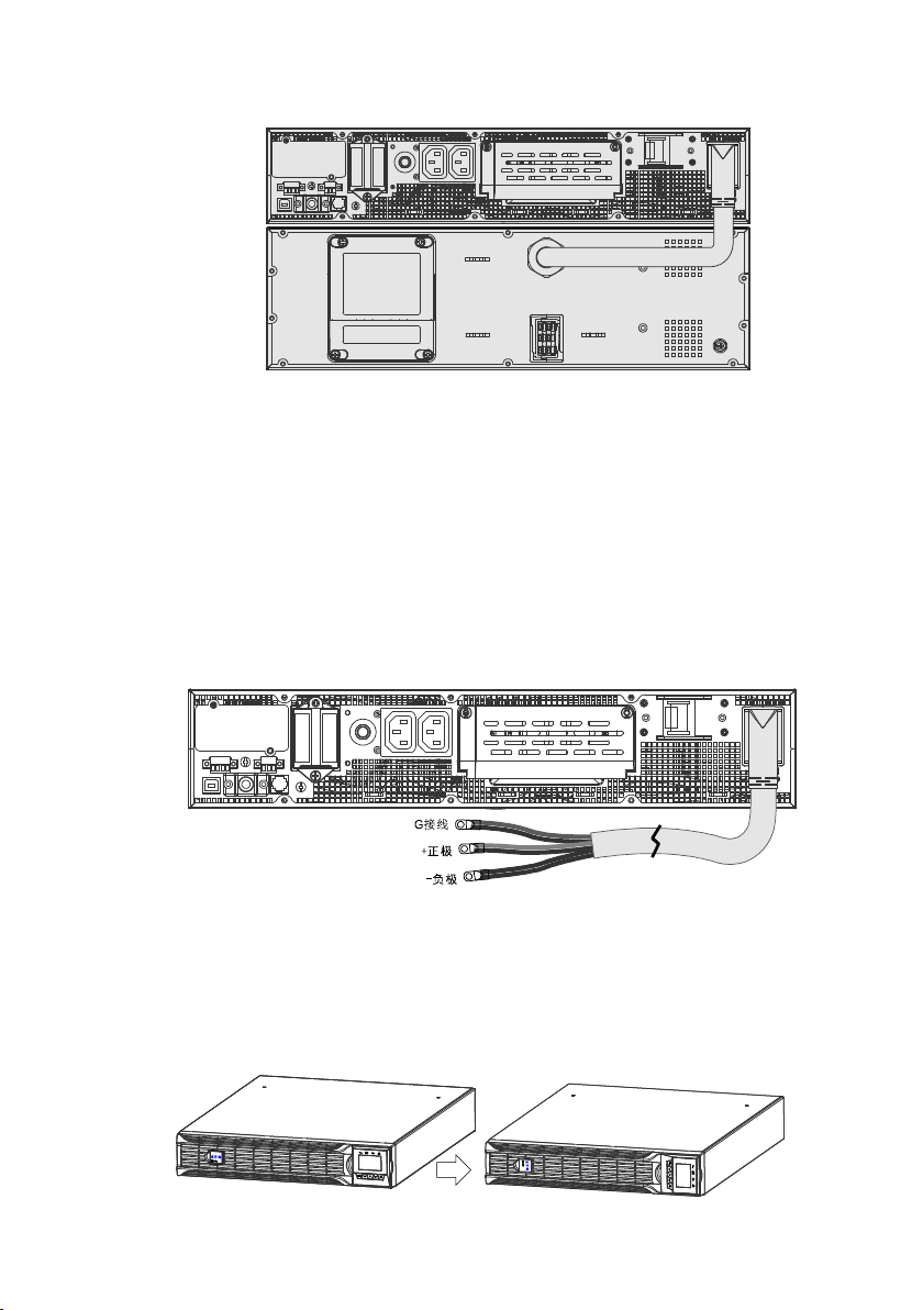
3. Connect EBM to UPS with ‘Battery power cable’.
Note:
This ‘Battery power cable’ may have different plug according to the number
of battery inside of this unit, please check the ‘Voltage ’ parameter on
rear-panel if it matches the UPS before connection.
The battery number can be adjusted from ‘16pcs*1 strings’ to ‘20pcs*1
strings’ for this unit, if you ordered other type EBM, please contact with local
sale center.
If installing additional unit, place it next to the previous unit in their final
location.
4. UPS external battery (1.8 meters long).
Note:
Before connecting the battery, please refer the wiring label “+”,“-”, and “G” .
Tower position installing
UPS model
1. Rotate the LCD model to tower direction.
8
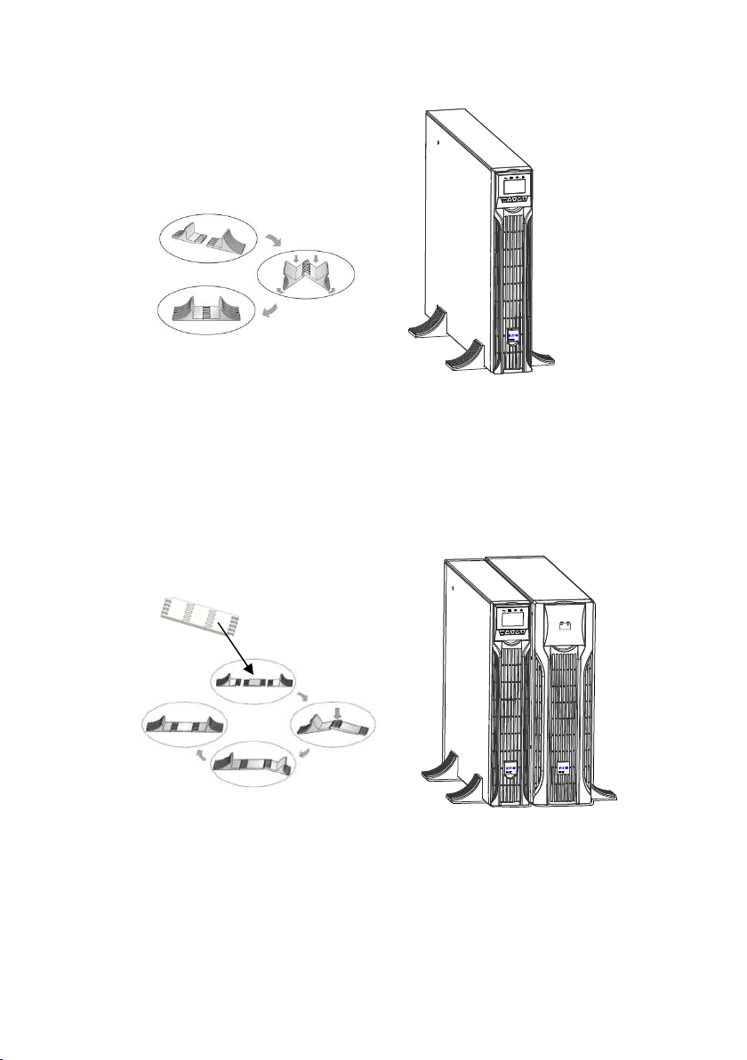
2. Set up the ‘Stabilizer bracket’, then take the unit into ‘Stabilizer bracket’.
EBM model
1. Set up the ‘Extension plate’ as below and install to ‘Stabilizer bracket’ from
UPS.
2. Take the UPS& EBM into ‘Stabilizer bracket’ individually.
3. Connect to UPS with ‘Battery power cable’--- Refer to rack position
installing.
Note:
This unit is recommended to be installed to UPS’s right side.
If installing additional unit, place it next to the previous unit in their final
location.
9
4. Power cables connection
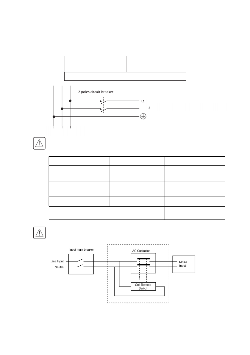
Recommended protective devices and cable cross-sections
Recommended upstream protection
UPS power rating Upstream circuit breaker
DX RT 6K UPS D curve – 63A
DX RT 10K UPS D curve – 100A
G N(L2) L1
Read the Safety instructions page 3 regarding backfeed protection requirements.
Recommended cable cross-sections
Model DX RT 6K UPS DX RT 10K UPS
Protective earthing conductor
Min cross section
Input L, N, G
Min conductor cross section
Input fuse 80A 100A
Output L,N,
Min conductor cross section
6mm^2 (8AWG) 10mm^2 (6AWG)
6mm^2 (8AWG) 10mm^2(6AWG)
6mm^2 (8AWG) 10mm^2(6AWG)
N(L2)
To UPS Normal AC / Bypass AC source.
It is recommended that an external isolating device should be installed between the
mains input and UPS as shown in Figure
AC Contactor: 208-240V, 63A (RT 6 kVA)208-240V, 100A (RT 10 kVA)
10
 Loading...