

Eaton Durant Eclipse Series, Durant 5775 40 Series, Durant 5775 41 Series Installation And Operation Manual
Durant
Eclipse Series Pulse Input
Flow Totalizers
Flow Ratemeters
Flow Batch Controls
Models: 5775X-40X - Totalizer w/Rate
5775X-41X - Batch Control
Durant
Installation and Operation
Manual Number 57750-900-03
PGM
BATCH
Table of Contents
1 Introduction
1 Description
10 Mounting
11 Wiring
21 Programming
Durant
Visit our Web Site at
w w w.durant.com
®
PGM
View Edit
Enter
Start
36 Run Mode
45 Diagnostics and Error
48 Specifications
Stop
Reset
Messages

INTRODUCTION / DESCRIPTION
This manual describes the installation of Durant models 5775X-40X and 5775X41X. Because of unique features, these counters may be used in a variety of applications. However, they are intended for use with pulsed output flowmeters; this
manual will focus on their use in flow applications.
This manual starts with a general description of flow applications and the Eclipse.
This should provide a useful reference point for the installer. Installers are the unsung heroes of industry who laugh in the face of the three most-feared words in the
English language: Some Assembly Required. Installers are often given a vague
objective and some equipment; in this case pipe, valves, a flowmeter, and a counter,
with which to accomplish the mission. It is then up to the installer to use his knowledge and ingenuity to make the system work.
The installation section of this manual follows the description. This provides detailed information on mounting, wiring, and programming the Eclipse. The installation section uses terms that were explained in the description. Installation is normally the most complex aspect of the Eclipse, therefore the installation section is
the largest section of this manual. The bad news is that the Eclipse is very versatile,
and through wiring and programming variations, can solve a variety of applications.
The manual must document all the possibilities. The good news is that most flow
applications will not require all of the wiring and programming choices that are
possible with the Eclipse. The key for the installer is to know what must be accomplished and to know what is in the Eclipse with which to do it.
There are three final sections in this manual. Run mode describes the operator
functions of the Eclipse. Diagnostics explains the self diagnostics and error messages that may appear on the display. The last section is specifications.
Description
Forty (40) model variations of the Eclipse are covered by this manual. The Eclipse is
either AC powered or DC powered. It consists of a base unit totalizer with 12 possible combinations of optional outputs, or a base unit batch control with 8 possible
combinations of optional outputs. While reading this description, it is important to
remember two things. First, all models can display flow rate. Second, the batch
control, known simply as the batcher to its fans, does all of the functions of the
totalizer. Check the part number breakdown chart on the next page to determine
what your unit is made up of. Read the description section(s) to identify how those
functions will be used in your particular application.
1
DESCRIPTION cont.
Eclipse Flow Model Numbers
5775X-4XX
Power Supply
0 = DC (9-30 VDC)
1 = AC (85-265 VAC)
Input / Function
0 = Pulse-Input Totalizer/Ratemeter
1 = Pulse-Input Batch Control
2 = Analog-Input Totalizer/Ratemeter
3 = Analog-Input Batch Control
*
Analog input models are covered
by manual #57750-920
*
Output Option
0 = No O ptio n
1 = Dual Relays (Standard on Batch)
2 = Analog Output (4-20mA & 0-10V
3 = Dual Relays & Analog Output
4 = RS-485 Communications
5 = Dual Relays & RS-485
6 = Analog Output & RS-485
7 = Dual Relays, Analog Output & RS-485
*
A = One Relay, One Transistor
B = One Relay, One Transistor, Analog Out
C = One Relay, One Tr ansistor, RS-485
D = One Relay, One Tr ansistor, Analog Out & RS-48 5
Base Unit
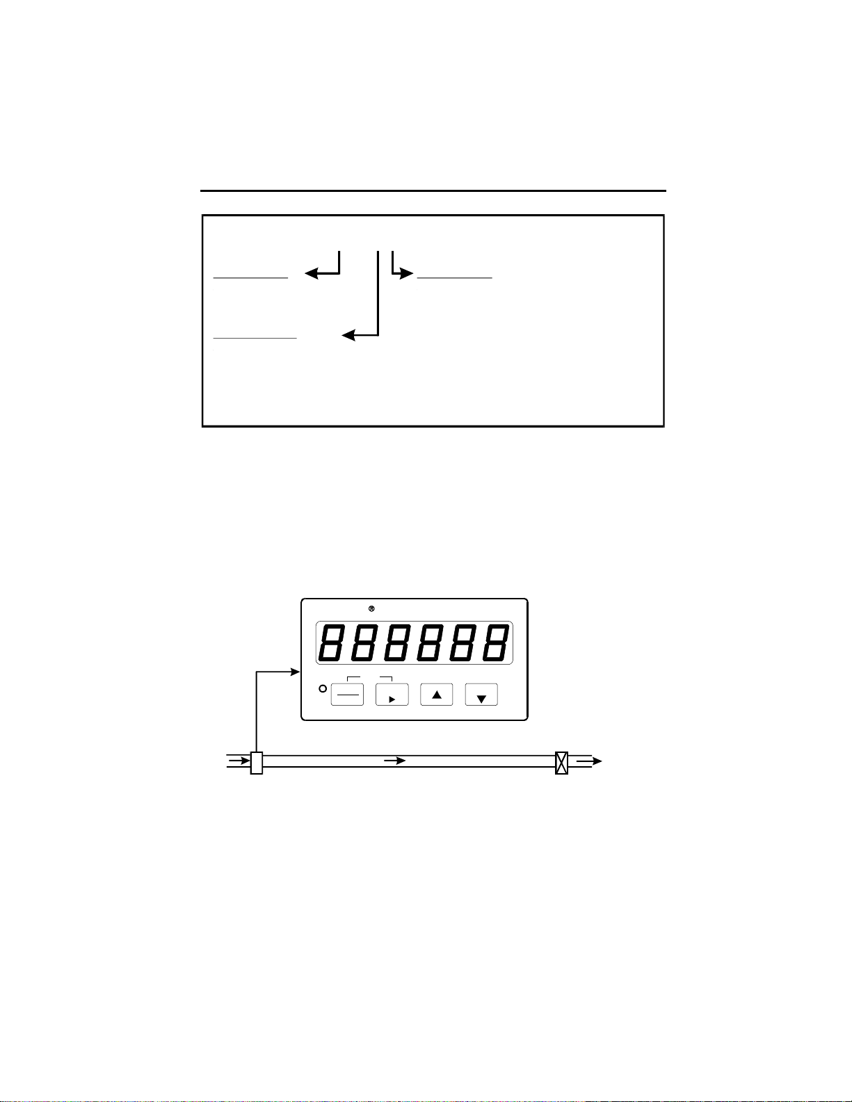
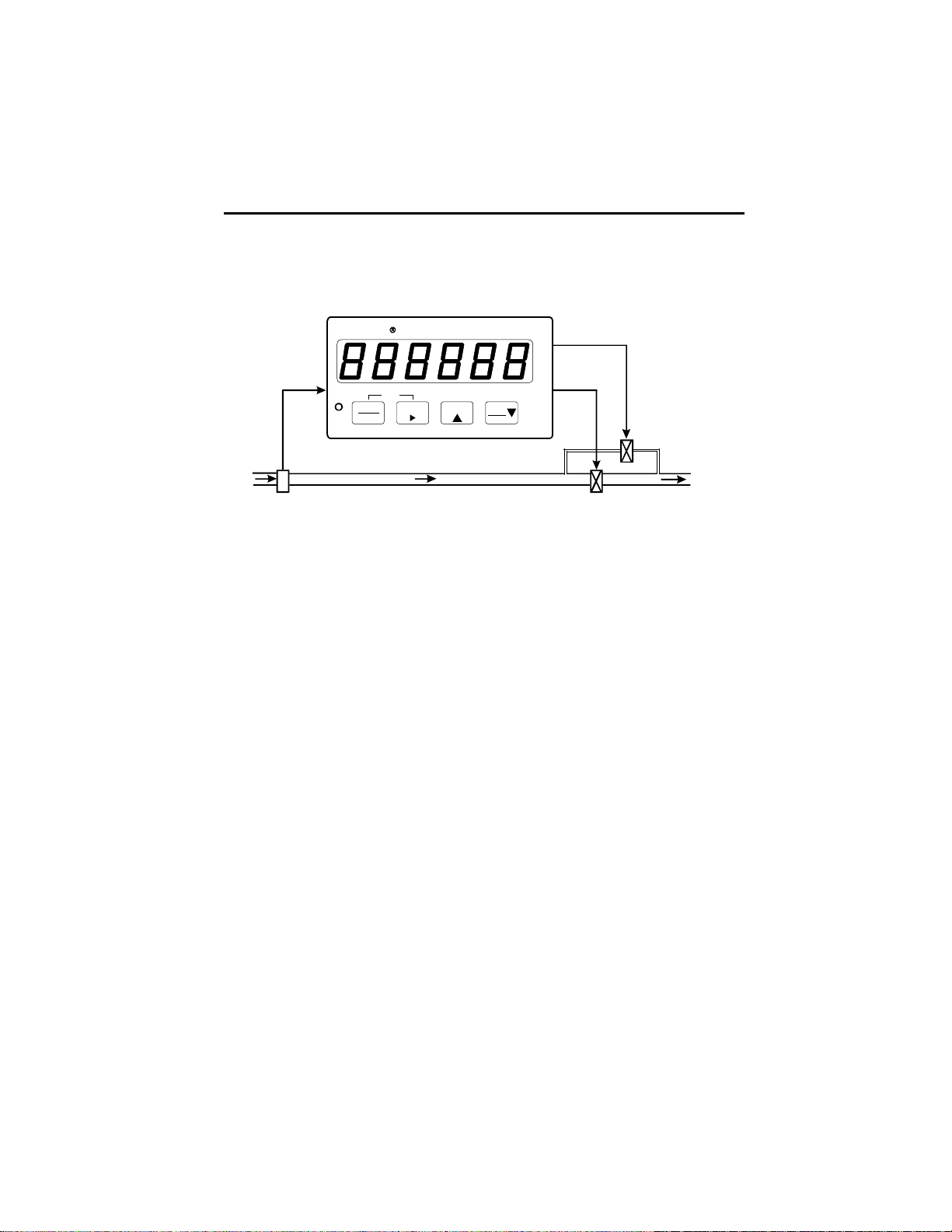
A totalizer is basically a counter that just counts. The Eclipse totalizer answers the
questions how much?, and how fast?. A typical application for a flow totalizer
would be a water meter for a building. As illustrated below, when a valve is opened
inside the building, water will flow through the pipe that feeds the building from the
water main. This flow causes the flowmeter to generate electrical pulses, sending it
to the totalizer.
Duran
Pulses In
PGM
t
PGM
View Edit
Enter
Reset
Flowmeter Valve
Flow
The totalizer accumulates these pulses and displays total water usage in gallons.
The totalizer can also display flow rate in units such as gallons per minute, based
upon how fast the pulses are coming in. All flowmeters are not created equal. Even
though two flowmeters may be the same model, they probably put out a different
number of pulses per gallon. The flowmeter manufacturer is aware of this and tests
each flowmeter after it is built. The actual number of pulses that the flowmeter puts
out per gallon (or pound, or liter, etc.) is known as the K factor, and is usually stamped
2
DESCRIPTION cont.
on the flowmeters label. Fortunately, the Eclipse can do the arithmetic to convert
pulses into familiar units of measure.
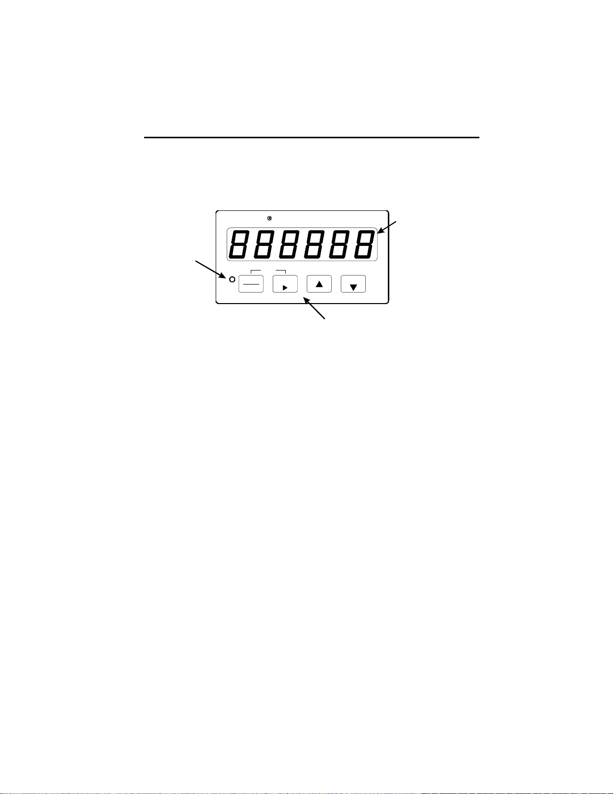
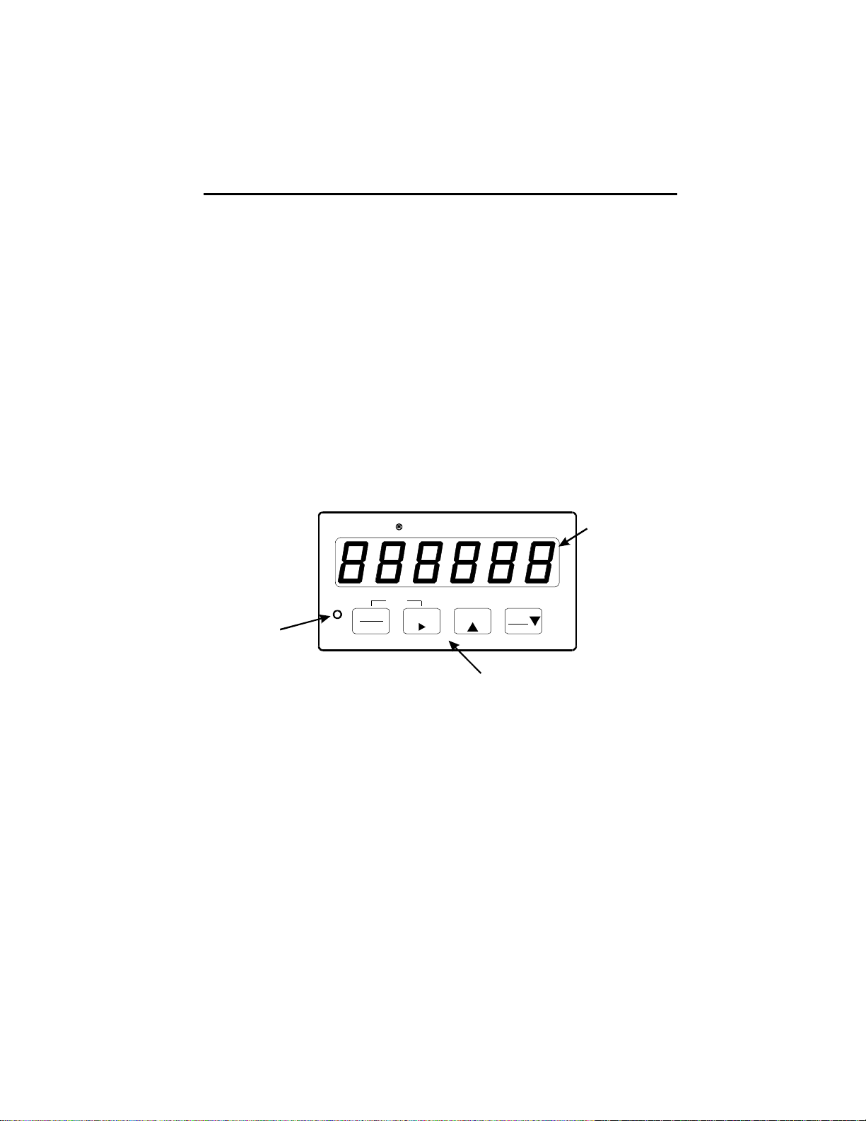
Once installed, normally only the front panel of the Eclipse totalizer will be visible. It
will look like this:
Six dig it
LED
Display
Program Mode
Indicating
LED
Durant
PGM
View Edit
Enter
PGM
Reset
Four Input Keys
The LED display dominates the front panel. The operator will view the total and rate
on this display. In totalizing applications, six digits (up to 999,999) is often not adequate. The installer has three options in this case, all available through programming.
1. The installer can program the Eclipse to divide the total by 10 (display up to
999,999 tens of gallons).
2. The installer can divide by 100 (display up to 999,999 hundreds of gallons).
3. The installer can display a 10 digit total in the form of the low five digits and the
high five digits on successive screens.
The display will also be used by the installer for programming purposes.
The four input keys will be used primarily by the installer for programming purposes,
but the operator can use them also for changing the display screen from total to rate,
for example. The reset key is programmable. For the base unit, the reset key can
reset the total, or do nothing for the operator.
The program mode indicating LED lets the installer know that he is in the program
mode.
The totalizer base unit has a control input board installed that allows the installer to
wire external switches to it to reset the total and to lock out the program mode from
the operator. These inputs may also perform other functions if the relay option board
is installed.
A batch control is a counter that opens a valve to allow flow to start and counts out
a certain preset volume of liquid as entered by the operator. It then shuts off the valve
after the batch has been delivered. This is a closed-loop control system. There are
3
DESCRIPTION cont.
two variations of batch control. The first, and most common is the single valve
approach represented by the diagram below.
Single Valve Batch Control
Durant
Relay 1
Pulses In
PGM
BATCH
Flowmeter Valve
PGM
View Edit
Enter
Start
Stop
Reset
Assume that a cosmetics manufacturer has just blended a 100,000 gallon vat of his
economy perfume, and that he wants to ship it to his customers in 55 gallon drums.
The operator enters 55 into the batch final preset by using the keys on the front
panel of the Eclipse batcher. When an empty drum is in place beneath the outlet
pipe, the operator presses the start key. This causes the batch final relay, (relay 1) to
turn ON, which in turn, opens the solenoid valve. With the valve open, perfume flows
from the vat to the drum. The flowmeter detects the flow and sends pulses to the
counter. The counter happily accumulates these pulses and counts up to 55. At this
point, the batcher realizes that the amount delivered to the drum is equal to the
amount entered by the operator in the batch final preset. The batch final relay turns
OFF, shutting the valve. When the operator has removed the full drum and placed
another empty drum under the outlet pipe, he again presses the start key and another batch of 55 gallons will be delivered.
Out
Flow
Once the batch delivery has been started, it will normally shut off automatically at the
batch final preset value. However, most users will want the ability to manually stop
the delivery as well. Assume that the operator had started his 55 gallon batch, and
then noticed that the drum had a hole in its side. The operator would then press the
front panel stop key, which would immediately turn the batch final relay OFF, shutting
the valve. Now the operator has a decision to make. Perhaps he can plug the hole
with a piece of chewing gum. In this case, he makes the repair and resumes delivery
of the batch from where he stopped by pressing the start key again. However, maybe
the operator determined that the hole could not be repaired. Then he would terminate the batch by resetting the counter. The resume function, completing a batch
after it had been manually stopped, and the terminate function, ending a batch after
a manual stop, are necessary functions of a batch control.
4
DESCRIPTION cont.
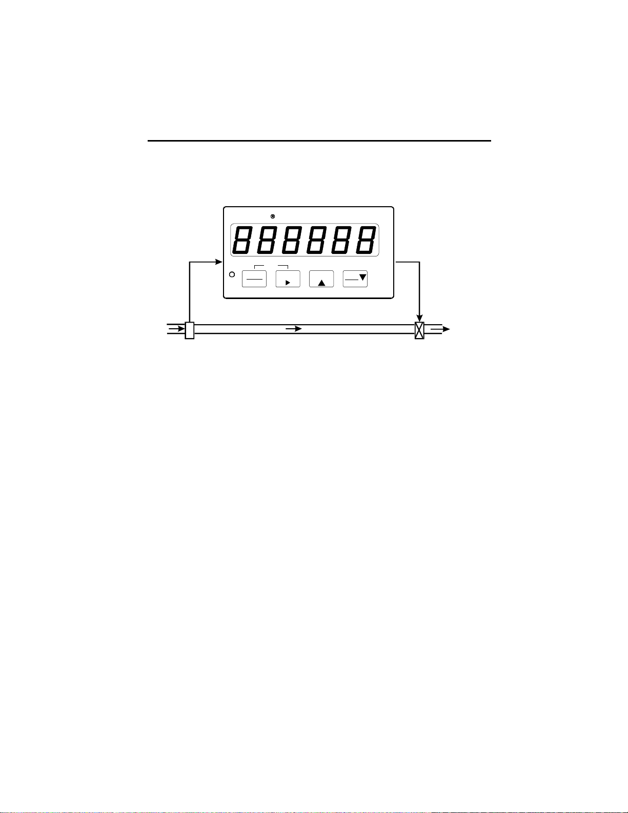
The second batch application is the two valve approach that uses both internal
relays of the batcher. Each relay controls a valve, as illustrated below:
Dual Valve Batch Control
Pulses In
Flowmeter
Durant
PGM
BATCH
PGM
View Edit
Enter
Start
Stop
Reset
Relay 1 Out
Relay 2 Out
Dribble Valve
Flow
Main Valve
The cosmetics plant made the single valve installation and soon 55 gallon drums
were being shipped out to customers everywhere. The installer stayed at the site to
observe the operation of the system and insure that it met his high standards.
Before long, the look of concern on the installers face made it clear that he was not
satisfied. Two things were troubling him. First, at the end of each batch, some extra
perfume was always delivered. The installer recognized that this was a clear case of
overrun. When the batcher delivered 55 gallons and turned OFF the valve, it took a
certain amount of time for the valve to actually close. During this time some flow
occurred. The amount of flow that occurs from the time that the batcher reaches the
batch final count until flow actually stops is called overrun.
The second observation that concerned the installer was the pounding that his
delicate plumbing took each time the valve closed. It was obvious that the shock of
going from a full flow state to a no flow state in less than one tenth of a second would
eventually cause an unauthorized exit in the system - a leak.
The installer knew that the solution for both problems was to use the dual valve
approach. This meant installing a small pipe around the valve. This pipe, the dribble
pipe, would also be equipped with a valve, known as a dribble valve. The dribble
valve is controlled by the batch final relay (relay 1), and the main valve is controlled by
relay 2, which is programmed to be the batch prewarn output. This fiendishly clever
setup operates in a simple manner. When a batch is started, both relays turn ON,
both valves open, and flow commences at a full flow rate. At a set value before the
batch final preset is reached, the prewarn relay turns OFF, closing the main valve,
and flow is reduced to the dribble rate. When the batch final preset is reached, the
batch final relay turns OFF, shutting the dribble valve and stopping the flow.
The set value before the batch final preset is the batch prewarn preset. It will
probably be set by the installer. The batcher does the arithmetic internally to deter-
5
DESCRIPTION cont.
mine at what batch count value the prewarn relay should turn OFF by subtracting the
batch prewarn preset from the batch final preset. Assume batch prewarn is set to 3.
When filling 55 gallon drums, the prewarn relay shuts off the main valve when the
batch reaches 52 gallons (55 minus 3). Should the operator decide to fill 30 gallon
drums, he simply changes the batch final preset to 30. The batcher would then shut
off the main valve when the batch reaches 27 gallons (30 minus 3). Although the
installer knows that prewarn operation is the result of careful planning, to the operator this has the appearance of magic. The batcher always knows when to shut off
the main valve, regardless of the preset batch size. If the operator concludes that the
installer has the power to create the mythical anticipating relay, it is not our duty to
confuse him with the facts.
Already some installers are thinking of other ways to use the batch control outputs.
For instance, some may wish to use the batch final relay to control a valve, and the
batch prewarn relay to operate a pump. This manual simply cannot cover all the
possibilities.
Once installed, normally only the front panel of the Eclipse batcher will be visible. It
will look like this:
Six digit
LED
Display
Program
Mode
Indicating
LED
Durant
PGM
BATCH
PGM
View Edit
Enter
Start
Four Input Keys
Stop
Reset
The LED display dominates the front panel. The operator will view various counters,
presets, and the rate on this display. The installer will view and edit programming
selections on the display.
The four input keys have operator and installer functions. The operator may use
them to change display screens from count, to preset, to rate, etc. and possibly to
reset counters. The operator may also use these keys to start, stop, resume, and
terminate batch delivery.
The program mode indicating LED lets the installer know that he is in the program
mode when it is ON. This LED will flash ON and OFF for the operator when a batch
is running. Once a batch has been stopped, either manually or automatically, the
LED will remain OFF until another batch is started.
The installer is probably now thinking well, it seems that we have batch delivery
pretty well covered, but how about those totalizer functions that this thing is sup-
6

DESCRIPTION cont.
posed to do? This manual is glad you asked that question. There are actually two
other counters inside the box. One is a totalizer that counts along with the batch
counter. However, while the batch counter is reset at the beginning of each batch, the
totalizer is not reset; it continues to count up. The cosmetics manufacturer resets his
totalizer each time he blends another 100,000 gallon vat. As the batch counter delivers 55 gallon drums, the totalizer counts the total amount delivered. When the totalizer reaches 100,000, it is time to blend another vat of perfume and reset the totalizer.
The third counter is the cycle counter. The cycle counter keeps track of how many
batches had been delivered; it counts the number of batches. The mere presence of
the cycle counter opens the door to some interesting variations of batch delivery
automation. The batch counter may be programmed to auto recycle. This is done by
programming a time in the range of 0.1 to 9.9 seconds for batch recycle time. In this
case, the operator starts the initial batch manually. Once the first batch is delivered,
the batcher stops for the duration of the auto recycle time and then automatically
starts another batch. This may continue until the operator manually stops the process with the cycle counter showing the number of batches run. However, the cycle
counter has a setpoint, called cycle preset, which will stop the process automatically after that number of batches has been delivered. This type of operation is
known as cycle autostop. If a batch autorecycle time of 0.0 is programmed, the
batcher stops after each batch has been delivered, and each batch must be manually started by the operator.
Two other things can happen when the cycle counter reaches the cycle preset, cycle
reset and cycle output. The cycle counter will automatically reset to zero if it is programmed to reset at cycle setpoint. This feature would normally be employed in
combination with the use of an output at cycle setpoint. If both relays are already
used to deliver the batch, or if relay 2 is used for another function, this will not be
possible. Refer to the relay output option description on page 31. If relay 2 is available to be used as a cycle output, the cycle counter can cause any combination of the
following events at the cycle preset value:
1. Cycle autostop or no autostop.
2. Cycle counter reset or continue to count up.
3. Cycle output or no output.
When all is said and done, most users will simply use the cycle counter to count
batches and nothing else. However, the installer will certainly appreciate knowing
the possibilities.
There are a few final points to be made about the batchers base unit. First, it also
provides an alarm output at a preset rate, if relay 2 is not used for another function.
Second, the relay output board, an option for the Eclipse totalizer, is always included
in the batcher. The outputs are described in the relay output option description on
page 8. Third, a control input board is installed in the unit. The board has three
7

DESCRIPTION cont.
inputs that may be programmed to do a number of functions such as counter(s)
reset, unlatch outputs, program mode lockout, and the batch control start and stop
functions.
Relay Output Option Board
Two types of output boards are available for the Eclipse. One is a dual relay as
indicated by the last digit of the part number being a 1, 3, 5, or 7. The other is a single
relay/single transistor as indicated by the last digit of the part number being an A, B,
C, or D. In either case, output 1 is a relay. One of the output option boards is standard
in the batch control unit. Output 1 is dedicated as the batch final output in the batcher.
Output 2 can be programmed to one of the totalizer output functions described
below, or to the batch prewarn or cycle setpoint function. The batch prewarn output is
described on page 5. As a cycle setpoint output, it will turn ON when the cycle count
reaches the cycle preset value, and turn OFF either after a programmable time in the
range of 0.01 to 99.99 seconds elapses, or after an unlatch 2 input occurs. The
unlatch input can be either a control input or a front panel key programmed to unlatch
2.
If the output board is installed in a totalizer base unit, either output can be programmed to perform one of the following totalizer output functions:
1. Totalizer setpoint. This option is not available if the totalizer is programmed to
10 digit total. Turns ON when the totalizer counts to a number greater than or
equal to the totalizer preset value. Turns OFF either after a programmable
time in the range of 0.01 to 99.99 seconds elapses, or after an unlatch input
occurs. If the output is programmed to latch (no timeout), the output will be
checked at each input pulse until an unlatch input occurs, even after power
has been cycled OFF and then ON to the unit.
2. Rate low setpoint. Turns ON when the rate is less than or equal to the rate low
setpoint. However, from a start condition (power up for the totalizer; batch start
for the batcher), the rate reading must first become greater than or equal to
the rate low setpoint before this alarm feature is enabled. Turns OFF after a
programmed timeout in the range of 0.01 to 99.99 seconds, or when an
unlatch input occurs, or when the rate becomes greater than the setpoint
(follows mode). This output is updated each time the rate display updates.
3. Rate high setpoint. Turns ON when the rate is greater than or equal to the rate
high setpoint. Turns OFF after a programmed timeout, or when an unlatch
input occurs, or when the rate becomes less than the setpoint (follows mode).
4. Rate low-high setpoint. Turns ON when the rate is less than or equal to the
rate low setpoint, OR is greater than or equal to the rate high setpoint. If the
rate low setpoint is greater than the rate high setpoint, the output will be ON
when the rate is greater than the rate high setpoint AND less than the rate low
setpoint. Follows mode only.
8

DESCRIPTION cont.
5. Totalizer pulse output. Puts out a timed pulse for each totalizer count. This
signal is intended to go to a remote totalizer. The pulse width ON time is
selectable to be either 500 +/- 84 msec, 2 msec, or 50 msec. The minimum
OFF time is the same as the ON time. Regardless of the totalizer display
mode selected for the Eclipse (i.e. divide by 1, 10, or 100), the totalizer pulse
output operates in the divide by 1 mode. The totalizer pulse output has a
9,999 count register. Because of the nature of this output, it is recommended
that a transistor output be used for this function.
Analog Output Option Board
Sometimes known as analog retransmission, the installer can assign the output to
follow displayed rate, or total, or batch count, or cycle count. Both 4-20 mA and 0-10V
outputs are given; however they are not independently programmable. The installer
programs not only the assignment, but the offset and full scale values. Both outputs
follow the assigned count or rate and go from minimum value (4 mA and 0V) to
maximum value (20 mA and 10V) as the displayed count or rate goes from offset
value to full scale value. Both outputs are electrically isolated from all other circuitry
inside the Eclipse.
RS 485 Serial Communications Option Board
This option board allows a host device, such as a computer, to download and read
programming selections, and to perform most of the run mode operator functions
such as read count and rate, enter setpoints, reset counters, and start and stop
batch delivery.
This manual does not contain information on the serial command protocol or the
serial command list. That information is contained in the 57750 serial specification
and obtainable by contacting the Durant Literature Department at 800-540-9242
(US and Canada), or 920-261-4070, or by FAX at 920-261-9097.
9
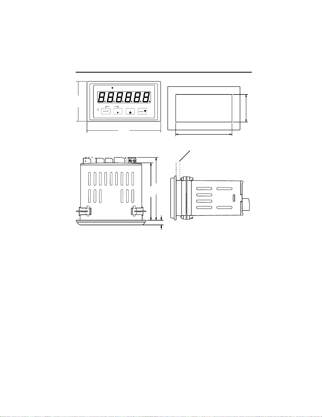
MOUNTING
Durant
2.19
PGM
BATCH
PGM
View Edit
Enter
4.04
Start
Stop
Reset
3.622 +/- .031
[92.00]
Panel Cutout
Max. Panel Thickness .190 [4.83]
3.63
3.31
.27
Mounting Instructions
1. Slide mounting gasket (not shown) over unit body until adhesive surface
makes contact with the front bezel.
[45.00]
1.772 +/- .024
2. Slide unit into cutout in panel.
3. Attach mounting clips and screws.
4. Tighten screws until unit is firmly in place. DO NOT OVERTIGHTEN screws
to the point of squeezing the gasket out from behind the bezel.
10
WIRING
WIRING AND DIP SWITCHES
All wiring to the counter is done to rear terminal, de-pluggable connectors. Up to six
headers accept the wired connectors on the counter. All units have at least three
headers, power input, count input and control input. The relay output header is
installed in the batch control base unit and is optional for the totalizer. Any combination of two additional circuit boards with headers may be installed. These option
boards are RS 485 serial communications and analog output. The option boards
occupy specific locations in the counter and are not interchangeable. All boards are
keyed to prevent installation in the wrong location.
Disconnect all power before wiring terminals. A safety hazard exists if this
precaution is not observed. Treat all control and count inputs as hazardous
since they may carry line voltage.
A switch shall be included in the building installation:
It shall be in close proximity to the equipment and within easy reach of the
operator.
It shall be marked as the disconnecting device for the equipment.
Switches and circuit breakers in Europe must comply with IEC 947.
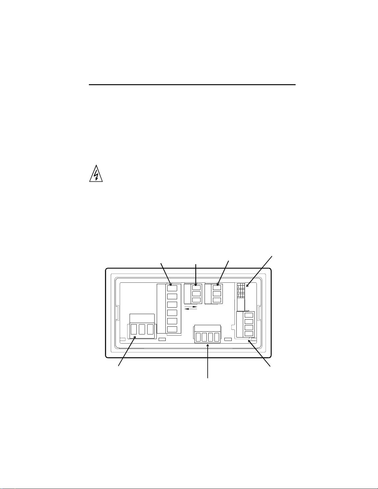
Rear Terminal Layout
Durant
1
Power Input
2 Terminals for DC
Powered Units
3 Terminals for
AC Powered Units
Relay
Output
®
RS485
Communications
1
1
Control Input
11
Analog
Output
DIP Switch
Count Input
WIRING cont.
Terminal Connector Ratings
AC or DC Power Input / Relay Output: 10A, 250VAC;
Wire size: 12-24AWG (3.1mm2 - 0.24mm2), 600V.
RS485 / Analog Output / Flowmeter Input / Control Input: 8A, 125VAC;
Wire size: 16-28AWG (1.3mm2 - 0.1mm2), 300V.
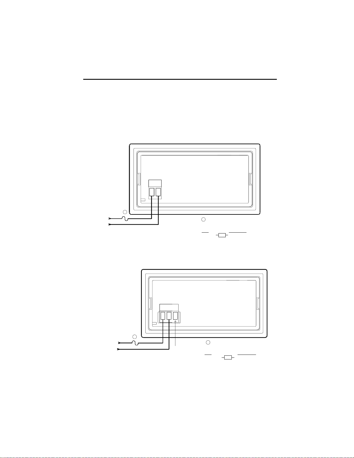
DC Power Input (for DC powered models 57750-4XX)
®
1
Externa l F use Size
U.S.
2 AMP, 50 V
Time Delay
Power In
9-30 VDC
12 VA
Durant
12
1
1
+
{
-
AC Power Input (for AC powered models 57751-4XX)
Durant
®
123
1
No Internal Fuse
European
T2A, 50 V
Time Delay
Power In L1
85-265 VAC L2
47-63 Hz
20 VA
{
1
Not
Used
0.2 AMP, 50 V
Time Delay
No Intern a l F u se
1
External Fuse Size
U.S.
European
T200mA, 250 V
Time Delay
12

WIRING cont.
Programming Considerations for Power Up Operation
What can there possibly be to program that has anything to do with power wiring?
Considering this from the operators perspective, what does he expect to see when
he turns on the power? The default menu column d (page 28) has four (4) programming blocks. The set default blocks d3 and d4 are the domain of the installer or
maintenance person, but the other two blocks affect what the operator can see and
do at power up. Block d1 sets the power up display. Should the unit always display
rate, or count at power up, or should it just come up to the display that was showing
when the power went down? Block d2 determines what the totalizer displays, either
a six digit total in divide by 1, or 10, or 100 mode, or a 10 digit total.
Speaking of the front panel keys, what should they do for the operator? The program
mode is entered using these keys, but it is a good idea to lock out the program from
the operator. This is done by programming a control input (in column L, page 29) to
do one of the lockout functions and then wiring that input to common as shown in the
control input wiring diagram. For totalizers with the relay option and for all batchers,
the reset key may perform an output unlatch function as well as, or instead of, the
reset function. This is set by programming block L4. Batchers have start and stop
keys available to the operator. Both keys can do one or more functions depending
upon the choices made in blocks L5 and L6 respectively.
13
WIRING cont.
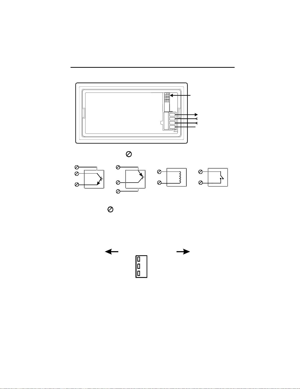
Flowmeter Input Wiring and DIP Switches
Durant
®
4
3
2
1
DIP Switch Position 3
+12 VDC Out
Flowmeter Input
Inhibit Input
Ground
X
Typical Flowmeter wiring (3 denotes terminal number)
NPN
4
OUT
3
1
COMMON
DIP 1 ON
4
+
PNP
+
OUT
3
1
COMMON
DIP 1 OFF
2 Wire MAG Pickup
3
1
DIP 3 ON
Contact (Reed Switch , etc.)
3
1
DIP 2 ON
The inhibit input (2 ) is wired the same way, and DIP switches 1, 2, and 3 are set
accordingly.
Sensor Power Out
12 VDC, 75 mA max, short circuit protected
Dip Switch Settings
OFF ON#
Single Ended
Fast Respon se (>50 Hz)
Sourcing (PNP) Input
3
Mag Pickup
Slow Response (<50 Hz)
2
Sinking (NPN) Input
1
14

WIRING cont.
Programming Considerations for Flowmeter Input and DIP Switch Definitions
The inhibit input will normally not be used. The count inhibit function means that the
counter will ignore flowmeter pulses when inhibit is active. This is handy at some
times, such as when the system is being purged. However, experience has shown
that most users do not care to use this function. Inhibit inputs on counters around
the world are aware of this fact; because of it, inhibit inputs generally suffer from lack
of self-esteem. Inhibit inputs are the original Maytag
tive, caring counter manufacturer that has decided to do something about this. The
inhibit input on the Eclipse is programmable (in block F1, page 26) to either do its
traditional inhibit duty, or to select between two pre-loaded K factors. This opens up
a number of application possibilities, some bizarre, some simply clever. If one K
factor is the number of pulses per gallon and the other K factor is the number of
pulses per liter, the user can go from counting in gallons to counting in liters and vice
versa simply by throwing a switch. Gallons to pounds conversion is another likely
scenario.
Setting the DIP switches can be an adventure since there are a wide variety of
flowmeter types and there is no standard output pulse signal. Furthermore, signal
conditioning devices, such as flow transmitters, may change the electrical characteristics of the signal. The most common flow signal is a differential, AC voltage
generated by a paddlewheel flowmeter. This is a two wire signal, and the output
frequency can easily exceed 200 Hz. Mag pickups are sink and source, so dont
worry about DIP switch 1, just turn 2 OFF and 3 ON. Contact outputs, such as reed
switches, are much less common. They can be set up as sink, as shown in the
diagram, or source. Since the diagram shows how to wire them as sinking sensors,
use that method. Contact inputs will always be low speed, so switch 2 is ON.
®
repairman. Durant is a sensi-
Transistor output signals are generally three wire, since the transmitter usually
requires DC operating power. The Eclipse puts out 12 VDC for these types of sensors. Transistors are either NPN or PNP. NPN outputs are sinking outputs; they
provide the path to ground. PNP outputs are sourcing; they provide the path to positive. These signals are considered single ended because they are referenced to
common (ground). They can easily be high frequency signals. Switches 2 and 3
should be OFF, and switch 1 is OFF for PNP, and ON for NPN.
15
 Loading...