

Eaton DS7 Series Instructional Leaflet
Instructional Lea et IL03901004E
Effective February 2011
DS7 series soft start controllers,
Frame 2 (16–32A)
Introduction
Eaton’s DS7 solid-state soft start controller is an
electronic, self-contained panel- or enclosuremounted motor soft-starting device. It provides
three-phase induction motors with a smooth start,
both mechanically and electrically. The DS7 line
uses four silicon-controlled rectifiers (SCRs) that
are connected in a full wave-power bridge on two
phases. The voltage and current applied to the
motor are controlled by varying the SCR conduction period. This, in turn, controls the torque developed by the motor. After the motor reaches speed,
a bypass relay is energized to bypass the SCRs.
The DS7 is designed to fulfill the industrial service
requirements of applications such as chiller starters, pump panels, and machine tools. This device
meets all relevant specifications set forth by UL姞
508, IEC 60947-4-2, CE, C-Tick, and CSA姞.
This leaflet covers basic installation and setup. No
publication can take into account every possible
situation. If you require further assistance with any
aspect of this product or a particular application,
contact Eaton.
Inspection
General
Upon receipt of the unit, verify that the catalog
number and unit options stated on the shipping
container match those stated on the order/
purchase form.
Inspect the equipment upon delivery. Report any
carton damage to the carrier prior to accepting the
delivery. Have this information noted on the freight
bill. Eaton is not responsible for damage incurred
in shipping.
Unpacking
Remove all packing material from the unit. Be
sure to remove all packing material from the
lug location.
Check the unit for any signs of shipping damage.
If damage to the product is found after unpacking,
report it to the freight company. Retain the packing
materials for the carrier to review.
Verify that the unit’s catalog number and options
match those stated on the order/purchase form.
Instructional Lea et IL03901004E
Effective February 2011
DS7 series soft start controllers, Frame 2 (16–32A)
Storage
It is recommended that the unit be stored in its original shipping
box/crate until it is to be installed.
The unit should be stored in a location where:
•
The ambient temperature is between –13° to 140°F (–25° to 55°C)
•
The relative humidity is between 0% and 95%, noncondensing
•
The environment is dry, clean, and noncorrosive
•
The unit will not be subjected to high shock or vibration conditions
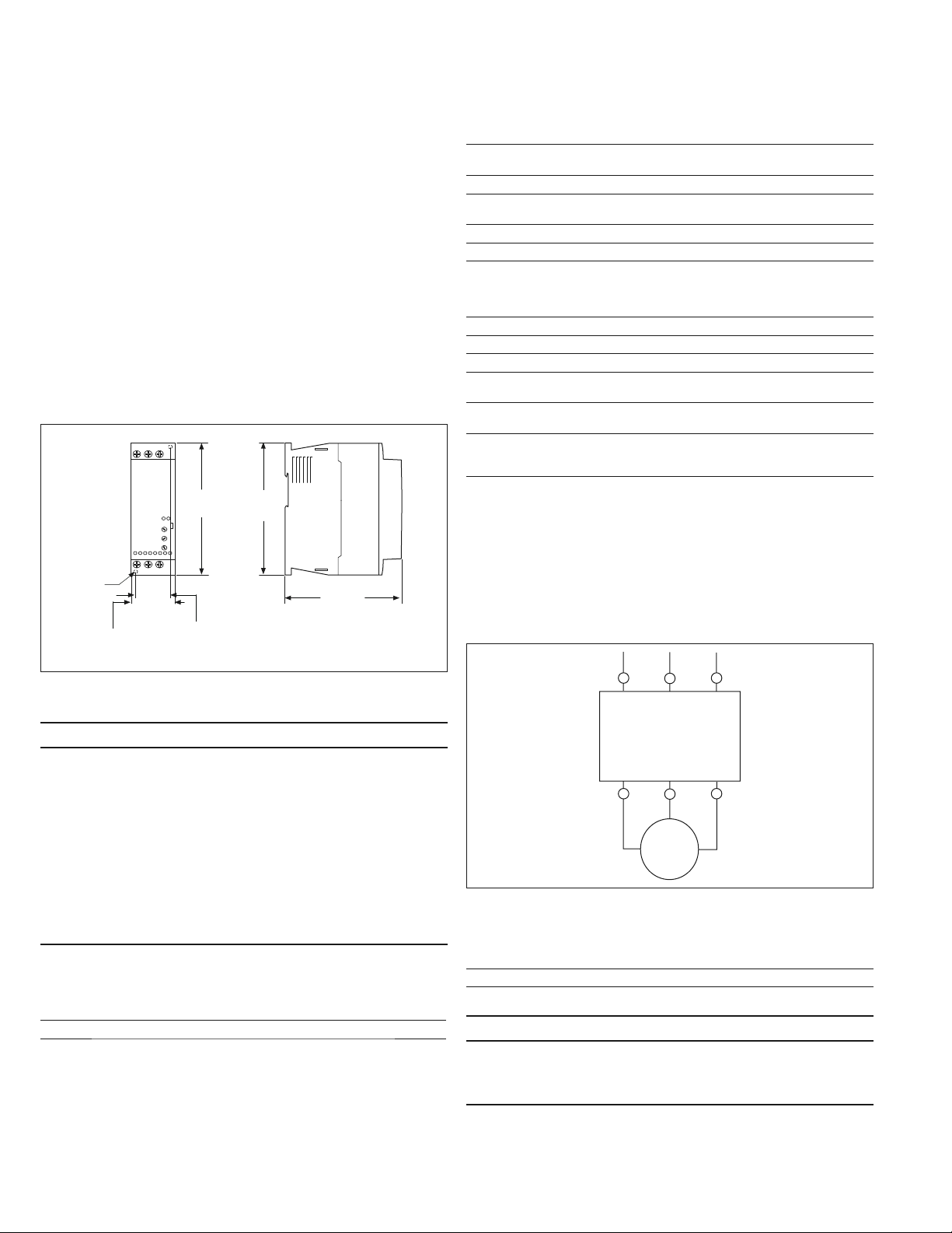
Mounting instructions
The DS7 solid-state soft start controller is easy to mount. It does
not require any special tools. To aid you with panel layout, refer to
the dimension drawings shown in Figure 1. Drill and tap holes per
mounting hole/slot locations as shown. To mount the unit, use all the
hardware specified in Table 1 of this leaflet. Tighten to the specified
torque.
M4
1.78
(45.0)
16–32A modelsFigure 1.
5.91
(150.0)
1.38
(35.0)
5.51
(140.0)
4.65
(118.0)
Environmental requirementsTable 2.
Description Requirement
Operating temperature 32° to 104°F (0° to 40°C) up to 140°F (60°C) with
derating of 1% of rated current per Kelvin
Storage temperature 13° to 140°F (–25° to 60°C )
Elevation Up to 1000m; up to 2000m with derating of 1% rated
current for each 100m
Humidity Functional to 95% noncondensing
Operating orientation Less than 30 degrees from horizontal
Minimum clearance—
Upper and lower
2.165 in (55 mm) to a wall, 0.984 in (25 mm) to an
upper and lower NZM1 (size 1), 1.378 in (35 mm)
to an NZM2 (size 2), consult documentation of the
breaker used (ionization emissions)
Minimum clearance—sides 0.0 in (0 mm)
Minimum clearance—face 0.198 in (5 mm)
Shock resistance 8g for 11 ms in any direction
Vibration resistance 2M2 EN 60721-3-2: 10g (3.5 mm amplitude,
9 to 200 Hz)
Environment Suitable for installation in a pollution Degree 2
environment
Emissions The device is suitable for use in industrial
environments in accordance with EN 55011/22
Class A
Power wiring
Using the wiring diagram in Figure 2 and Table 3 as guides, connect
the line and motor wiring in accordance with appropriate local and
national codes.
To provide optimum motor protection, the line and motor power wiring ote: N
should be tightly bundled and run perpendicular to the orientation of the DS7.
Soft start controller to motor cable length is not to exceed 325 ft (100m).
5
1
L2 L3
L1
3
DANGER—HIGH VOLTAGE
HAZARDOUS VOLTAGE CAN CAUSE ELECTRIC SHOCK AND BURNS. TO
AVOID SHOCK HAZARD, DISCONNECT ALL POWER TO THE CONTROLLER,
MOTOR, OR OTHER CONTROL DEVICES BEFORE ANY WORK IS PERFORMED
ON THIS EQUIPMENT. FAILURE TO DO SO WILL RESULT IN PERSONAL
INJURY, DEATH, OR SUBSTANTIAL PROPERTY DAMAGE.
DO NOT APPLY A DISCONNECT DEVICE ON THE OUTPUT OF THE DS7
SOFT START CONTROLLER UNLESS A MEANS TO TURN OFF THE DEVICE
WHEN DISCONNECT SWITCH IS OPEN IS UTILIZED. OPENING THE
DISCONNECT WHILE THE SOFT START CONTROLLER IS OPERATING MAY
CAUSE A MALFUNCTION. CLOSING THE DISCONNECT SWITCH WHILE THE
SOFT START CONTROLLER IS OPERATING WILL RESULT IN POTENTIAL
EQUIPMENT DAMAGE AND PERSONNEL HAZARD.
Mounting hardware and torque specificationsTable 1.
Screw Size +
Flat and Lock
Washer Quantity
M4 4 10 lb-in (1.2 Nm) 0.9 (0.4)
Torque
Requirements
Unit Weight
Lbs (kg)
DS7
T1
4
T2
M
3~
2
T3
6
Power wiring diagramFigure 2.
Power wire sizing and torque requirementsTable 3.
Wire Size Torque Wire Strip Length
18–6 AWG 26.55 lb-in 10 mm
DANGER
HAZARDOUS VOLTAGE. WILL CAUSE DEATH OR SERIOUS INJURY.
HAZARDOUS VOLTAGE IS PRESENT IN THE OFF/STOP STATUS OF THE SOFT
START CONTROLLER WHEN THE LINE VOLTAGE IS ENERGIZED.
2
EATON CORPORATION www.eaton.com
DS7 series soft start controllers, Frame 2 (16–32A)
Instructional Lea et IL03901004E
Effective February 2011
Product selection—horsepower ratings
Please refer to Application Note AP03901006E for additional information on proper size selection.
10 second ramp, one start per hour, 300% current limit at 40°C Table 4.
Rated
Current
(A)
Motor Power (hp) Maximum
Allowable
Breaker Size
Maximum
Allowable
Fuse Size
Recommended
XTOB Overload
(Direct Connect)
15.2 3 5 10 HFD3035 25A Class RK5 XTOB016CC1 XTOE020CCS XTPR016BC1 XTPAXTPCC DS7-340SX016NO-N
22 5 7.5 15 HFD3060 40A Class RK5 XTOB024CC1 XTOE045CCS XTPR025BC1 XTPAXTPCC DS7-340SX024NO-N
32 7.5 10 20 HFD3070 50A Class RK5 XTOB032CC1 XTOE045CCS XTPR032BC1 XTPAXTPCC DS7-340SX032NO-N
Recommended
XTOE Overload
MMP
Connection
Kit to MMP
Catalog
Number200V 230V 480V
DS7-342SX016NO-N
DS7-342SX024NO-N
DS7-342SX032NO-N
Recommended
XTOE Overload
MMP
Connection
Kit to MMP
Catalog
Number200V 230V 480V
Rated
Current
(A)
10 second ramp, one start per hour, 400% current limit at 40°C Table 5.
Motor Power (hp) Maximum
Allowable
Breaker Size
Maximum
Allowable
Fuse Size
Recommended
XTOB Overload
(Direct Connect)
11 3 5 7.5 HFD3035 25A Class RK5 XTOB016CC1 XTOE020CCS XTPR016BC1 XTPAXTPCC DS7-340SX016NO-N
DS7-342SX016NO-N
17.5 5 5 10 HFD3060 40A Class RK5 XTOB016CC1 XTOE020CCS XTPR016BC1 XTPAXTPCC DS7-340SX024NO-N
DS7-342SX024NO-N
22 5 7.5 15 HFD3070 50A Class RK5 XTOB025CC1 XTOE045CCS XTPR025BC1 XTPAXTPCC DS7-340SX032NO-N
DS7-342SX032NO-N
Product selection—kW ratings according to IEC 60947-4-2
Please refer to Application Note AP03901006E for additional information on proper size selection.
10 second ramp, one start per hour, 300% current limit at 40°C Table 6.
Rated
Current
(A)
Motor Power (kW) Maximum
Allowable
Breaker Size
Maximum
Allowable
Fuse Size
Recommended
XTOB Overload
(Direct Connect)
16 4 7.5 HFD3035 25A Class RK5 XTOB016CC1 XTOE020CCS XTPR016BC1 XTPAXTPCC DS7-340SX016NO-N
24 5.5 11 HFD3060 40A Class RK5 XTOB024CC1 XTOE045CCS XTPR025BC1 XTPAXTPCC DS7-340SX024NO-N
32 7.5 15 HFD3070 50A Class RK5 XTOB032CC1 XTOE045CCS XTPR032BC1 XTPAXTPCC DS7-340SX032NO-N
10 second ramp, one start per hour, 400% current limit at 40°C Table 7.
Rated
Current
(A)
Motor Power (kW) Maximum
Allowable
Breaker Size
Maximum
Allowable
Fuse Size
Recommended
XTOB Overload
(Direct Connect)
12 3 5.5 HFD3035 25A Class RK5 XTOB016CC1 XTOE020CCS XTPR016BC1 XTPAXTPCC DS7-340SX016NO-N
16 4 7.5 HFD3060 40A Class RK5 XTOB016CC1 XTOE020CCS XTPR016BC1 XTPAXTPCC DS7-340SX024NO-N
24 6.5 11 HFD3070 50A Class RK5 XTOB025CC1 XTOE045CCS XTPR025BC1 XTPAXTPCC DS7-340SX032NO-N
Notes
Actual motor FLAs vary. Verify these devices cover the motor specific FLA.
Selections are based on motor FLA value at 480V.
24 Vac/Vdc device.
120/230 Vac device.
Recommended
XTOE Overload
Recommended
XTOE Overload
MMP
Connection
Kit to MMP
Catalog
Number230V 400V
DS7-342SX016NO-N
DS7-342SX024NO-N
DS7-342SX032NO-N
MMP
Connection
Kit to MMP
Catalog
Number230V 400V
DS7-342SX016NO-N
DS7-342SX024NO-N
DS7-342SX032NO-N
EATON CORPORATION www.eaton.com
3
 Loading...