

Eaton DS7 User Manual
Manual
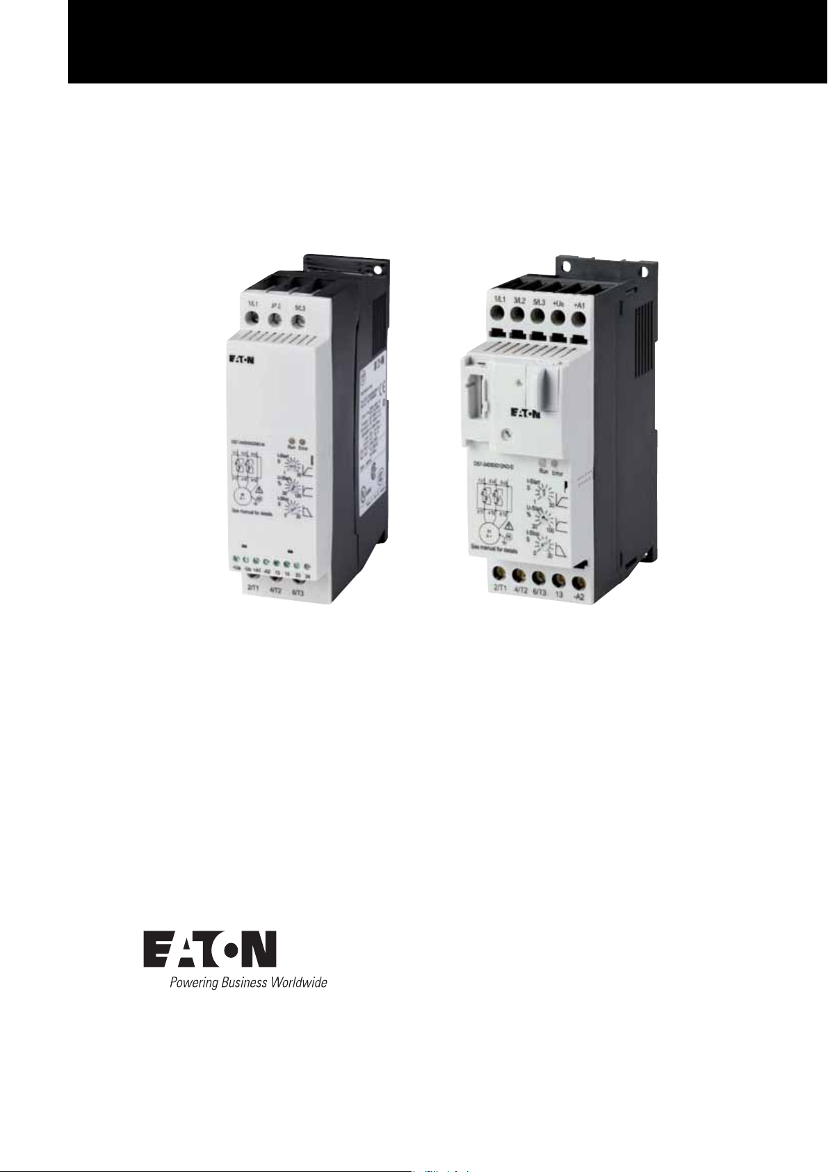
DS7
Soft starter
09/16 MN03901001Z-EN

All proprietary names and product designations are brand names or trademarks
registered to the relevant title holders.
Break-Down Service
Please call your local representative:
http://eaton.com/moeller/aftersales
or
Hotline After Sales Service:
+49 (0) 180 5 223822 (de, en)
AfterSalesEGBonn@eaton.com
Original operating manual
The German-language edition of this document is the original operating manual.
Translation of the original operating manual
All editions of this document other than those in German language are translations of
the original operating manual.
st
1
published 2010, edition date 07/10
nd
2
edition 2011, edition date 03/11
rd
3
edition 2011, edition date 06/11
th
4
edition 2011, edition date 11/11
th
5
edition 2012, edition date 07/12
th
6
edition 2013, edition date 09/13
th
7
edition 2016, edition date 09/16
See revision protocol in the “About this manual“ chapter
© 2010 by Eaton Industries GmbH, 53105 Bonn
Authors: Rainer Günzel, Jörg Randermann, Philipp Hergarten, Mustafa Akel
Redaction: René Wiegand
All rights reserved, also for the translation.
No part of this manual may be reproduced, stored in a retrieval system, or
transmitted in any form or by any means, electronic, mechanical, photocopying,
micro-filming, recording or otherwise, without the prior written permission of
Eaton Industries GmbH, Bonn.
Subject to alteration.

Danger!
Dangerous electrical voltage!
Before commencing the installation
• Disconnect the power supply of the device.
• Ensure that devices cannot be accidentally retriggered.
• Verify isolation from the supply.
• Ground and short-circuit.
• Cover or enclose neighbouring units that are live.
• Follow the engineering instructions (IL) of the device
concerned.
• Only suitably qualified personnel in accordance with
EN 50110-1/-2 (VDE 0105 Part 100) may work on this device/
system.
• Before installation and before touching the device ensure
that you are free of electrostatic charge.
• The functional earth (FE) must be connected to the
protective earth (PE) or to the potential equalizing.
The system installer is responsible for implementing this
connection.
• Connecting cables and signal lines should be installed so
that inductive or capacitive interference do not impair the
automation functions.
• Install automation devices and related operating elements
in such a way that they are well protected against unintentional operation.
• Suitable safety hardware and software measures should
be implemented for the I/O connection so that a cable or
wire breakage on the signal side does not result in
undefined states in the automation device.
• Ensure a reliable electrical isolation of the low voltage for
the 24 V supply. Only use power supply units complying
with IEC 60364-4-41 or HD 384.4.41 S2 (VDE 0100 part 410).
• Deviations of the mains voltage from the nominal value
must not exceed the tolerance limits given in the technical
data, otherwise this may cause malfunction and
dangerous operation.
• Emergency-Stop devices complying with IEC/EN 60204-1
must be effective in all operating modes of the automation
devices. Unlatching the emergency switching off devices
must not cause restart.
• Built-in devices for enclosures or cabinets must only be
run and operated in an installed state, desk-top devices or
portable devices only when the housing is closed.
• Measures should be taken to ensure the proper restart of
programs interrupted after a voltage dip or failure. This
Eaton Industries GmbH
should not cause dangerous operating states even for a
Safety instructions
short time. If necessary, emergency switching off devices
should be implemented.
• Wherever faults in the automation system may cause
damage to persons or property, external measures must
be implemented to ensure a safe operating state in the
event of a fault or malfunction (for example, by means of
separate limit switches, mechanical interlocks, etc.).
• During operation, and depending on their degree of
protection, variable frequency drives may have live,
uninsulated, moving, and/or rotating parts, as well as hot
surfaces.
• The impermissible removal of the required cover,
improper installation or incorrect operation of the motor or
variable frequency drive can cause the failure of the
device and serious injury and/or material damage.
• Comply with all applicable national accident prevention
regulations (e.g. BGV A3) when working with energized
variable frequency drives.
• The electrical installation must be carried out in
accordance with the relevant regulations (e.g. with regard
to cable cross sections, fuses, PE).
• All transport, installation, commissioning and maintenance work must only be carried out by trained personnel
(observe IEC 60364, HD 384 or DIN VDE 0100 and national
accident prevention regulations).
• If applicable, systems in which variable frequency drives
are installed must be equipped with additional monitoring
and protective devices in accordance with the applicable
safety regulations, e.g., the German Equipment and
Product Safety Act, accident prevention regulations, etc.
Making changes to the variable frequency drives by using
the operating software is allowed.
• Keep all covers and doors closed during operation.
• When designing the machine, the user must incorporate
mechanisms and measures that limit the consequences of
a drive controller malfunction or failure (an increase in
motor speed or the motor’s sudden stop) so as to prevent
hazards to people and property, e.g.:
– Additional stand-alone devices for monitoring parame-
ters that are relevant to safety (speed, travel, end
positions, etc.)
– Electrical and non-electrical safety devices (interlocks
or mechanical locks) for mechanisms that protect the
entire system
– Due to the possibility of there being capacitors that are
still holding a charge, do not touch live device parts or
terminals immediately after disconnecting the variable
frequency drives from the supply voltage. Heed the
corresponding labels on the variable frequency drives
I

II

Contents
Contents
0 About this Manual ..................................................................... 5
0.1 List of revisions ............................................................................ 5
0.2 Further manuals for this device.................................................... 5
0.3 Sources ........................................................................................ 6
0.4 Target group................................................................................. 6
0.5 Writing conventions ..................................................................... 7
0.5.1 Hazard warnings of material damages ......................................... 7
0.5.2 Hazard warnings of personal injury .............................................. 7
0.5.3 Tips............................................................................................... 7
0.6 Abbreviations ............................................................................... 8
0.7 Mains supply voltages.................................................................. 8
0.8 Units of measurement ................................................................. 9
1 Device series DS7....................................................................... 11
1.1 Front View.................................................................................... 11
1.2 Features ...................................................................................... 11
1.3 System overview ......................................................................... 12
1.4 Description ................................................................................... 13
1.4.1 DS7-340…, DS7-342… ................................................................ 13
1.4.2 DS7-34D… ................................................................................... 14
1.5 Key to part numbers..................................................................... 15
1.6 Checking the Delivery .................................................................. 17
1.7 Technical data .............................................................................. 19
1.7.1 Assigned motor outputs............................................................... 19
1.7.2 General data ................................................................................. 21
1.7.3 Device version.............................................................................. 22
1.7.4 Permissible environmental conditions ......................................... 22
1.8 Intended use ................................................................................ 22
1.9 Maintenance and inspection ........................................................ 23
1.10 Storage......................................................................................... 24
1.11 Service and warranty.................................................................... 24
1.12 Disposal........................................................................................ 24
1.13 Selection criteria........................................................................... 25
1.14 Function ....................................................................................... 26
2 Engineering................................................................................. 33
2.1 Selection of devices ..................................................................... 33
2.2 EMC compliance .......................................................................... 34
2.3 Network configurations................................................................ 34
2.4 Power connection ........................................................................ 35
2.5 emergency switching off ............................................................. 36
2.6 Protection..................................................................................... 36
2.6.1 Type 1 coordination...................................................................... 36
2.6.2 Type 2 coordination...................................................................... 36
2.7 Residual current circuit-breaker (RCD) ......................................... 37
2.8 motor protection .......................................................................... 38
2.9 DS7-SWD and PKE motor-protective circuit-breakers.................. 39
2.10 Cables, contactors, line filters ...................................................... 40
DS7 Soft starter 09/16 MN03901001Z-EN www.eaton.com 1

Contents
2.11 Motor connection......................................................................... 41
2.11.1 Connection configurations (star/delta configuration).................... 41
2.11.2 Connection and phase sequence................................................. 42
2.11.3 Delta connection.......................................................................... 43
2.11.4 Actuation of resistive loads.......................................................... 44
2.11.5 Connection of AC motors ............................................................ 45
2.11.6 Long motor supply cables............................................................ 46
2.11.7 Parallel motor connection ............................................................ 46
2.11.8 Connecting motors ...................................................................... 47
2.11.9 Cascade circuit............................................................................. 48
2.11.10 Motors with power factor correction capacitor............................ 48
2.11.11 Bypass circuit............................................................................... 49
2.11.12 Bypass circuit for emergency operation ...................................... 49
2.11.13 Repair and maintenance switch................................................... 51
2.12 Loading conditions ....................................................................... 53
2.12.1 Overload capability (load to AC-53a) ............................................ 53
2.12.2 Conversion of the overload capability to lower overcurrents....... 53
2.12.3 Different overload current............................................................ 54
2.12.4 Configuration options of DS7....................................................... 56
2.13 Design with different load cycles................................................. 57
2.14 Overtemperature (Derating)......................................................... 57
2.15 Example of other load cycles ....................................................... 58
3 Installation.................................................................................. 61
3.1 Introduction.................................................................................. 61
3.2 Mounting positions ...................................................................... 61
3.3 Flush mounting in control panel................................................... 62
3.3.1 Increased cooling......................................................................... 63
3.3.2 Mounting instructions (BG 1 and BG 2) ....................................... 69
3.3.3 Mounting instructions (size 3 and 4)............................................ 74
3.4 Electrical Installation .................................................................... 77
3.4.1 Connection to power section....................................................... 78
3.4.2 Connection in control section ...................................................... 80
3.4.3 Connection to SmartWire-DT....................................................... 82
3.4.4 Functions of control signal terminals ........................................... 85
3.4.5 Control section power supply ...................................................... 86
3.4.6 Internal device voltages ............................................................... 86
3.4.7 Ground control voltage................................................................. 86
3.4.8 Relay contacts.............................................................................. 87
3.4.9 Relay contacts - connection examples......................................... 89
3.5 Block diagrams............................................................................. 90
3.6 Insulation test .............................................................................. 91
4 Operation.................................................................................... 93
4.1 Checklist for commissioning........................................................ 93
4.2 Commissioning ............................................................................ 95
4.3 Extended functionality ................................................................. 96
4.4 Potentiometer settings ................................................................ 98
4.4.1 How the potentiometers work..................................................... 98
4.4.2 Examples ..................................................................................... 102
2 DS7 Soft starter 09/16 MN03901001Z-EN www.eaton.com

Contents
4.5 Commissioning instructions......................................................... 104
4.6 Start the motor............................................................................. 105
4.7 Operation ..................................................................................... 105
4.8 LED indicators .............................................................................. 106
4.8.1 Operating state signals ................................................................ 109
4.8.2 Signals in DS7-34D…-D ............................................................... 110
4.8.3 Messages in the event of faults................................................... 111
4.8.4 Error messages ............................................................................ 112
5 Diagnostics ................................................................................. 115
5.1 Fault retrieval................................................................................ 115
5.1.1 Motor not starting ........................................................................ 115
5.1.2 Motor stops immediately after start completed .......................... 115
5.1.3 Motor running unevenly ............................................................... 115
5.1.4 Motor consuming too much current ............................................ 116
5.1.5 Connected motor overheating ..................................................... 116
5.2 Acknowledgment of error messages........................................... 116
6 Parameterization........................................................................ 117
6.1 Operating principles ..................................................................... 117
6.2 Default settings of the basic device............................................. 117
7 Connection examples ................................................................ 119
7.1 Size 1 (4 – 12 A) ........................................................................... 119
7.1.1 Connection without soft stop ramp ............................................. 119
7.1.2 Connection with soft stop ramp................................................... 120
7.1.3 Standard connection with upstream mains contactor and
soft stop ramp.............................................................................. 121
7.1.4 Simple change of rotation ............................................................ 122
7.1.5 Rotation direction reversal with soft stop ramp ........................... 123
7.1.6 Reversing the direction of rotation with MSC-R .......................... 124
7.1.7 Connection for ac motor .............................................................. 126
7.2 Size 2 (16 – 32 A) ......................................................................... 127
7.2.1 Connection without soft stop ramp ............................................. 127
7.2.2 Connection with soft stop ramp................................................... 128
7.2.3 Standard connection with upstream mains contactor and
soft stop ramp.............................................................................. 129
7.2.4 Rotation direction reversal with soft stop ramp ........................... 130
7.3 Size 3 and 4 (41 – 200 A).............................................................. 132
7.3.1 Connection without soft start ramp ............................................. 132
7.3.2 Connection with soft start ramp .................................................. 133
7.3.3 Standard connection with upstream mains contactor and
soft stop ramp.............................................................................. 134
7.3.4 Rotation direction reversal with soft stop ramp ........................... 135
7.3.5 Compact motor starter with maintenance switch........................ 137
7.3.6 DS7 soft starter and NZM circuit-breaker with emergency-stop
function to IEC/EN 60204 and VDE 0113 Part 1 .......................... 138
7.3.7 Bypass circuit for emergency operation....................................... 139
7.3.8 Starting several motors sequentially with a soft starter............... 141
DS7 Soft starter 09/16 MN03901001Z-EN www.eaton.com 3

Contents
8 SmartWire-DT ............................................................................ 145
8.1 Introduction.................................................................................. 145
8.2 Profiles for DS7-SWD .................................................................. 146
8.3 1-0-A switch................................................................................. 146
8.4 Abbreviations ............................................................................... 147
8.5 SmartWire-DT response time ...................................................... 147
8.6 Interoperability ............................................................................. 148
8.6.1 Gateways..................................................................................... 148
8.6.2 Fieldbus description files ............................................................. 148
8.6.3 SWD-Assist.................................................................................. 148
8.7 Part numbers ............................................................................... 149
8.8 Replacing soft starters................................................................. 149
8.9 Programming ............................................................................... 150
8.9.1 Introduction.................................................................................. 150
8.9.2 State diagrams ............................................................................. 150
8.9.3 Cyclic data.................................................................................... 159
8.9.4 Cyclic data via PROFIBUS-DP ...................................................... 185
8.9.5 acyclic data................................................................................... 185
8.9.6 Acyclic parameter channel for DS7-SWD soft starter.................. 198
8.9.7 Data types.................................................................................... 202
8.9.8 Acyclic data via PROFIBUS-DP: DS7 ........................................... 208
8.9.9 Acyclic data via PROFIBUS-DP: PKE............................................ 210
8.10 SmartWire-DT diagnostics ........................................................... 211
8.10.1 Basic SWD Diagnostics ............................................................... 211
8.10.2 Advanced SmartWire-DT diagnostics .......................................... 212
8.10.3 PROFIdrive diagnostics................................................................ 213
8.10.4 SmartWire-DT diagnostic LEDs ................................................... 214
9 Appendix.................................................................................... 215
9.1 Standards..................................................................................... 215
9.2 Applicable product standards and approvals................................ 215
9.3 Specific technical data ................................................................. 216
9.3.1 Power supply dependent data ..................................................... 216
9.3.2 Terminal capacity, control cables, actuating circuit...................... 217
9.3.3 Heat dissipation PV ...................................................................... 218
9.4 Conversion to other load cycles................................................... 219
9.5 accessories .................................................................................. 221
9.5.1 Protection, short-circuit rating...................................................... 221
9.5.2 Protection, overload relay, optional mains contactor ................... 223
9.5.3 system accessories ..................................................................... 224
9.5.4 Device fans .................................................................................. 227
9.5.5 SmartWire-DT .............................................................................. 227
9.6 Dimensions.................................................................................. 228
Index ........................................................................................... 233
4 DS7 Soft starter 09/16 MN03901001Z-EN www.eaton.com

0 About this Manual
0.1 List of revisions
Publication date Page Subject new modified deleted
09/16 96 Extended functionality ✓
09/13 Fully revised; firmware version V46 ✓
07/12 145ff. Chapter “SmartWire-DT” ✓
11/11 89 Size 2 (16 - 32 A) – Isolated relay contacts
06/11 All Complete revision ✓✓
04/11 56 Configuration options of DS7 ✓
07/10 Initial issue
0 About this Manual
0.1 List of revisions
This manual contains special information that you will need to connect a soft
starter correctly and configure it to your requirements using the parameters.
The details apply to the indicated hardware and software versions.
The manual describes all construction sizes of the DS7 series soft starters.
Differences and special characteristics of each rating level and construction
size are listed accordingly.
The following significant amendments have been introduced since previous
issues:
44 Actuation of resistive loads ✓
All Complete revision ✓
✓
Size 3 and 4 (41 - 200 A) – Isolated relay contacts
216 Power supply dependent data (further) ✓
19 Power values ✓
0.2 Further manuals for this device
Further information can be found in the following manuals:
On “Soft starter”
• “Design of soft starters” - MN03902001Z-EN
(previous description AWB8250-1346D)
On “SmartWire-DT”
• “SmartWire-DT The system” – MN05006002Z-EN
(previous designation AWB2723-1617en)
• “SmartWire-DT module” – MN05006001Z-EN
(previous designation AWB2723-1613en)
• “SmartWire-DT Gateways” – MN05013002Z-EN
(previous designation AWB2723-1612en)
• “XIOC signal modules” – MN05002002Z-EN
(previous designation AWB2725-1452en
DS7 Soft starter 09/16 MN03901001Z-EN www.eaton.com 5

0 About this Manual
0.3 Sources
0.3 Sources
0.4 Target group
→
[1] Profile Drive Technology, PROFIdrive Technical Specification for
PROFIBUS and PROFINET, Version 4.1, May 2006; Order No: 3.172
The content of the manual is written for engineers and electricians. A
specialist knowledge of electrical engineering is needed for commissioning.
More information on the devices described here can be found on
the Internet under:
http://www.eaton.eu/Europe/Electrical/ProductsServices/
AutomationControl/SwitchingProtectingDrivingMotors/SoftStarters/DS7/
as well as
http://www.eaton.de/EN/EatonDE/ProdukteundLoesungen/Electrical/
Kundensupport/DownloadCenter/index.htm
→ Customer support → Download Center – Documentation
In the Quick Search box, enter the document name
(MN03901001).
The chapter “SmartWire-DT” is intended for automation technicians and
engineers. Detailed knowledge of the field bus systems used is presumed.
In addition you should be familiar with the handling of the SmartWire-DT
system.
6 DS7 Soft starter 09/16 MN03901001Z-EN www.eaton.com
0.5 Writing conventions
Symbols used in this manual have the following meanings:
▶ Indicates instructions to be followed.
0.5.1 Hazard warnings of material damages
NOTICE
Warns about the possibility of material damage.
0.5.2 Hazard warnings of personal injury
CAUTION
0 About this Manual
0.5 Writing conventions
0.5.3 Tips
→
Warns of the possibility of hazardous situations that may
possibly cause slight injury.
WARNING
Warns of the possibility of hazardous situations that could result
in serious injury or even death.
DANGER
Warns of hazardous situations that result in serious injury or
death.
Indicates useful tips.
DS7 Soft starter 09/16 MN03901001Z-EN www.eaton.com 7

0 About this Manual
0.6 Abbreviations
0.6 Abbreviations
The following abbreviations are used in this manual:
Abbreviation Meaning
BG Construction size
DS
DS7-SWD
EMC
GND
LED
PDS
RCD
SmartWire-DT
TOR
t-Start
t-Stop
U-Start
UL
U
LN
+U
/-U
s
s
Default settings
DS7 soft starter with SmartWire-DT
(abbreviated designation for devices with part no. DS7-34D…)
Electromagnetic compatibility
Ground (0-V-potential)
Light Emitting Diode (LED)
Power Drive System (magnet system)
Residual Current Device (residual current circuit-breaker)
SmartWire-DT
Top of Ramp
Ramp time for start voltage
Ramp time for voltage reduction
Start voltage
Underwriters Laboratories
Mains voltage
Control voltage
0.7 Mains supply voltages
The rated operating voltages stated in the following table are based on the
standard values.
In ring networks (as found in Europe) the rated operating voltage at the
transfer point of the power supply companies is the same as the value in the
consumer networks (e.g. 230 V or 400 V).
In star networks (as found in North America), the rated operating voltage at
the transfer point of the utility companies is higher than in the consumer
network.
Example: 120 V → 115 V, 240 V → 230 V, 480 V → 460 V.
The wide tolerance range of the DS7 soft starters allows for voltage drops of
10% and a voltage drop of additional 4 %, as well as an excess voltage of
10 % that are permissible in consumer supply networks.
The rated mains voltage operational data is always based on mains
frequencies of 50/60 Hz (50 Hz - 5 % – 60 Hz +5 %).
8 DS7 Soft starter 09/16 MN03901001Z-EN www.eaton.com
0.8 Units of measurement
Designation
Length inch 1 in (’’) 25.4 mm 0.0394
Power horsepower 1HP=1.014PS 0.7457 kW 1.341
Moment of torque pound-force inches 1 lbf in 0.113 Nm 8.851
Temperature
Rotational speed Revolutions per minute 1rpm 1min
Weight pound 1lb 0.4536 kg 2.205
Flow rate cubic feed per minute 1cfm 1.698 m3/min 0.5889
0 About this Manual
0.8 Units of measurement
Every physical dimension included in this manual uses international metric
system units, otherwise known as SI (Système International d’Unités) units.
For the purpose of the equipment’s UL certification, some of these
dimensions are accompanied by their equivalents in imperial units.
Table 1: Unit conversion examples
US-American
designation
Fahrenheit 1°F (TF) -17.222 °C (TC) TF=TC×9/5+32
Imperial unit SI value Conversion value
-1
1
DS7 Soft starter 09/16 MN03901001Z-EN www.eaton.com 9

0 About this Manual
0.8 Units of measurement
10 DS7 Soft starter 09/16 MN03901001Z-EN www.eaton.com
1 Device series DS7
1.1 Front View
1 Device series DS7
1.1 Front View
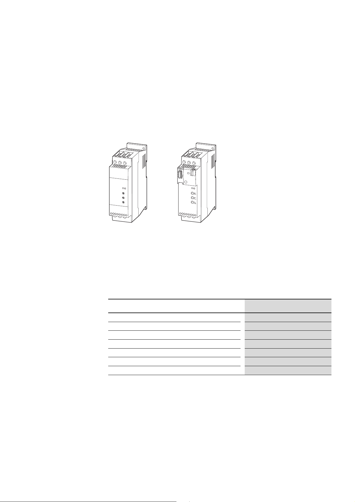
The following two devices are used as examples of the DS7 series:
• DS7-340SX032N0-N (left) – without SmartWire-DT interface
• DS7-34DSX032N0-D (right) with SmartWire-DT interface
1.2 Features
Figure 1: Front view of DS7 soft starter
Left: Without SmartWire-DT interface
Right: With SmartWire-DT interface
DS7 series soft starters comply with the IEC/EN 60947-4-2 product standard
and are provided with the following standard features:
Table 2: Features of the DS7 soft starters
Feature Instance
Compact design ✓
Adjustable start voltage
Separately adjustable ramp times for start and stop
Digital inputs
Relay output
Standard controller card and parameters over the entire performance range
Communication
✓
✓
✓ 1 (size 1), 2 (size 2, size 3, size 4)
✓ 1 (size 1), 2 (size 2, size 3, size 4)
✓
✓ via SmartWire-DT (with types DS7-34D…-D)
DS7 Soft starter 09/16 MN03901001Z-EN www.eaton.com 11
1 Device series DS7
S
W
D
4
-8
S
F
2
SWD
4-
8S
F
2
-
5
+ 1
5V
S
W
D4
-8
S
F
2
①
②
④
⑤
③
1.3 System over view
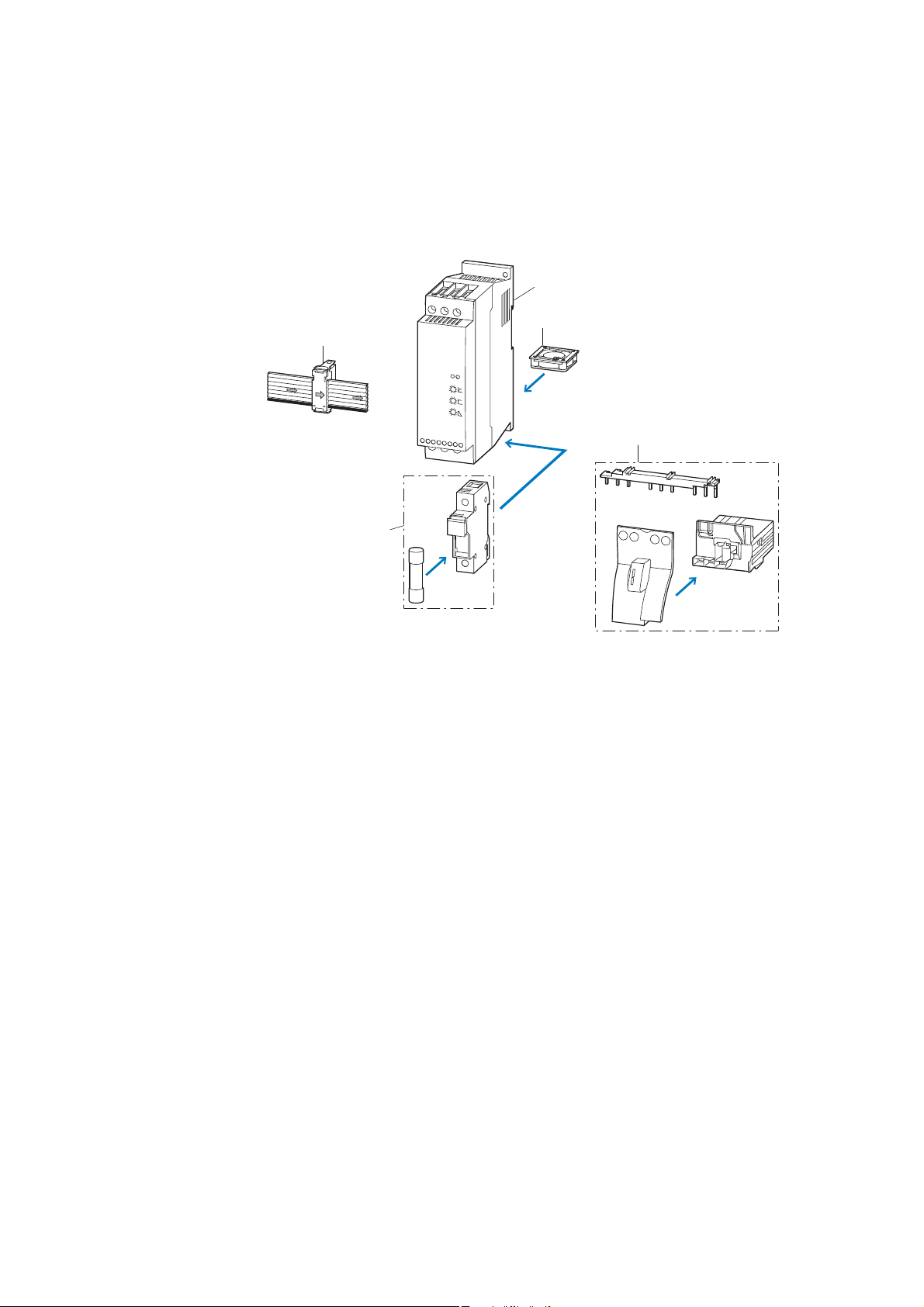
1.3 System overview
The following figure shows a DS7 soft starter together with (optional)
accessories.
Figure 2: System overview, DS7 soft starters
a DS7 soft starters
b Device fan (DS7-FAN-…)
c Communication System SmartWire-DT
d Mounting accessories
e Superfast semiconductor fuse and fuse base
12 DS7 Soft starter 09/16 MN03901001Z-EN www.eaton.com
1.4 Description
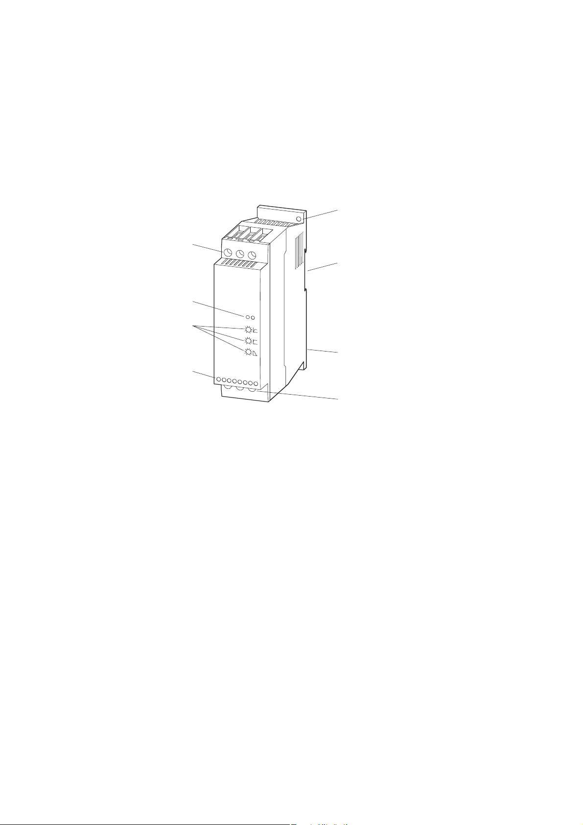
1.4.1 DS7-340…, DS7-342…
The following drawing shows a DS7 soft starter (without SmartWire-DT)
of size 2.
⑧
⑦
⑥
1 Device series DS7
1.4 Description
①
②
③
⑤
④
Figure 3: Description of the DS7-34…-N soft starter
a Fixing holes (screw fastening)
b Cutout for mounting on mounting rail (DIN EN 50022-35)
c Device fan (mounting space on back)
d Connection terminals of the power section, motor connection (2T1, 4T2, 6T3)
e Control signal terminals
f Potentiometer (U-Start, t-Start, t-Stop)
g LEDs (RUN, error)
h Connection terminals of the power section, mains voltage (1L1, 3L2, 3L3)
DS7 Soft starter 09/16 MN03901001Z-EN www.eaton.com 13
1 Device series DS7
①
②
④
⑤
⑥
⑦
⑧
⑫
③
⑨
⑩
⑪
1.4 Description
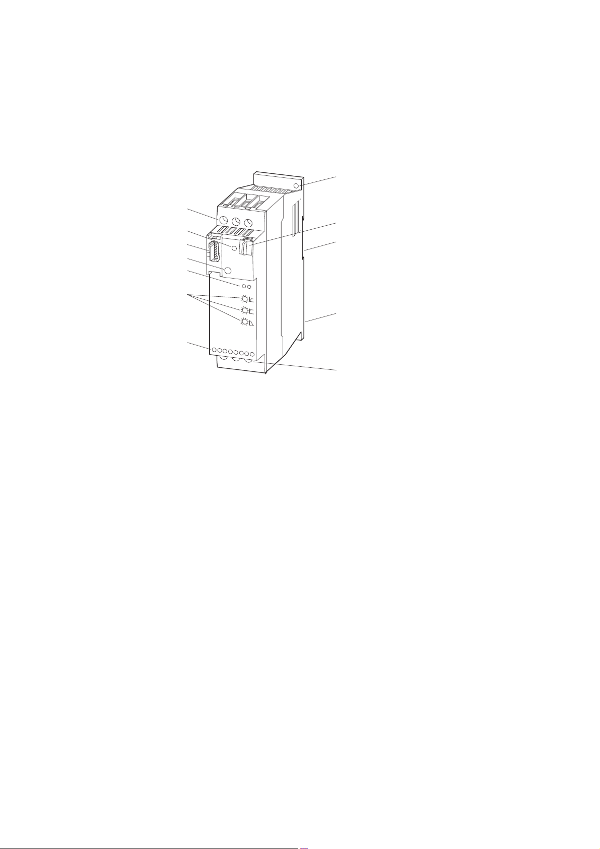
1.4.2 DS7-34D…
The following drawing shows a DS7-34D… soft starter with a SmartWire-DT
connection (hereafter referred to with the abbreviation DS7-SWD) of size 2.
Figure 4: Description of the DS7-34D…-D soft starter
a Fixing holes (screw fastening)
b Data interface for PKE32-COM
c Cutout for mounting on mounting rail (DIN EN 50022-35)
d Device fan (mounting space on rear)
e Connection terminals of the power section, motor connection (2T1, 4T2, 6T3)
f Control signal terminals
g Potentiometer (U-Start, t-Start, t-Stop)
h Light-emitting diodes (RUN, Error): DS7 diagnostic LEDs
i 1-0-A switch
j Connection for SmartWire-DT external device plug
k LED: SmartWire-DT diagnostic LED
l Connection terminals of the power section, mains voltage (1L1, 3L2, 3L3)
The SmartWire-DT external device plug with an adapted
→
SmartWire-DT ribbon cable is connected to the DS7-SWD soft
starter via connection ⑩.
For detailed instructions on how to use the SmartWire-DT
external device plug (SWD4-8SF2-5) with the 8-pin SmartWire-DT
cable, refer to the “Setting up SWD4-8SF2-5 external device
plugs” section in manual MN05006002Z-EN,
“SmartWire-DT - The System.”
→
SmartWire-DT diagnostic LED ⑪ shows the communication
status, the status of the DS7-SWD soft starter, and the
switching command via the SmartWire-DT system.
For more information on the SmartWire-DT diagnostic LED,
refer to → section 8.10.4, “SmartWire-DT diagnostic LEDs”,
page 214.
14 DS7 Soft starter 09/16 MN03901001Z-EN www.eaton.com
1.5 Key to part numbers
1 Device series DS7
1.5 Key to part numbers
The soft starters of the DS7 series are assigned part numbers according to
the following key to part numbers:
DS7 - 3 4 x SX yyy N 0 - z Explanation
Instance:
N = no option
D = SmartWire-DT
Degree of protection:
0 = IP00, IP20, NEMA 0
EMC filter
N = no filter
SX = Standard soft starter with internal bypass relay
Control voltage and Control signals:
D = 24 V DC
0 = 24 V AC/DC
2 = 120/230 V AC
Figure 5: DS7 key to part numbers
Rated operational current I
Examples: 004 = 4 A
012 = 12 A
200 = 200 A
Device version:
Mains supply voltage:
4 = 400 V (200 – 480 V)
Supply phases:
3 = three-phase incoming unit
Soft starter series:
Drives motor starter, Generation 7
:
e
DS7 Soft starter 09/16 MN03901001Z-EN www.eaton.com 15
1 Device series DS7
1.5 Key to part numbers
Example of key to part numbers
An example of the key to part numbers is shown below:
DS7 - 3 4 2 SX 024 N 0 - N Explanation
Instance:
N = no option
Degree of protection:
0 = IP00, IP20, NEMA 0
EMC filter
N = no filter
Rated operational current I
024
= 24 A
Device version:
SX = Standard soft starter with internal bypass relay
Control voltage and Control signals:
2 = 120/230 V AC
Mains supply voltage:
4 = 400 V (200 - 480 V)
Supply phases:
3 = three-phase incoming unit
Soft starter series:
Drives motor starter, Generation 7
:
e
16 DS7 Soft starter 09/16 MN03901001Z-EN www.eaton.com
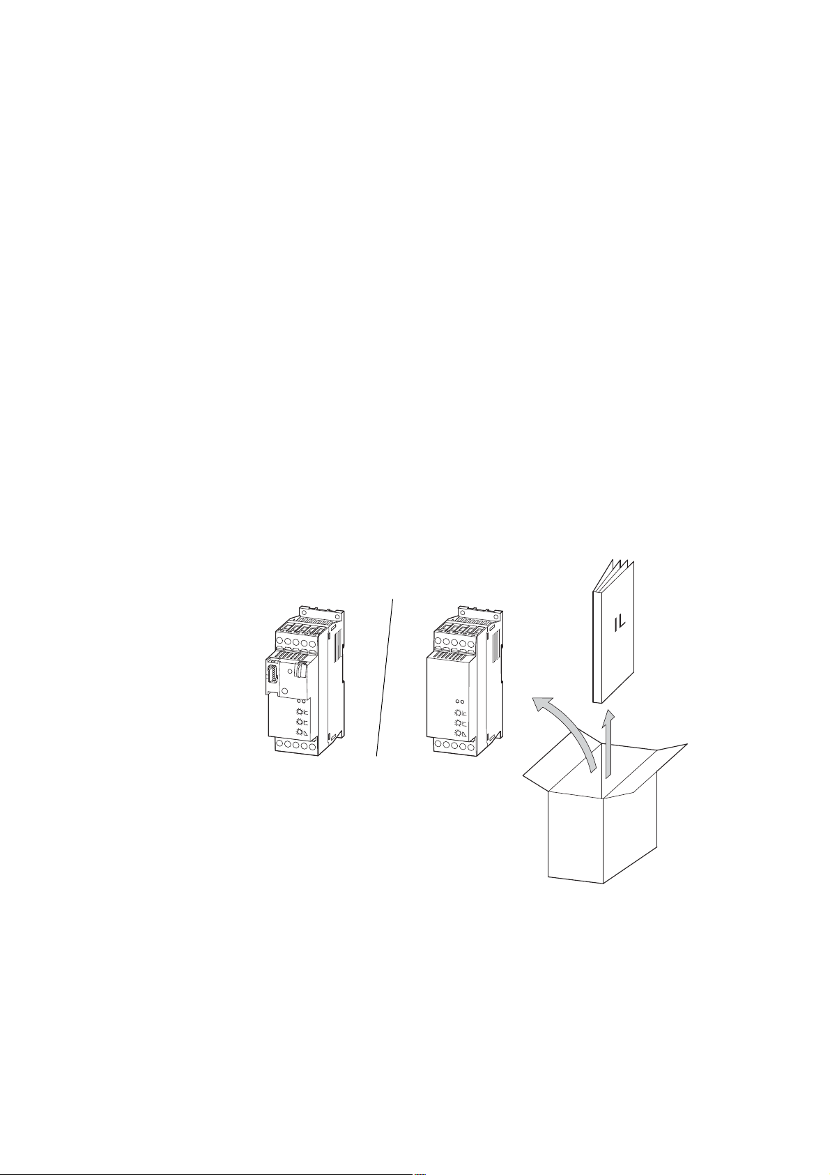
1.6 Checking the Delivery
1 Device series DS7
1.6 Checking the Delivery
→
The DS7 series soft starter are carefully packed and prepared for shipment.
These devices should only be shipped in their original packaging with suitable
transportation materials. Please take note of the labels and instructions on
the packaging, as well as of those meant for the unpacked device.
Open the packaging with adequate tools and inspect the contents
immediately after receipt in order to ensure that they are complete and
undamaged.
The packaging must contain the following parts:
• A soft starter from the DS7-34…-N or DS7-34…-D series
• an instructional leaflet IL (see table below).
If the delivered items are damaged, incomplete, or incorrect, please notify
the responsible sales office immediately.
Before opening the packaging go over the nameplate on the
packaging and check for whether the delivered soft starter is
the same part no. as the one you ordered.
Figure 6: Equipment supplied with DS7 soft starter
DS7 Soft starter 09/16 MN03901001Z-EN www.eaton.com 17
1 Device series DS7
1.6 Checking the Delivery
The part no. on the nameplate indicates the specific DS7 soft starter version
corresponding to the unit.
In the figure below, the following letters are used to provide the following
information:
• x: Control voltage U
• yyy: Rated operational current I
• z: Options / characteristics
Mains
U
LN
M
Motor
Figure 7: Nameplate and part no. position
The following table shows which instructional leaflets are meant for which
DS7 soft starter sizes:
or U
s
c
e
DS7-34 - x SX yyy N0- z
N = No Option
D = SmartWire-DT
I
e
U
s , Uc
0 = 24 V AC/DC
2 = 120/230 V AC
D = 24 V DC
≦ ULN:
U
e
200 - 480 VAC 3ph 50/60Hz
Table 3: Instruction leaflet for soft starter series DS7
Instruction leaflet Construction
IL03902003Z
(previous designation AWA8250-2541)
IL03902004Z
(previous designation AWA8250-2542)
IL03902005Z
(previous designation AWA8250-2543)
18 DS7 Soft starter 09/16 MN03901001Z-EN www.eaton.com
size
For device type Rated operational
BG1 DS7-34…SX004…
DS7-34…SX007…
DS7-34…SX009…
DS7-34…SX012…
BG2 DS7-34…SX016…
DS7-34…SX024…
DS7-34…SX032…
BG3 DS7-34…SX041…
DS7-34…SX055…
DS7-34…SX070…
DS7-34…SX081…
DS7-34…SX100…
BG4 DS7-34…SX135…
DS7-34…SX160…
DS7-34…SX200…
current I
004 = 4 A
007 = 7 A
009 = 9 A
012 = 12 A
016 = 16 A
024 = 24 A
032 = 32 A
041 = 41 A
055 = 55 A
070 = 70 A
081 = 81 A
100 = 100 A
135 = 135 A
160 = 160 A
200 = 200 A
e
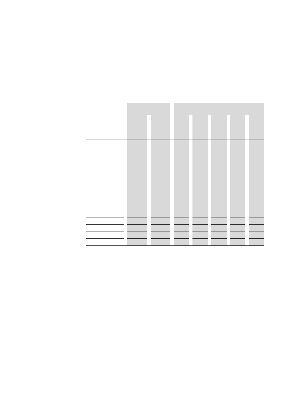
1.7 Technical data
1.7.1 Assigned motor outputs
The following motor outputs can be connected if using three-phase
asynchronous motors and a load suitable for soft starters.
Table 4: Assigned rated motor outputs for three-phase asynchronous motors
Part no. Soft starter’s rated
DS7-34xSX004N0-… 4 4.2 0.75 1.5 ¾ 1 2
DS7-34xSX007N0-…
DS7-34xSX009N0-…
DS7-34xSX012N0-…
DS7-34xSX016N0-…
DS7-34xSX024N0-…
DS7-34xSX032N0-…
DS7-34xSX041N0-…
DS7-34xSX055N0-…
DS7-34xSX070N0-…
DS7-34xSX081N0-…
DS7-34xSX100N0-…
DS7-34xSX135N0-…
DS7-34xSX160N0-…
DS7-34xSX200N0-…
1) Motor shaft output for normal four-pole internally and surface cooled three-phase asynchronous motors
2) IEC: Mains voltage = Motor voltage (at load) 230 V, 400 V
3) Reduced overload current acc. to UL 508C
4) Mains voltage 208 V / 240 V / 480 V ↔ motor voltage 200 V / 230 V / 460 V
operational current
2)
Ie (IEC)
A A kW kW HP HP HP
7 7.6 1.5 3 2 2 5
9 9.6 2.2 4 2 3 5
12 14 3 5.5 3 3 10
16 17.5 4 7.5 5 5 10
24 25.3 5.5 11 7½ 7½ 15
32 34 7.5 15 10 10 25
41 42 11 22 10 15 30
55 54 15 30 15 20 40
70 68 15 37 20 25 50
81 80 22 45 25 30 60
100 96 30 55 30 30 75
135 130 30 75 40 50 100
160 156 45 90 50 60 125
200 192 55 110 60 75 150
(1500 rpm at 50 Hz or 1800 rpm at 60 Hz)
Ie (UL)
1 Device series DS7
1.7 Technical data
Assigned motor output1) at
3), 4)
230 V 400 V 200 V 230 V 460 V
50 Hz 50 Hz 60 Hz 60 Hz 60 Hz
DS7 Soft starter 09/16 MN03901001Z-EN www.eaton.com 19
1 Device series DS7
1.7 Technical data
The motor outputs listed below can be connected when using single-phase
AC motors (asynchronous capacitor motors) and a load suitable for soft
starters within an industrial environment:
Table 5: Assigned rated motor outputs for AC motors
Part no. Soft starter’s rated
DS7-34xSX004N0-… 4 4.2 0.37 ¼ ⅓ ⅓
DS7-34xSX007N0-…
DS7-34xSX009N0-…
DS7-34xSX012N0-…
DS7-34xSX016N0-…
DS7-34xSX024N0-…
DS7-34xSX032N0-…
1) Motor shaft output for normal four-pole internal and surface-cooled AC motors
(1500 rpm at 50 Hz or 1800 rpm at 60 Hz)
2) IEC: Mains voltage = Motor voltage (at load) 230 V
3) Reduced overload current acc. to UL 508C
4) Mains voltage 208 V / 240 V ↔ motor voltage 200 V / 230 V
operational current
2)
Ie (IEC)
A A kW HP HP HP
7 7.6 0.75 ½ ½ ¾
9 9.6 1.1 ¾ 1 1
12 14 1.5 1 1½ 1½
16 17.5 2.2 2 2 2
24 25.3 3 3 3 3
32 34 4 5 5 5
Ie (UL)
Assigned motor output1) at
3), 4)
230 V 200 V 208 V 230 V
50 Hz 60 Hz 60 Hz 60 Hz
→
When using single-phase AC motors, the rated operational
current will depend on the system frequency and the capacitor
being used.
Example:
240 V, 50/60 Hz, 1.5/2.1 A
1300/1350 rpm, 5.0 μF CAP
20 DS7 Soft starter 09/16 MN03901001Z-EN www.eaton.com

1.7.2 General data
Table 6: General Technical Data
General
Product standard IEC/EN 60 947-4-2
Approvals, certificates
Mounting position
Degree of protection
Busbar tag shroud
Mechanical shock resistance
Vibration resistance to EN 60721-3-2
Power section
Rated operating voltage 200 - 480 V AC ±10 %
Mains frequency
Overload cycle to EN 60947-4-2
Minimum load current
Rated impulse withstand voltage
U
1.2/50 μs
imp
Rated insulation voltage U
Overvoltage category/pollution degree
Control section (inclusive SmartWire-DT)
Supply-/control voltage depending on variant
Mains frequency (with AC versions)
Rated impulse withstand voltage U
Rated insulation voltage U
Over voltage category
Soft start functions
Ramp times
Acceleration 1 - 30 s
Lag
Start voltage (= switch-off voltage)
Controlling and signalling
Control inputs depending on variant
Relay
LED
i
imp
i
CE, UL, CSA, CCC, Gost
vertical
IP20 for the front and operator control and operating
elements.
IP20 on all sides in size 1
IP00 on all sides in size 2, 3, 4
Finger- and back-of-hand proof
8 g/11 ms
2M2
50/60 Hz ±5 %
AC53a: 3-5: 75-10
0.5 A
4kV
500 V
II/2
24 V AC / 24 V DC (18 - 30 V ± 0 %)
120 - 230 V AC (98 - 264 V ± 0 %)
50/60 Hz ±5 %
2.5 kV
300 V
II
0 (= free run-down), 1 - 30 s
30 - 100 %
2 with size 1
4 with size 2
5 with size 3, size 4
depending on variant
1 with size 1 (non-isolated)
2 with size 2, 3, 4 (potential-free)
2 at DS7 without SWD (DS7-340…, DS7-342…)
3 at DS7 without SWD (DS7-34D…)
1 Device series DS7
1.7 Technical data
DS7 Soft starter 09/16 MN03901001Z-EN www.eaton.com 21
1 Device series DS7
TL
U
e
U
c
1.8 Intended use
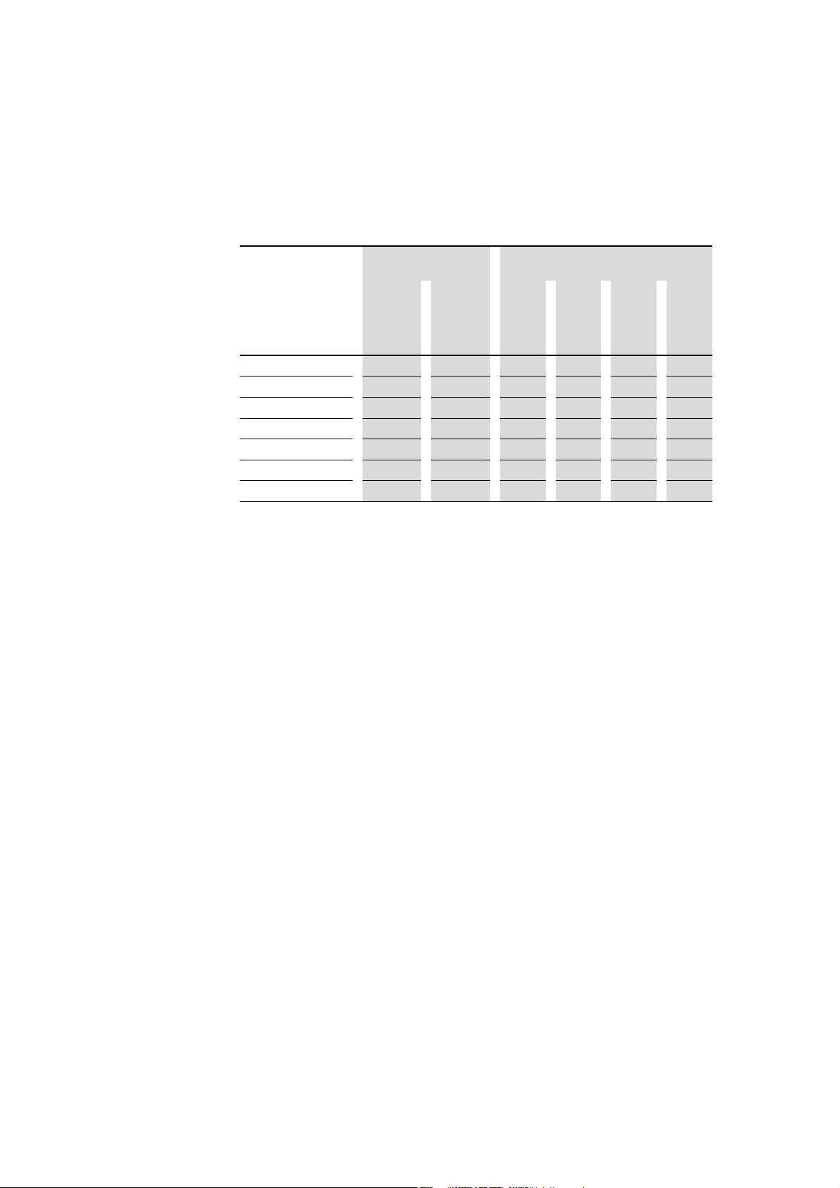
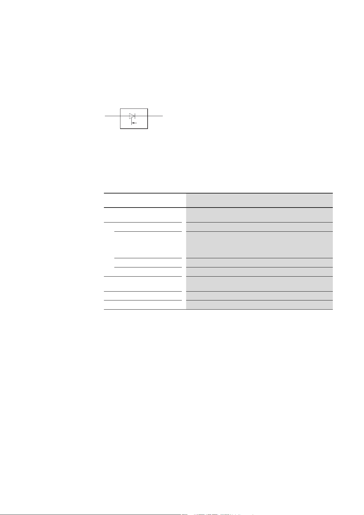
1.7.3 Device version
DS7 soft starters are classified in accordance with IEC 60947-4-2:2011,
Table 1
(Functional possibilities of semiconductor motor control devices).
The soft starters belonging to the DS7 series correspond to device version 1.
Figure 8: Semi-conductor – Motor – Controlgear
1.7.4 Permissible environmental conditions
The following shows the permissible values for the ambient influences on
soft starters of the DS7 series.
Table 7: Permissible environmental conditions
Property Value
1.8 Intended use
Installation altitude
Temperature
Operation -5 to +40 °C without current reduction,
Storage
Transport
Climatic proofing
Permissible humidity rating
Permissible pollution
1) Higher installation altitude upon request
1)
Up to 1000 m a.s.l.;
higher than this up to 2000 m with a current reduction of 1 % I
up to +60 °C with a current reduction of 1 % I
device fan is fitted
up to +60 °C with a current reduction of 2 % I
-25 - +60 °C continuous
-25 - +60 °C continuous
damp heat, cyclic, to DIN IEC Part 68 2-10
damp heat constant to DIN IEC 68 Part 2-3
Relative air humidity 85 %, non condensing
Pollution degree 2 to EN 60947-1
per Kelvin, if the DS7-FAN-032
e
per Kelvin without device fan
e
per 100 m
e
The devices of the DS7 series
• are not devices for household use, and are designed exclusively for use
in commercial applications,
• can be used in the described system configurations in the industrial
environment,
• are not machines in the sense of the EC Machinery Safety Directive,
• comply in a typical drive configuration with the requirements of the EU
EMC Directive, the EU Low Voltage Directive, as well as the specified
standards.
The soft starters of the DS7 series are electrical apparatus for installation in
the control panels of electrical systems or machines. They are designed for
the soft starting of single-phase or three-phase AC motors mounted in a
machine or for assembly with other machine or plant components.
22 DS7 Soft starter 09/16 MN03901001Z-EN www.eaton.com

1 Device series DS7
1.9 Maintenance and inspection
If installed in machines, the soft starters must not be commissioned until it
has been determined that the corresponding machines comply with the
safety requirements in Machinery Directive 2006/42/EC. Standard EN 60204
must be complied with within this context. Commissioning is only permitted
if the requirements of the EMC Directive (2014/30/EU) have been observed.
The soft starters of the DS7 series meet the requirements of the Low
Voltage Directive 2014/35/EU and the product standard EN 60947-4-2.
The user is responsible for ensuring that the use of the relevant machines,
as well as the corresponding applications, complies with all applicable EC
Directives. Any other usage constitutes improper use.
→
Observe the technical data and connection requirements. These are shown
on the rating plate of the soft starter as well as in this documentation.
1.9 Maintenance and inspection
DS7 soft starters will be maintenance-free provided that the corresponding
general rated operational data, as well as all specific technical data
(→ section 1.7, “Technical data”) for the relevant versions, is observed.
However, please note that external factors may have an impact on the
operation and lifespan of DS7 soft starters.
We therefore recommend that the devices are checked regularly and the
following maintenance measures are carried out at the specified intervals.
Table 8: Maintenance measures and maintenance intervals
Maintenance measures Maintenance interval
Clean cooling vents (cooling slits)
Check the fan function
Filter in the control panel doors
(see the manufacturer’s specifications)
Check the terminal’s (control signal terminals,
power terminals) tightening torques
Check connection terminals and all metallic surfaces for
corrosion
Motor cable
At the output of a DS7 soft starter (terminals U, V, W) you must
not
• connect any capacitive load (e.g. phase compensation
capacitors),
• do not connect any further soft starters (parallel connection
on output side).
please enquire
6 - 24 months (depending on the environment)
6 - 24 months (depending on the environment)
regularly
6 - 24 months; when stored, no more than 12 months later
(depending on the environment)
According to manufacturer specifications, no later than 5 years
DS7 soft starters are not designed in such a way as to allow for the
replacement or repair of their individual components or sub-assemblies.
DS7 Soft starter 09/16 MN03901001Z-EN www.eaton.com 23

1 Device series DS7
1.10 Storage
1.10 Storage
1.11 Service and warranty
If the DS7 soft starter is stored before use, suitable ambient conditions must
be ensured at the storage site:
• Storage temperature: -25 - +60 °C,
• Average relative humidity: < 85%; no condensation
In the unlikely event that you experience a problem with your DS7 soft
starter, please contact your local sales office.
When you call, have the following data ready:
• The exact part no. (see nameplate)
• the date of purchase,
• A detailed description of the problem related to the DS7 soft starter
If some of the information printed on the rating plate is not legible, please
state only the data which are clearly legible.
1.12 Disposal
Information concerning the guarantee can be found in the Terms and
Conditions Eaton Industries GmbH.
Hotline After Sales Service
+49 (0) 180 5 223822 (de, en)
AfterSalesEGBonn@eaton.com
The soft starters of the DS7 series can be disposed of as electronic scrap in
accordance with national regulations.
24 DS7 Soft starter 09/16 MN03901001Z-EN www.eaton.com

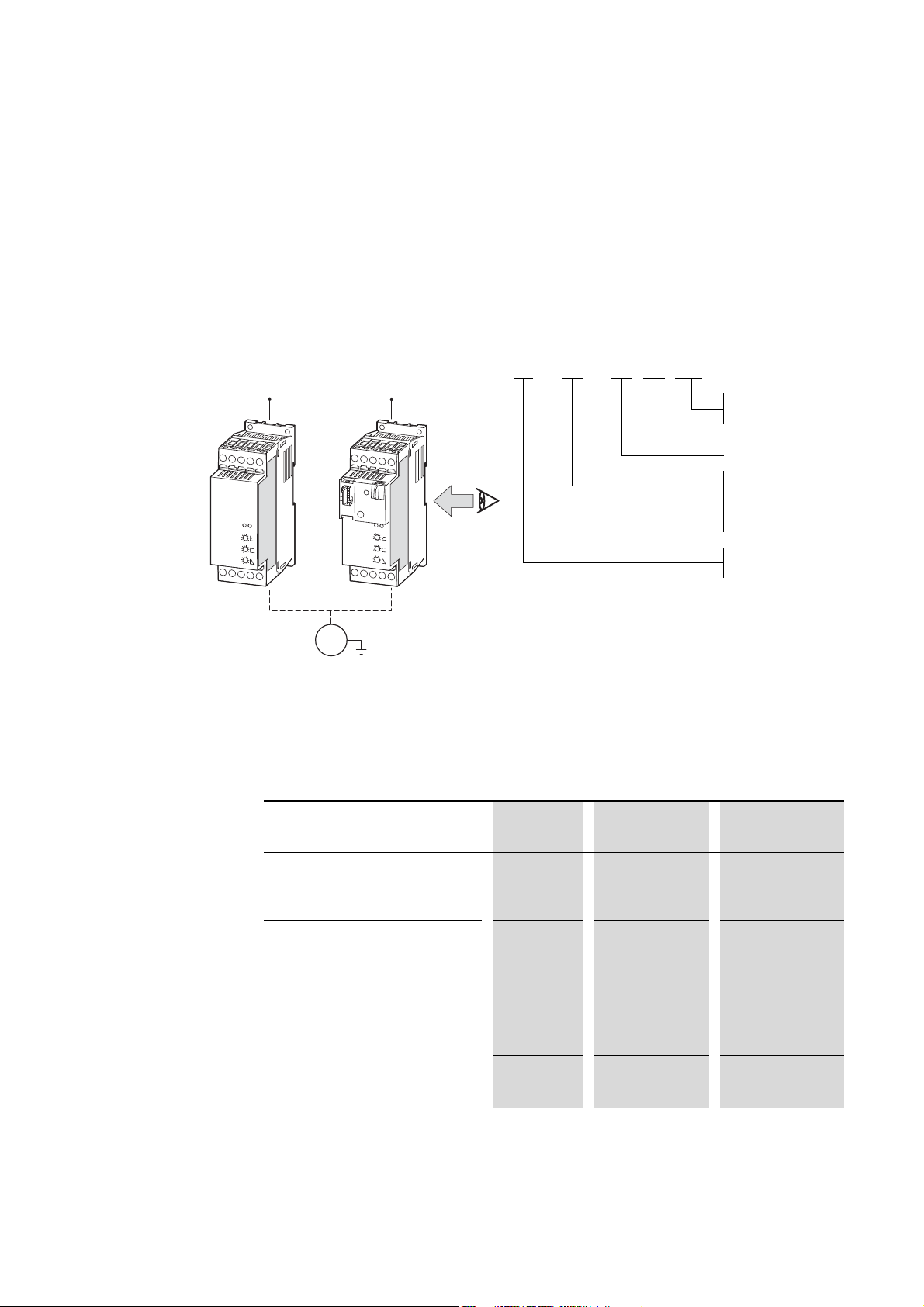
1.13 Selection criteria
1 Device series DS7
1.13 Selection criteria
The soft starter DS7 ③ is selected on the basis of the supply voltage ULN of
the supply network
motor
②. The circuit type (Δ
the supply voltage ①. The rated output current I
greater than/equal to the rated motor current.
① and the rated operational current of the assigned
/
) of the motor must be selected according to
of the soft starter must be
e
③
U, I, f
①
②
230 / 400 V ∆ /
1.1 kW
min
1430 50 Hz
4.6 / 2.6
A
cos ϕ
0.81
-1
Figure 9: Selection criteria
When selecting the drive, the following criteria must be taken into account:
• Type of motor (e.g.three-phase asynchronous motor)
• Mains voltage = rated operating voltage of the motor (e.g. 3 AC ~ 400 V),
• Rated motor current (recommended value, dependent on the circuit type
and the power supply),
• Load torque (quadratic, linear),
• Starting torque,
• Ambient air temperature (rated value +40 °C).
With heavy starting duty motors, the soft starter must be
→
overdimensioned in terms of its overload capacity.
In the case of single-phase AC motors (→ page 20), the
→
selection must be based on the mains voltage (= the motor’s
rated operating voltage) and the rated motor current for the
specific line frequency.
DS7 Soft starter 09/16 MN03901001Z-EN www.eaton.com 25
1 Device series DS7
①
②
③
④
⑤
M
3 ∼
1.14 Function
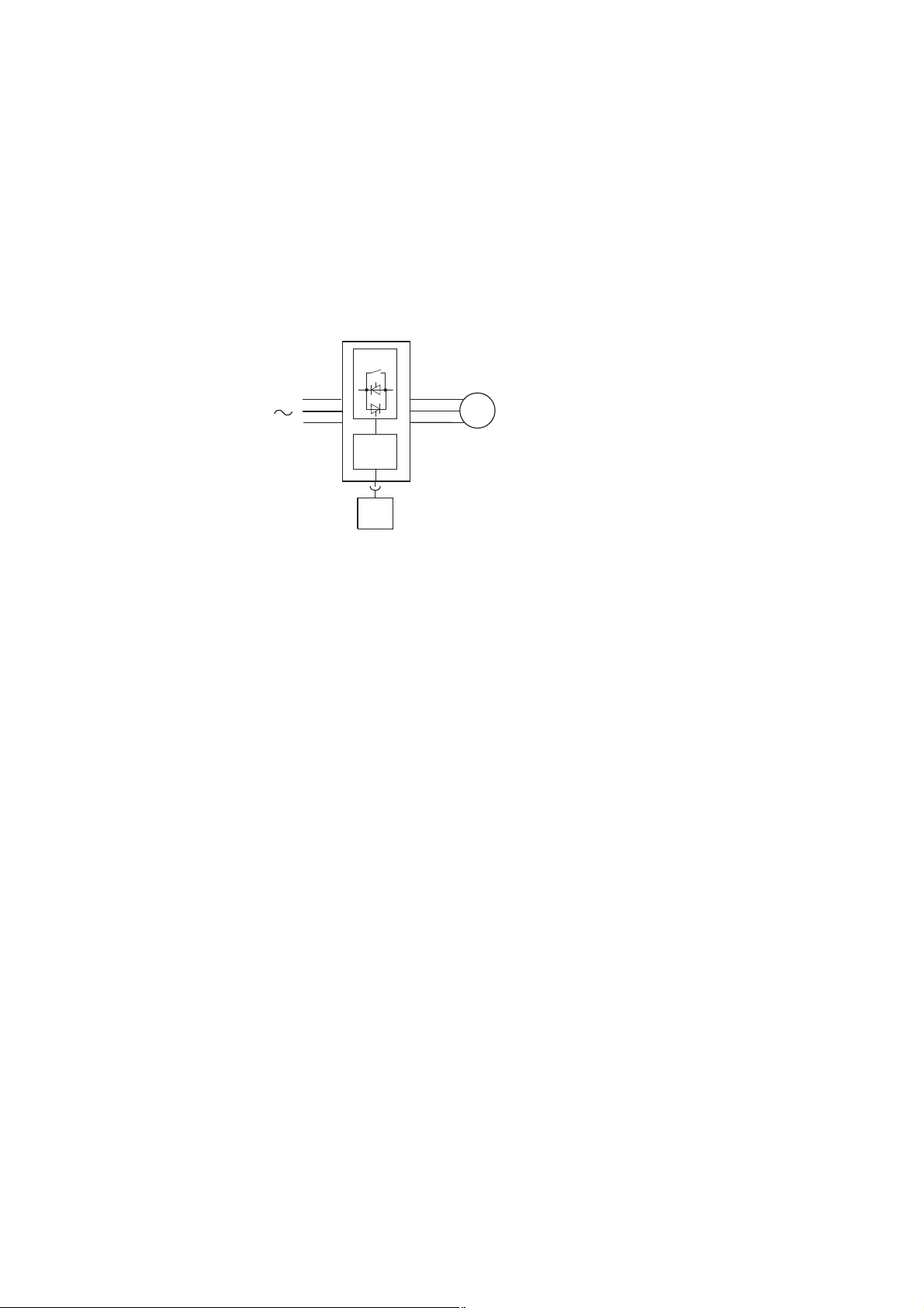
1.14 Function
DS7 soft starters use phase control for controlling the voltage of the supply
network smoothly from an adjustable start value up to 100 % of the rated
value U
. This voltage control enables the inrush current of a three-phase
LN
asynchronous motor to be limited and its starting torque to be considerably
reduced. This enables a smooth and jerk-free increase in torque, adjusted to
the load behavior of the machine.
Figure 10: Function chart
a Mains supply voltage U
b Antiparallel thyristors in two phases with bypass contact for controlling the motor voltage
c Output voltage U
ramp function at a constant line frequency
Output current I
Rated motor shaft output P
d Controller card for controlling the power section
This is used to initiate control commands and set the parameters.
e SmartWire-DT interface (optional) for configuring parameters and for control and monitoring
2N
3 × 200 V bis 3 × 480 V
LN
: three-phase, from an adjustable start voltage to 100% mains voltage with the use of a
2
: 4 - 200 A at a maximum ambient air temperature of +40 °C
: 1.5 - 110 kW with 400 or 3 - 150 HP with 480 V
2
The following limitations apply to single-phase AC motors:
→
① U
③ Output current I
Rated motor shaft output P
: 1 x 200 - 240 V
LN
: 4 - 32 A
2N
with 230 V: 0.37 - 4 kW or 1/3 - 5 HP
2
26 DS7 Soft starter 09/16 MN03901001Z-EN www.eaton.com
 Loading...