

Eaton DS-206S series, DS series, DSL series, DS-206 series, DS-416S series Instructions Manual
...
Instruction Booklet IB 33-790-1J
Effective November 2010
Supersedes IB 33-790-1I Dated 10/98
Instructions for Low Voltage Power
Circuit Breakers Types DS and DSL

Instruction Booklet IB 33-790-1J
Effective November 2010
This Page Left Intentionally Blank.
Instructions for Low Voltage Power
Circuit Breakers Types DS and DSL
EATON CORPORATION www.eaton.com

Instructions for Low Voltage Power
Circuit Breakers Types DS and DSL
Instruction Booklet IB 33-790-1J
Effective November 2010
Table of Contents
Description Page
Introduction . . . . . . . . . . . . . . . . . . . . . . . . . . . . . . . . . . . . . . . . . . . . . . . . . . . . . . . . . . . . . . . . . . . . . . . . . . 1
General Description . . . . . . . . . . . . . . . . . . . . . . . . . . . . . . . . . . . . . . . . . . . . . . . . . . . . . . . . . . . . . . . . . . . 2
Basic Breaker Assembly . . . . . . . . . . . . . . . . . . . . . . . . . . . . . . . . . . . . . . . . . . . . . . . . . . . . . . . . . . 2
Arc Chutes . . . . . . . . . . . . . . . . . . . . . . . . . . . . . . . . . . . . . . . . . . . . . . . . . . . . . . . . . . . . . . . . . . . . 2
Optional Components . . . . . . . . . . . . . . . . . . . . . . . . . . . . . . . . . . . . . . . . . . . . . . . . . . . . . . . . . . . . 2
Accessories. . . . . . . . . . . . . . . . . . . . . . . . . . . . . . . . . . . . . . . . . . . . . . . . . . . . . . . . . . . . . . . . . . . . 2
Special Circuit Breakers: DS-206S and DS-416S. . . . . . . . . . . . . . . . . . . . . . . . . . . . . . . . . . . . . . . 3
Safety Features . . . . . . . . . . . . . . . . . . . . . . . . . . . . . . . . . . . . . . . . . . . . . . . . . . . . . . . . . . . . . . . . . . . . . . . 4
Recommended Safety Practices . . . . . . . . . . . . . . . . . . . . . . . . . . . . . . . . . . . . . . . . . . . . . . . . . . . . . . . . . . 5
Section 1 -Receiving, Handling and Storing . . . . . . . . . . . . . . . . . . . . . . . . . . . . . . . . . . . . . . . . . . . . . . . . . 6
1.0 Receiving and Handling . . . . . . . . . . . . . . . . . . . . . . . . . . . . . . . . . . . . . . . . . . . . . . . . . . . . . . . 6
1.1 Storing . . . . . . . . . . . . . . . . . . . . . . . . . . . . . . . . . . . . . . . . .
1.2 Weights: Circuit Breakers a nd Fuse Tr ucks. . . . . . . . . . . . . . . . . . . . . . . . . . . . . . . . . . . . . . . . 6
Section 2 -First Removal of Breaker from Compartment . . . . . . . . . . . . . . . . . . . . . . . . . . . . . . . . . . . . . . . . 7
2.0 General. . . . . . . . . . . . . . . . . . . . . . . . . . . . . . . . . . . . . . . . . . . . . . . . . . . . . . . . . . . . . . . . . . . . 7
2.1 Setting the Rails in Front of the Compartment . . . . . . . . . . . . . . . . . . . . . . . . . . . . . . . . . . . . 7
2.2 Removing Shipping Brace . . . . . . . . . . . . . . . . . . . . . . . . . . . . . . . . . . . . . . . . . . . . . . . . . . . . . 7
2.3 Lifting the Breaker . . . . . . . . . . . . . . . . . . . . . . . . . . . . . . . . . . . . . . . . . . . . . . . . . . . . . . . . . . . 8
. . . . . . . . . . . . . . . . . . . . . . . . . . . 6
Section 3 -Preliminary Examination of Circuit Breaker . . . . . . . . . . . . . . . . . . . . . . . . . . . . . . . . . . . . . . . . . 9
3.0 General. . . . . . . . . . . . . . . . . . . . . . . . . . . . . . . . . . . . . . . . . . . . . . . . . . . . . . . . . . . . . . . . . . . . 9
3.1 Independent Manual and Power-operated Breakers . . . . . . . . . . . . . . . . . . . . . . . . . . . . . . . . . 12
3.1.1 Closing Facilities . . . . . . . . . . . . . . . . . . . . . . . . . . . . . . . . . . . . . . . . . . . . . . . . . . . . . . . . . . . . 12
3.1.2 Tripping Facilities .
3.2 Levering Device . . . . . . . . . . . . . . . . . . . . . . . . . . . . . . . . . . . . . . . . . . . . . . . . . . . . . . . . . . . . . 12
Section 4 -Basic Operating Instructions. . . . . . . . . . . . . . . . . . . . . . . . . . . . . . . . . . . . . . . . . . . . . . . . . . . . . 13
4.0 General. . . . . . . . . . . . . . . . . . . . . . . . . . . . . . . . . . . . . . . . . . . . . . . . . . . . . . . . . . . . . . . . . . . . 13
4.1 Levering Device . . . . . . . . . . . . . . . . . . . . . . . . . . . . . . . . . . . . . . . . . . . . . . . . . . . . . . . . . . . . . 13
4.2 Charge the Closing Springs . . . . . . . . . . . . . . . . . . . . . . . . . . . . . . . . . . . . . . . . . . . . . . . . . . . 13
4.3 Close the Breaker . . . . . . . . . . . . . . . . . . . . . . . . . . . . . . . . . . . . . . . . . . . . . . . . . . . . . . . . . . . 14
4.4 Open the Breaker . . . . . . . . . . . . . . . . . . . . . . . . . . . . . . . . . . . . . . . . . . . . . . . . . . . . . . . . . . . 14
4.5 Place the Breaker in the Tes t Position . . . . . . . . . . . . . . . . . . . . . . . . . . . . . . . . . . . . . . . . . . . 15
4.6 Place the Breaker in the Connect Position . . . . . . . . . . . . . . . . . . . . . . . . . . . . . . . . . . . . . . . 15
4.7 Remove the Breaker for Final Inspection . . . . . . . . . . . . . . . . . . . . . . . . . . . . . . . . . . . . . . . . . 15
4.8 Final Inspection . . . . . . . . . . . . . . . . . . . . . . . . . . . . . . . . . . . . . . . . . . . . . . . . . . . . . . . . . . . .
4.9 Amptector Trip Settings . . . . . . . . . . . . . . . . . . . . . . . . . . . . . . . . . . . . . . . . . . . . . . . . . . . . . . . 15
4.10 Place the Breaker in S ervice . . . . . . . . . . . . . . . . . . . . . . . . . . . . . . . . . . . . . . . . . . . . . . . . . . . 15
Section 5 -Description and Explanation of Operation . . . . . . . . . . . . . . . . . . . . . . . . . . . . . . . . . . . . . . . . . . 16
5.0 General. . . . . . . . . . . . . . . . . . . . . . . . . . . . . . . . . . . . . . . . . . . . . . . . . . . . . . . . . . . . . . . . . . . . 16
5.1 The Operating Mechanism a nd How It Works . . . . . . . . . . . . . . . . . . . . . . . . . . . . . . . . . . . . . . 16
5.1.1 Power-Operated Mechanism . . . . . . . . . . . . . . . . . . . . . . . . . . . . . . . . . . . . . . . . . . . . . . . . . . . 17
5.1.2 Explanation of Spring-Charging Mechanism for Power-operated Breakers . . . . . . . . . . . . . . . 17
5.1.2.1 Power Operation . . . . . . . . . . . . . . . . . . . . . . . . . . . . . . . . . . . . . . . . . . . . . . . . . . . . . . . . . . . . 18
5.1.3 Manual-operated Mechanisms . . . . . . . . . . . . . . . . . . . . . . . . . . . . . . . . . . . . . . . . . . . . . . . .
5.1.4 Explanation of Spring-charging Mechanism for Manually-o perated Breakers . . . . . . . . . . . .
5.1.5 Circuit Breaker Closing Mechanism . . . . . . . . . . . . . . . . . . . . . . . . . . . . . . . . . . . . . . . . . . . .
5.1.6 Circuit Breaker Tr ipping or Opening Mechanism . . . . . . . . . . . . . . . . . . . . . . . . . . . . . . . . . . . . 27
. . . . . . . . . . . . . . . . . . . . . . . . . . . . . . . . . . . . . . . . . . . . . . . . . . . . . . . . . . . 12
. 15
24
. 24
26
EATON CORPORATION www.eaton.com
i

Instruction Booklet IB 33-790-1J
Effective November 2010
Instructions for Low Voltage Power
Circuit Breakers Types DS and DSL
Description Page
5.1.6.1 Miscellaneous Details . . . . . . . . . . . . . . . . . . . . . . . . . . . . . . . . . . . . . . . . . . . . . . . . . . . . . . . . 28
5.1.7 Mechanical Interlocking, Description, and Explanation of Operation . . . . . . . . . . . . . . . . . . . . . 30
5.1.7.1 The REMOVE Position . . . . . . . . . . . . . . . . . . . . . . . . . . . . . . . . . . . . . . . . . . . . . . . . . . . . . . . . 31
5.1.7.2 The DISCONNECT Position . . . . . . . . . . . . . . . . . . . . . . . . . . . . . . . . . . . . . . . . . . . . . . . . . . . 31
5.1.7.3 The TEST Position . . . . . . . . . . . . . . . . . . . . . . . . . . . . . . . . . . . . . . . . . . . . . . . . . . . . . . . . . . . 31
5.1.7.4 The CONNECT Position . . . . . . . . . . . . . . . . . . . . . . . . . . . . . . . . . . . . . . . . . . . . . . . . . . . . . . 32
5.1.8 Detailed Explanation of Mechanical Interlock System . . . . . . . . . . . . . . . . . . . . . . . . . . . . . . . . 32
5.1.8.1 Spring Discharge Interlock . . . . . . . . . . . . . . . . . . . . . . . . . . . . . . . . . . . . . . . . . . . . . . . . . . . . . 33
5.1.8.2 Connected Breaker Manual Close Interlock . . . . . . . . . . . . . . . . . . . . . . . . . . . . . . . . . . . . . . . . 35
5.1.8.3 Breaker Equipped for Electric Lockout . . . . . . . . . . . . . . . . . . . . . . . . . . . . . . . . . . . . . . . . . . . . 36
5.1.8.4 Closed Breaker Interlock . . . . . . . . . . . . . . . . . . . . . . . . . . . . . . . . . . . . . . . . . . . . . . . . . . . . . . 37
5.1.8.5 Padlocking Provision . . . . . . . . . . . . . . . . . . . . . . . . . . . . . . . . . . . . . . . . . . . . . . . . . . . . . . . . . 37
Section 6 -Circuit Breaker Pole Units, Description and Operation . . . . . . . . . . . . . . . . . . . . . . . . . . . . . . . .
38
6.0 General . . . . . . . . . . . . . . . . . . . . . . . . . . . . . . . . . . . . . . . . . . . . . . . . . . . . . . . . . . . . . . . . . . . . 38
6.1 Moving Contact Sub-assemblies. . . . . . . . . . . . . . . . . . . . . . . . . . . . . . . . . . . . . . . . . . . . . . . .
6.2 Stationary Contact Sub-assemblies . . . . . . . . . . . . . . . . . . . . . . . . . . . . . . . . . . . . . . . . . . . . .
38
40
Section 7 -Arc Chute . . . . . . . . . . . . . . . . . . . . . . . . . . . . . . . . . . . . . . . . . . . . . . . . . . . . . . . . . . . . . . . . . . . 53
7.0 General . . . . . . . . . . . . . . . . . . . . . . . . . . . . . . . . . . . . . . . . . . . . . . . . . . . . . . . . . . . . . . . . . . . . 53
Section 8 -Circuit Breaker Automatic Tr ipping System. . . . . . . . . . . . . . . . . . . . . . . . . . . . . . . . . . . . . . . . . . 55
8.0 General . . . . . . . . . . . . . . . . . . . . . . . . . . . . . . . . . . . . . . . . . . . . . . . . . . . . . . . . . . . . . . . . . . . . 55
8.1 The Amptector II-A Tr ip Unit . . . . . . . . . . . . . . . . . . . . . . . . .
. . . . . . . . . . . . . . . . . . . . . . . . . . . 56
8.2 The Amptector I-A Tr ip Unit . . . . . . . . . . . . . . . . . . . . . . . . . . . . . . . . . . . . . . . . . . . . . . . . . . . . 57
8.2.1 Ground Fault Protection . . . . . . . . . . . . . . . . . . . . . . . . . . . . . . . . . . . . . . . . . . . . . . . . . . . . . . . 61
8.3 Making Current Release (Discriminator) . . . . . . . . . . . . . . . . . . . . . . . . . . . . . . . . . . . . . . . . . . . 61
8.4 Servicing of Amptector Tr ip Unit. . . . . . . . . . . . . . . . . . . . . . . . . . . . . . . . . . . . . . . . . . . . . . . . . 62
8.5 Actuator. . . . . . . . . . . . . . . . . . . . . . . . . . . . . . . . . . . . . . . . . . . . . . . . . . . . . . . . . . . . . . . . . . . . 62
8.6 Sensors . . . . . . . . . . . . . . . . . . . . . . . . . . . . . . . . . . . . . . . . . . . . . . . . . . . . . . . . . . . . . . . . . . . . 62
8.7 Optional Accessories . . . . . . . . . . . . . . . . . . . . . . . . . . . . . . . . . . . . . . . . . . . . . . . . . . . . . . . . . 63
8.7.1 Undervoltage Tr ip Attachment . . . . . . . . . . . . . . . . . . . . . . . . . . . . . . . . . . . . . . . . . . . . . . . . . . 64
8.7.2 Overcurrent Trip Switch . . . . . . . . . . . . . . . . . . . . . . . . . . . . . . . . . . . . . . . . . . . . . . . . . . . . . . . 64
8.7.3 High Load Switch (Available with Amptector l-A Only) . . . . . . . . . . . . . . . . . . . . . . . . . . . . . . . . 65
8.7.4 Latch Check Switch . .
. . . . . . . . . . . . . . . . . . . . . . . . . . . . . . . . . . . . . . . . . . . . . . . . . . . . . . . . 66
8.7.5 Auxiliary Switches . . . . . . . . . . . . . . . . . . . . . . . . . . . . . . . . . . . . . . . . . . . . . . . . . . . . . . . . . . . 66
8.7.6 Amptector Tr ip Unit Test Kit . . . . . . . . . . . . . . . . . . . . . . . . . . . . . . . . . . . . . . . . . . . . . . . . . . . . 67
8.7.6.1 General . . . . . . . . . . . . . . . . . . . . . . . . . . . . . . . . . . . . . . . . . . . . . . . . . . . . . . . . . . . . . . . . . . . 67
8.7.6.2 Description . . . . . . . . . . . . . . . . . . . . . . . . . . . . . . . . . . . . . . . . . . . . . . . . . . . . . . . . . . . . . . . . . 67
8.7.6.3 Operation . . . . . . . . . . . . . . . . . . . . . . . . . . . . . . . . . . . . . . . . . . . . . . . . . . . . . . . . . . . . . . . . . . 67
Section 9 -DSL Circuit Breakers and Fuse Trucks . . . . . . . . . . . . . . . . . . . . . . . . . . . . . . . . . . . . . . . . . . . . . 69
9.0 General . . . . . . . . . . . . . . . . . . . . . . . . . . . . . . . . . . . . . . . . . . . . . . . . . . . . . . . . . . . . . . . . . . . . 69
9.1 DSL Current Limiters. . . . . . . . . . . . . . . . . . . . . . . . . . . . . . . . . . . . . . . . . . . . . . . . . . . . . . . . . . 69
9.2 Blown Limiter Indicator . . . . . . . . . . . . . . . . . . . . . . . . . . . . . . . . . . . . . . . . . . . . . . . . . . . . . . . . 69
9.3 Fuse Tr ucks . . . . . . . . . . . . . . . . . . . . . . . . . . . . . . . . . . . . . . . . . . . . . . . . . . . . . . . . . . . . . . . . 70
9.3.1 Installing Fuse Tr ucks . . .
9.3.2 Replacing Fuses . . . . . . . . . . . . . . . . . . . . . . . . . . . . . . . . . . . . . . . . . . . . . . . . . . . . . . . . . . . . 71
9.3.3 Blown Fuse Indicator . . . . . . . . . . . . . . . . . . . . . . . . . . . . . . . . . . . . . . . . . . . . . . . . . . . . . . . . . 71
ii
EATON CORPORATION www.eaton.com
. . . . . . . . . . . . . . . . . . . . . . . . . . . . . . . . . . . . . . . . . . . . . . . . . . . . . 70

Instructions for Low Voltage Power
Circuit Breakers Types DS and DSL
Instruction Booklet IB 33-790-1J
Effective November 2010
Description Page
Section 10 -Fixed Breakers . . . . . . . . . . . . . . . . . . . . . . . . . . . . . . . . . . . . . . . . . . . . . . . . . . . . . . . . . . . . . . 73
10.0 General. . . . . . . . . . . . . . . . . . . . . . . . . . . . . . . . . . . . . . . . . . . . . . . . . . . . . . . . . . . . . . . . . . . . 73
Section 11 -Drawout Dummy Elements . . . . . . . . . . . . . . . . . . . . . . . . . . . . . . . . . . . . . . . . . . . . . . . . . . . . . 73
11.0 General. . . . . . . . . . . . . . . . . . . . . . . . . . . . . . . . . . . . . . . . . . . . . . . . . . . . . . . . . . . . . . . . . . . . 73
Section 12 -Inspection and Maintenance. . . . . . . . . . . . . . . . . . . . . . . . . . . . . . . . . . . . . . . . . . . . . . . . . . . . 74
12.0 General. . . . . . . . . . . . . . . . . . . . . . . . . . . . . . . . . . . . . . . . . . . . . . . . . . . . . . . . . . . . . . . . . . . . 74
12.1.1 When to Inspect . . . . . . . . . . . . . . . . . . . . . . . . . . . . . . . . . . . . . . . . . . . . . . . . . . . . . . . . . . . . . 75
12.1.2 What to Inspect . . . . . . . . . . . . . . . . . . . . . . . . . . . . . . . . . . . . . . . . . . . . . . . . . . . . . . . . . . . . . 76
12.1.2.1 DS-206, DS-206S, DS-416, DS-416S, and DS-420 . . . . . . . . . . . . . . . . . . . . . . . . . . . . . . . . . . 77
12.1.2.2 DS-632 and DS-840 . . . . . . . . . . . . . . . . . . . . . . . . . . . . . . . . . . . . . . . . . . . . . . . . . . . . . . . . . 78
12.1.3 Replacement of Contacts . . . . . . . . . . . . . . . . . . . . . . . . . . . . . . . . . . . . . . . . . . . . . . . . . . . .
. 78
12.1.3.1 DS-206 . . . . . . . . . . . . . . . . . . . . . . . . . . . . . . . . . . . . . . . . . . . . . . . . . . . . . . . . . . . . . . . . . . . 78
12.1.3.2 DS-416, DS-416S, DS-420, DS-632, and DS-840 . . . . . . . . . . . . . . . . . . . . . . . . . . . . . . . . . . . 78
12.1.4 Arc Chutes . . . . . . . . . . . . . . . . . . . . . . . . . . . . . . . . . . . . . . . . . . . . . . . . . . . . . . . . . . . . . . . . . 78
12.1.5 General Inspection . . . . . . . . . . . . . . . . . . . . . . . . . . . . . . . . . . . . . . . . . . . . . . . . . . . . . . . . . . 78
12.1.5.1 Power Operated Mechanisms . . . . . . . . . . . . . . . . . . . . . . . . . . . . . . . . . . . . . . . . . . . . . . . . . . 78
12.2 Factory Adjustments . . . . . . . . . . . . . . . . . . . . . . . . . . . . . . . . . . . . . . . . . . . . . . . . . . . . . . . . . . 79
12.2.1 Trip Latch Overlap . . . . . . . . . . . . . . . . . . . . . . . . . . . . . . . . . . . . . . . . . . . . . . . . . . . . . . . . . . . 80
12.2.2 Breaker Open Position Stop (DS-632 Only) . . . . . . . . . . . . . . . . . . . . . . . . . . . . . . . . . . . . . . . 80
12.2.3 Moving Contact Adjustment . . . . . . . . . . . . . . . . . . . . . . . . . . . . . . . . . . . . . . . . . . . . . . . . . . . . 80
12.2.4 Levering Mechanism . . . . . . . . . . . . . . . . . . . . . . . . . . . . . . . . . . . . . . . . . . . . . . . . . . . . . . . . . 80
12.3 Lubrication . . . . . . . . . . . . . . . . . . . . . . . . . . . . . . . . . . . . . . . . . . . . . . . . . . . . . . . . . . . . . . 81
12.3.1 Frequency . . . . . . . . . . . . . . . . . . . . . . . . . . . . . . . . . . .
. . .
. . . . . . . . . . . . . . . . . . . . . . . . . . . . . . 81
12.3.2 Location and Lubricant . . . . . . . . . . . . . . . . . . . . . . . . . . . . . . . . . . . . . . . . . . . . . . . . . . . . . . . 81
Section 13 -Renewal Parts . . . . . . . . . . . . . . . . . . . . . . . . . . . . . . . . . . . . . . . . . . . . . . . . . . . . . . . . . . . . . . 82
13.0 General. . . . . . . . . . . . . . . . . . . . . . . . . . . . . . . . . . . . . . . . . . . . . . . . . . . . . . . . . . . . . . . . . . . . 82
13.1 Identifying Parts for DS-416S and DS-206S . . . . . . . . . . . . . . . . . . . . . . . . . . . . . . . . . . . . . . . 82
13.1.1 DS-416S Parts . . . . . . . . . . . . . . . . . . . . . . . . . . . . . . . . . . . . . . . . . . . . . . . . . . . . . . . . . . . . . . 82
13.1.2 DS-206S Parts . . . . . . . . . . . . . . . . . . . . . . . . . . . . . . . . . . . . . . . . . . . . . . . . . . . . . . . . . . . . . . 82
List of Tables
1. Type DS Breaker Ratings . . . . . . . . . . . . . . . . . . . . . . . . . . . . . . . . . . . . . . . . . . . . . . . . . . . . . . . . . 1
2. DSL Breakers - Current Limiting Ty pe Breakers and Combinations. . . . . . . . . . . . . . . . . . . . . . . . . 2
3. Approximate Weights . . . . . . . . . . . . . . . . . . . . . . . . . . . . . . . . . . . . . . . . . . . . . . . . . . . . . . . . . . . . 6
4. Frame Size and Sensor Ratings . . . . . . . . . . . . . . . . . . . . . . . . . . . . . . . . . . . . . . . . . . . . . . . . . . . . 63
5. Sensor and Limiter Ratings. . . . . . . . . . . . . . . . . . . . . . . . . . . . . . . . . . . . . . . . . . . . . . . . . .
. . . . . . 69
EATON CORPORATION www.eaton.com
iii

Instruction Booklet IB 33-790-1J
Effective November 2010
Instructions for Low Voltage Power
Circuit Breakers Types DS and DSL
List of Illustrations
Figure Title Page
1 The Type DS Low Voltage Power Circuit Breaker Is Shipped Inside Its Own Compartment 7
2 Rails Are Stowed Away in the Compartment . . . . . . . . . . . . . . . . . . . . . . . . . . . . . . . . . . . . . 7
3 Levering Device Crank Handle Installed . . . . . . . . . . . . . . . . . . . . . . . . . . . . . . . . . . . . . . . . 8
4 Use of Breaker Lifting Adapter . . . . . . . . . . . . . . . . . . . . . . . . . . . . . . . . . . . . . . . . . . . . . . . . 8
5a View Showing Controls on the Panel (Pre 1988) . . . . . . . . . . . . . . . . . . . . . . . . . . . . . . . . . 9
5b View Showing Controls on the Panel (Post 1988) . . . . . . . . . . . . . . . . . . . . . . . . . . . . . . . . . 10
6a Left Side of Breaker with Levering Device Arm in REMOVE Position . . . . . . . . . . . . . . . . . . 11
6b DS 416 Breaker with Front Panel Removed . . . . . . . . . . . . . . . . . . . . . . . . . . . . . . . . . . . . . 11
7 Right Side Showing Levering Device Arm in TEST Position . . . . . . . . . . . . . . . . . . . . . . . . . 11
8 Rear View Showing Levering Device Arm in CONNECT Position . . . . . . . . . . . . . . . . . . . . . 11
9 Method Used to Press Trip Plate and Lower Shutter with One Hand,
Preparatory to Inserting Crank . . . . . . . . . . . . . . . . . . . . . . . . . . .
10 Front View of Mechanism (Manual Spring Charge Except for DS-632/840) . . . . . . . . . . . . . 16
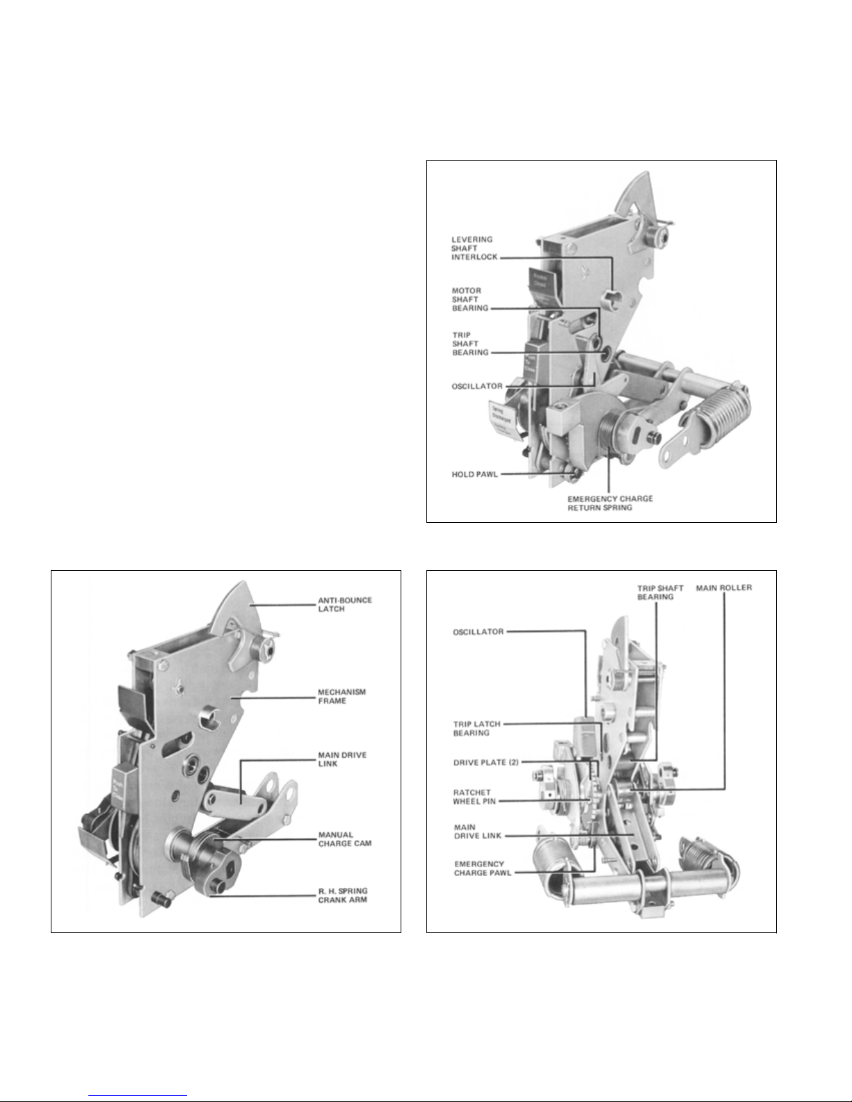
11 Front View of Mechanism (Power-Operated Spring Charge) . . . . . . . . . . . . . . . . . . . . . . . . . 16
12 Rear of Power-operated Mechanism . . . . . . . . . . . . . . . . . . . . . . . . . . . . . . . . . . . . . . . . . . 16
13 Rear View of Mechanism (Left Close Spring Removed) . . . . . . . . . . . . . . . . . . . . . . . . . . . . 17
14 Arrangement of the Principal Parts of a Power Operated Mechanism
The Close Spring is Shown in the Charged Position . . . . . . . . . . . . . . . . . . . . . . . . . . . . 18
15 Front View Showing Major Parts of the Crank Shaft Assembly
Some Parts are Omitted for Clarity . . . . . . . . . . . . . . . . . . . . . . . . . . . . . . . . . . . . . . . . . 19
16 Power-operated Spring-charge Details . . . . . . . . . . . . . . . . . . . . . . . . . . . . . . . . . . . . . . . . . 20
17 Crank Shaft Assembly of Power-operated Mechanism . . . . . . . . . . . . . . . . . . . . . . . . . . . . 21
18 Emergency Spring-charge on
19 Standard Schematic and Connection Diagrams for Power-Operated Breakers . . . . . . . . . . . 22
20 Principal Parts in a Manually Charged Spring Operated Mechanism . . . . . . . . . . . . . . . . . . 23
21 Spring-charging Mechanism on Manual Operated Breakers . . . . . . . . . . . . . . . . . . . . . . . . . 24
22 These Sketches Show the Four Basic Positions of Breaker and Linkage
with Enlarged View of Tr ip Shaft and Latch . . . . . . . . . . . . . . . . . . . . . . . . . . . . . . . . . . . 25
23 Shunt Trip Details Showing Tr ip Shaft Adjustment . . . . . . . . . . . . . . . . . . . . . . . . . . . . . . . . 265
24 Actuator . . . . . . . . . . . . . . . . . . . . . . . . . . . . . . . . . . . . . . . . . . . . . . . . . . . . . . . . . . . . . . . . . 27
25 DS-632 Breaker with Front Panel Removed . . . . . . . . . . . . . . . . . . . . . . . . . . . . . . . . . . . . . 28
26a Bottom View of Breaker Unit Showing Interference Interlock,
Motor Cut-off Switch and Other Details not Visible from Above . . . . . . . . . . . . . . . . . . . 29
26 Front View S
26 Rear View Showing the Seismic Positioner . . . . . . . . . . . . . . . . . . . . . . . . . . . . . . . . . . . . . . 29
27 Drawout Unit Position Indicator . . . . . . . . . . . . . . . . . . . . . . . . . . . . . . . . . . . . . . . . . . . . . .
28 Relation of Shutter, Tr ip Plate, and Tr ip Shaft . . . . . . . . . . . . . . . . . . . . . . . . . . . . . . . . . . . . 33
29 Relation of Shutter, Interlock Cam, and Levering Device Arms . . . . . . . . . . . . . . . . . . . . . . . 34
30 Close-Release Interlock to Discharge Springs on Levering Out of Compartment and
Conn. Position No Manual Close Interlock . . . . . . . . . . . . . . . . . . . . . . . . . . . . . . . . . . . . 35
31 Close Interlock to Prevent Efforts to Close a Breaker that Is Already Closed . . . . . . . . . . . . 36
32 Padlock Device - Locked Tr ip Free and Shutter Raised . . . . . . . . . . . . . . . . . . . . . . . . . . . . 37
33 Three-Pole Assembly of DS-206 Pole Units on Frame . . . . . . . . . . . . . . . . . . . . . . . . . . . . . 38
34 Three-Pole Assembly of DS-416 and DS-420 Pole Units on Frame . . . . . . . . .
35 Three-Pole Assembly of DS-632 Pole Units on Frame . . . . . . . . . . . . . . . . . . . . . . . . . . . . . 40
36 Three Pole Assembly of DS-840 Pole Units on Frame . . . . . . . . . . . . . . . . . . . . . . . . . . . . . 41
37 Type DS-206 Pole Unit Assembly - Front View . . . . . . . . . . . . . . . . . . . . . . . . . . . . . . . . . . . 42
38 Type DS-206 Pole Unit Assembly - Rear View . . . . . . . . . . . . . . . . . . . . . . . . . . . . . . . . . . . 43
howing Close Bar Guard . . . . . . . . . . . . . . . . . . . . . . . . . . . . . . . . . . . . . . . . . . 29
Power-operated Mechanism . . . . . . . . . . . . . . . . . . . . . . . . . 21
. . . . . . . . . . . . . . . . . 13
. . . . . . . . . . 39
30
iv
EATON CORPORATION www.eaton.com

Instructions for Low Voltage Power
Circuit Breakers Types DS and DSL
Instruction Booklet IB 33-790-1J
Effective November 2010
Figure Title Page
39 Type DS-416 Pole Unit Assembly - Front View . . . . . . . . . . . . . . . . . . . . . . . . . . . . . . . . . . . 44
40 Type DS-416 Pole Unit Assembly - Rear View . . . . . . . . . . . . . . . . . . . . . . . . . . . . . . . . . . . 44
41 Type DS-420 Pole Unit Assembly - Front View . . . . . . . . . . . . . . . . . . . . . . . . . . . . . . . . . . . 44
42 Type DS-420 Pole Unit Assembly - Rear View . . . . . . . . . . . . . . . . . . . . . . . . . . . . . . . . . . . 44
43 Type DS-632 Pole Unit Assembly - Front View . . . . . . . . . . . . . . . . . . . . . . . . . . . . . . . . . . . 45
44 Type DS-632 Pole Unit Assembly - Rear View . . . . . . . . . . . . . . . . . . . . . . . . . . . . . . . . . . . 45
45 Type DS-840 Pole Unit Assembly - Front View . . . . . . . . . . . . . . . . . . . . . . . . . . . . . . . . . . . 45
46 Type DS-840 Pole Unit Assembly - Rear View . . . . . . . . . . . . . . . . . . . . . . . . . . . . . . . . . . . 45
47 Moving and Stationary Contact Details DS-206 . . . . . . . . . . . . . . . . . . . . . . . . . . . . . . . . . . 46
48 Moving and Stationary Contact Details DS-416 . . . . . . . . . . .
. . . . . . . . . . . . . . . . . . . . . . . 47
49 Moving and Stationary Contact Details DS-420 . . . . . . . . . . . . . . . . . . . . . . . . . . . . . . . . . . 48
50 Moving Contact Details DS-632 . . . . . . . . . . . . . . . . . . . . . . . . . . . . . . . . . . . . . . . . . . . . . . 49
51 Stationary Contact Details DS-632 . . . . . . . . . . . . . . . . . . . . . . . . . . . . . . . . . . . . . . . . . . . . 50
52 Moving Contact Details DS-840 . . . . . . . . . . . . . . . . . . . . . . . . . . . . . . . . . . . . . . . . . . . . . . 51
53 Stationary Contact Details DS-840 . . . . . . . . . . . . . . . . . . . . . . . . . . . . . . . . . . . . . . . . . . . . 52
54 Breaker with Barrier Removed to Show Mounting of Arc Chutes . . . . . . . . . . . . . . . . . . . . . 53
55 DS-206 Arc Chute with Details . . . . . . . . . . . . . . . . . . . . . . . . . . . . . . . . . . . . . . . . . . . . . . . 53
56 DS-416/420 Arc Chute with Details . . . . . . . . . . . . . . . . . . . . . . . . . . . . . . . . . . . . . . . . . . . . 53
57 DS-632 Arc Chute with Details . . . . . . . . . . . . . . . . . . . . . . . . . . . . . . . . . . . . . . . . . . . . . . . 53
58 DS-840 Arc Chute with Details . . . . . . . . . . . . . . . . . . . . . . . . . . . . . . . . . . . . . . . . . . . . . . . 54
59 Schematic Illustration of Tr ipping System . . . . . . . . . . . . . . . . . . . . . . . . . . . . . . . . . . . . . . . 55
60 Standard Amptector II-A Sol
id-State Tr ip Unit . . . . . . . . . . . . . . . . . . . . . . . . . . . . . . . . . . . . 56
61 Amptector II-A Tr ip Unit with Front Cover Removed . . . . . . . . . . . . . . . . . . . . . . . . . . . . . . . 56
62 Optional Amptector I-A Solid-State Trip Unit . . . . . . . . . . . . . . . . . . . . . . . . . . . . . . . . . . . . . 57
63 Amptector I-A Tr ip Unit with Front Cover Removed . . . . . . . . . . . . . . . . . . . . . . . . . . . . . . . 58
64 Trip Actuator . . . . . . . . . . . . . . . . . . . . . . . . . . . . . . . . . . . . . . . . . . . . . . . . . . . . . . . . . . . . . 62
65 DS-840 Breaker with Front Panel Removed . . . . . . . . . . . . . . . . . . . . . . . . . . . . . . . . . . . . . 63
66 DS-840 Breaker Rear View Showing Sensors . . . . . . . . . . . . . . . . . . . . . . . . . . . . . . . . . . . 63
67 Undervoltage Tr ip Device . . . . . . . . . . . . . . . . . . . . . . . . . . . . . . . . . . . . . . . . . . . . . . . . . . . 64
68 Undervoltage Tr ip Device Operation . . . . . . . . . . . . . . . . . . . . . . . . . . . . . . . . . . . . . . . . . . . 64
69 Overcurrent Tr ip Switch . . . . . . . . . . . . . . . . . . . . . . . . . . . . . . . . . . . . . . . . . . . . . . . . . . . . . 65
70 Overcurrent Tr ip Switch Operation . . . . . . . . . . . . . . . . . . . . . . . . . . . . . . . . . . . . . . . . . . . . . 65
71 High Load Switch . . . . .
. . . . . . . . . . . . . . . . . . . . . . . . . . . . . . . . . . . . . . . . . . . . . . . . . . . . 65
72 Latch Check Switch . . . . . . . . . . . . . . . . . . . . . . . . . . . . . . . . . . . . . . . . . . . . . . . . . . . . . . . . 66
73 Latch Check Switch Operation . . . . . . . . . . . . . . . . . . . . . . . . . . . . . . . . . . . . . . . . . . . . . . . . 66
74 Auxiliary Switch Construction Details . . . . . . . . . . . . . . . . . . . . . . . . . . . . . . . . . . . . . . . . . . . 66
75 Amptector Trip Unit Test Kit (For Amptector I-A and II-A) . . . . . . . . . . . . . . . . . . . . . . . . . . . 67
76 Test Kit in Operation . . . . . . . . . . . . . . . . . . . . . . . . . . . . . . . . . . . . . . . . . . . . . . . . . . . . . . . 68
77 DSL-206 Breaker Side View . . . . . . . . . . . . . . . . . . . . . . . . . . . . . . . . . . . . . . . . . . . . . . . . . 69
78 DSL-206 Breaker Front View (DSL-416 Similar) . . . . . . . . . . . . . . . . . . . . . . . . . . . . . . . . . . 70
79 DSL-416 Breaker Side View . . . . . . . . . . . . . . . . . . . . . . . . . . . . . . . . . . . . . . . . . . . . . . . . . 70
80 Blown Limiter Indicator . . . . . . . . . . . . . . . . . . . . . . . . . . . . . . . . . . . . . . . . . . . . . . . . . . . . . . 71
81 DS-3200 Fuse Truck Front View . . . . . . . . . . . . . . . . . . . . . . . . . . . . . . . . . . . . . . . . . . . . . . 71
82 DS-3200 Fuse Truck with Front Cover Re
moved . . . . . . . . . . . . . . . . . . . . . . . . . . . . . . . . . 72
83 DS-4000 Fuse Truck Side View . . . . . . . . . . . . . . . . . . . . . . . . . . . . . . . . . . . . . . . . . . . . . . 72
84 Contacts and their Adjustment, DS-206 Breaker . . . . . . . . . . . . . . . . . . . . . . . . . . . . . . . . . . 74
85 Contacts and their Adjustment, DS-416/420 Breaker . . . . . . . . . . . . . . . . . . . . . . . . . . . . . . 75
EATON CORPORATION www.eaton.com
v

Instruction Booklet IB 33-790-1J
Effective November 2010
Instructions for Low Voltage Power
Circuit Breakers Types DS and DSL
Figure Title Page
86 Contacts and Their Adjustment, DS-632 Breaker . . . . . . . . . . . . . . . . . . . . . . . . . . . . . . . . . . 76
87 Contacts and Their Adjustment, DS-840 Breaker . . . . . . . . . . . . . . . . . . . . . . . . . . . . . . . . . . 77
88 Open Position Stop and Anti-rebound Latch . . . . . . . . . . . . . . . . . . . . . . . . . . . . . . . . . . . . . 78
89 Levering Mechanism . . . . . . . . . . . . . . . . . . . . . . . . . . . . . . . . . . . . . . . . . . . . . . . . . . . . . . . 79
90 Lubrication Points on Left Side of Mechanism . . . . . . . . . . . . . . . . . . . . . . . . . . . . . . . . . . . . 80
91 Lubrication Points on Right Side of Mechanism . . . . . . . . . . . . . . . . . . . . . . . . . . . . . . . . . . 81
vi
EATON CORPORATION www.eaton.com

Instructions for Low Voltage Power
Circuit Breakers Types DS and DSL
This instruction book is expressly intended to cover the installation, operation and maintenance
of Low Voltage Power Circuit Breakers, Types DS and DSL.
For application information, consult your nearest Eaton sales office, see Eaton
Descriptive Bulletin 32-850, or appropriate ANSI Standards.
Instruction Booklet IB 33-790-1J
Effective November 2010
PURPOSE
NOTE: This manual covers both Pre and Post 1988 versions of DS and DSL Low Voltage Power
Circuit Breakers. The two main differences are the front cover and the trip unit (Amptector
vs. Digitrip RMS) - see IL8700C39 supplied with the breaker for the Digitrip RMS trip unit details.
Except for the front cover and trip unit, all other sections in this manual apply to current production.
SAFETY
All Safety Codes, Safety Standards and/or Regulations as they may be applied to this type of
equipment must be strictly adhered to.
All possible contingencies which may arise during installation, operation, or maintenance, and all details and variations of this equipment do not
purport to be covered by these instructions. If further information is desired by purchaser regarding his particular installation, operation or
maintenance of his equipment, the local Eaton representative should be contacted.
EATON CORPORATION www.eaton.com
vii

Instruction Booklet IB 33-790-1J
Effective November 2010
Instructions for Low Voltage Power
Circuit Breakers Types DS and DSL
CAUTION
The circuit breakers described in this book were
designed and tested to operate within their nameplate
ratings. Operation outside of these ratings may cause
the equipment to fail, resulting in bodily injury and
property damage.
viii
EATON CORPORATION www.eaton.com
Instructions for Low Voltage Power
Circuit Breakers Types DS and DSL
Instruction Booklet IB 33-790-1J
Effective November 2010
Introduction
These instructions cover the description, operation and
maintenance of Eaton Type DS and Type DSL
Low Voltage AC Power Circuit Breakers and Type DS
Drawout Fuse Trucks. These breakers are usually supplied as part of low voltage metal enclosed switchgear of
the four-position drawout type. These instructions apply
only to the circuit breaker and its auxiliary drawout details
which have been designed as a completely integrated
drawout unit. Type DS Breakers (not DSL) may also be
supplied in a fixed mounted version. In this case the sections of this book referring to the levering device, position
interlocks, and spring discharge interlock will not apply.
The DS and DSL Circuit Breakers operate on the magnetic De-ion principle of interruption. In these br
eakers
the arc rises into a series of insulated steel plates. The
plates break the rising arc into a series of smaller arcs to
cool and extinguish them and funnel the heat to ambient
air.
Table 1 - Type DS Breaker Ratings
Interrupting Ratings, RMS Symmetrical Amperes
Breaker
Type
Frame Size,
Amp.
208-240V 480V 600V 208-240V 480V 600V
With Instantaneous Trip With Short Delay Trip
DS and DSL Breakers are available for application at voltages from 208 to 600 Vac; with continuous currents of 50
to 4000 amps; and with interrupting capabilities up to
200,000 amps. Refer to the breaker nameplate for the
complete rating information for any given breaker. Breakers conform to NEMA, ANSI, and IEEE standards.
TYPE DS AND DSL BREAKERS ARE PROTECTIVE
DEVICES. AS SUCH, THE Y ARE MAXIMUM CURRENT RATED DEVICES. THEREFORE, THE Y
SHOULD NOT UNDER ANY CIRCUMSTANCES BE
APPLIED OUTSIDE THE IR NAMEPLATE RATINGS.
OPERATION OUTSIDE OF THESE RATINGS MAY
CAUSE THE EQUIPMENT TO FAIL, RESULTING IN
BODIL
Y INJURY AND P
ROPERTY DAMAGE.
The available DS and DSL Breakers and their rated performance capabilities are given in Tables 1 and 2.
DS-206 800 42,000 30,000 30,000 30,000 30,000 30,000
DS-206S 800 50,000 42,000 42,000 42,000 42,000 42,000
DS-416 1600 65,000 50,000 42,000 50,000 50,000 42,000
DS-416S 1600 65,000 65,000 50,000 65,000 65,000 5
0,000
DS-420 2000 65,000 65,000 50,000 65,000 65,000 50,000
DS-632 3200 85,000 65,000 65,000 65,000 65,000 65,000
DS-840 4000 130,000 85,000 85,000 85,000 85,000 85,000
Also short-time ratings.
Short circuit ratings of non-automatic breakers except the DS-840 which is 65,000.
Maximum voltages at which the interrupting ratings apply are:
System Voltage
208 or 240 254
480 508
600 635
Interrupting ratings are based on the standard duty cycle consisting of an opening operation, a 15 second interval and a
close-open operation, in succession, with delayed tripping in
case of short-delay devices.
The standard duty cycle for short-time ratings consists of maintaining the rated current for two periods of 1/2 second each,
with a 15-second interval of zero current between the two periods.
Maximum Voltage
EATON CORPORATION www.eaton.com
1

Instruction Booklet IB 33-790-1J
Effective November 2010
Table 2 - DSL Breakers - Current Limiting Type Breakers and Combinations
Instructions for Low Voltage Power
Circuit Breakers Types DS and DSL
048-LSD236-LSD614-LSD602-LSDepyT
Frame Size, Amperes
800 1600 3200 4000
Max. Interrupting Rating,
RMS Symm. Amp., System
Voltage 600 or Below 200,000 200,000 200,000 200,000
Notes: DSL-206 and DSL-416 include limiters integral
with drawout breaker elements. DSL-632 includes
DS-632 breaker and DS-3200 drawout fuse truck, in
separate interlocked compartments. Maximum continuous rating limited to 3000A when fuse compartment is above breaker compartment in same unit.
DSL-840 includes DS-840 breaker and DS-4000 draw-
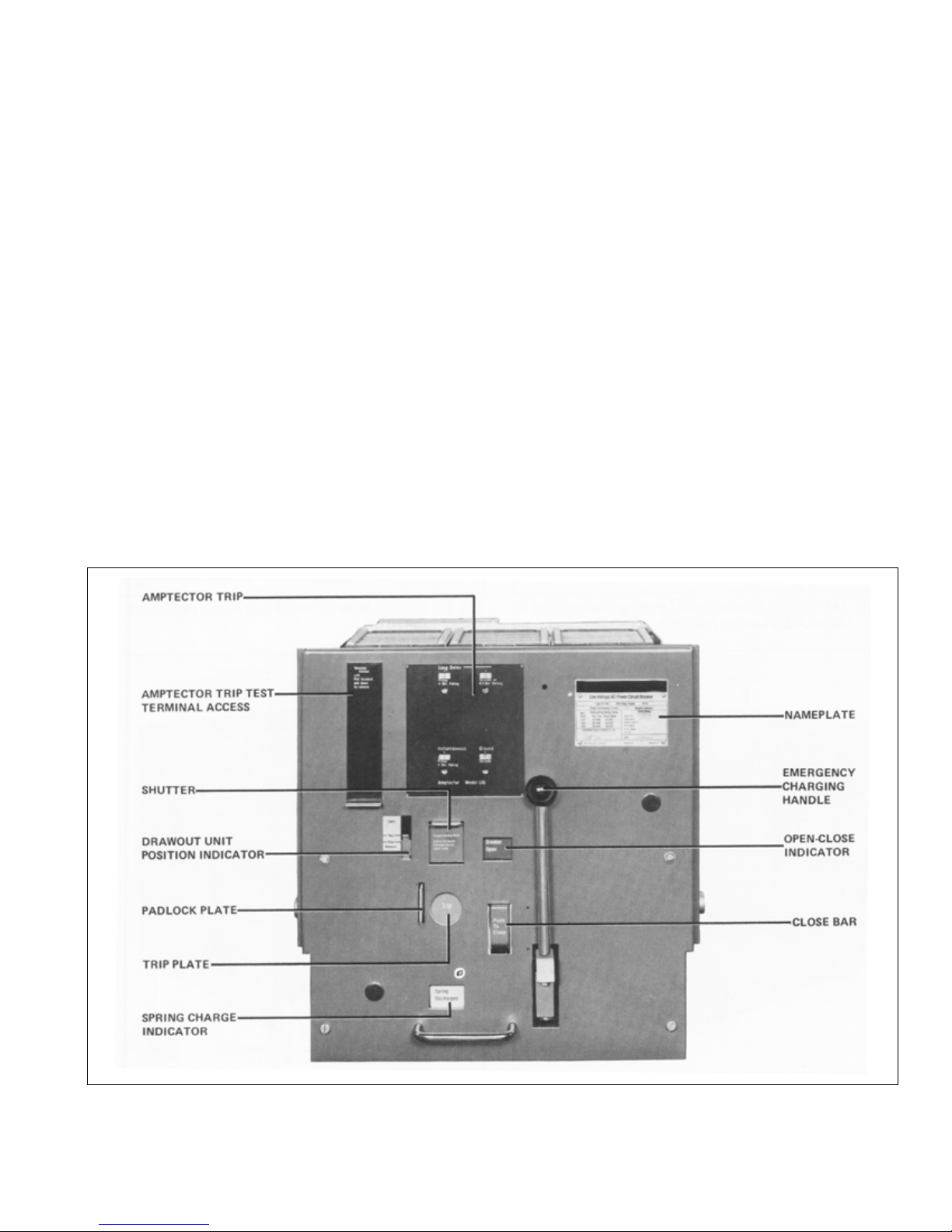
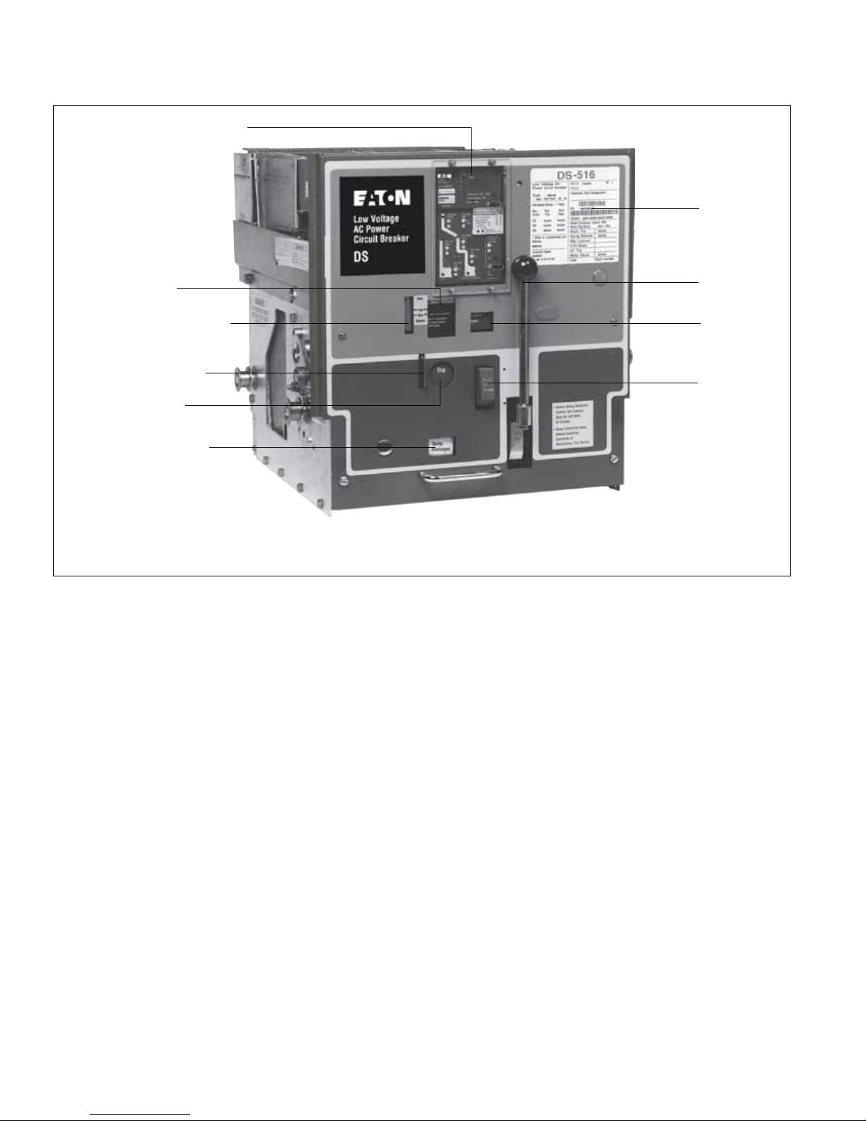
On the front of the breaker are the control items needed
for proper operation of the circuit breaker. They are:
breaker position indicator, breaker open/closed indicator
levering device shutter and shaft, breaker trip plate, closing spring charged/discharged indicator, Amptector trip
test terminal access, Amptector trip controls, closing
spring charge handle, close bar, and padlock plate.
out fuse truck, in separate interlocked compartments. Maximum interrupting rating limited to
150,000 amperes when 6000A f
uses are used.
Arc Chutes
Each arc chute contains vertical steel splitter plates, insulating spacers and plates. These are all assembled in an
GENERAL DESCRIPTION
Eaton DS and DSL Circuit Breakers are horizontal
insulating arc chute jacket. The arc chutes mount on top
of the pole units and are vented to atmosphere.
drawout magnetic air circuit breakers. They are
designed for use in Metal-Clad Switchgear assemblies
having maximum voltages of 635 volts AC for DS Circuit
Breakers and 600 volts for DSL. They are equipped with
spring-stored, energy-closing mechanisms. All primary
Optional Components
Optional components provided upon order are: under-
voltage trip attachment, overcurrent trip switch, high-load
trip switch, latch check switch, auxiliary switches.
insulation to ground is glass polyester. These breakers
have many common features, but they will vary in size
and detail
depending on the specific breaker type number
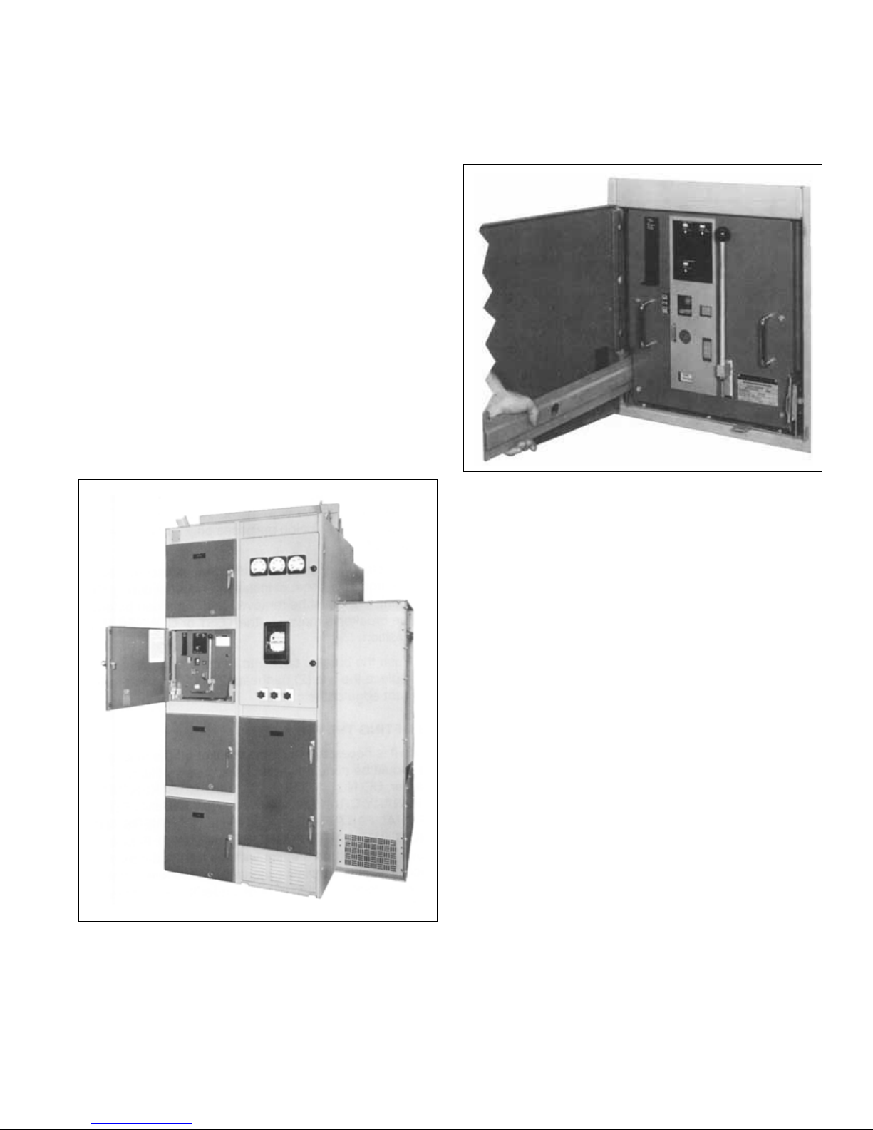
and ratings. Figure 1 shows Type DS Low Voltage Power
Circuit Breaker shipped inside its own compartment. Figures 78 and 79 show Types DSL-206 and DSL-416 Circuit Breakers.
Each DS and DSL Circuit Breaker consists of a basic
breaker assembly, three interrupter assemblies (arc
chutes), barriers, and an Amptector solid-state trip unit.
DSL breakers have added current limiters to extend their
interrupting
range to 200,000 amps. Various accessories
are also provided.
Basic Breaker Assembly
The basic breaker assembly includes a chassis, a control
panel, an operating mechanism, a levering-in device, various interlocks, and three insulated pole unit assemblies
Accessories
Levering crank and Amptector Test Kit are supplied as
required.
Since the major components and the accessories
depend on the particular type and rating of circuit
breaker, packing lists provided with each shipment and
more detailed sections of this instruction book should be
red to for special information. Any questions about
refer
the circuit breakers may be referred to the nearest Eaton
Sales Office. When making inquiries about type DS
(DSL) circuit breakers always provide the specific
type number, continuous current rating, mechanism type,
applicable order numbers, breaker shop orders or style
numbers, date of manufacture and other pertinent information as shown on the circuit breaker nameplate. Inquiries can be handled fast
er when complete information is
provided with the initial inquiry.
mounted on a base.
,
2
EATON CORPORATION www.eaton.com

Instructions for Low Voltage Power
Circuit Breakers Types DS and DSL
Instruction Booklet IB 33-790-1J
Effective November 2010
Special Circuit Breakers: DS-206S and DS-416S
Table 1 gives the interrupting rating of DS-206S as
42,000 amperes at 600 volts AC. It is an improved model
of DS-206, which has an interrupting capacity of 30,000
amperes at 600 volts AC. Yet, the maximum continuous
current rating of 800 amperes is the same for both types.
Also, their parts are similar except for these differences:
1. DS-206S uses the three piece base of the DS-416
type, instead of the one piece molded base of t
he
DS-206.
2. DS-206S uses the DS-416 arc chute.
3. DS-206S main disconnects have 50% more fingers
than the DS-206.
4. DS-206S has twice as many main contacts and arms
as the DS-206.
5. The pole unit hinge joint of DS-206S is a forked construction or a miniature version of the DS-416 hinge.
6. Fifty ampere sensors cannot be installed on
DS-206S; but they can be put on DS-206.
Similarly, the parts of DS-416S are almost identical to
those of DS-420. Their interrupting
ratings are the same:
65,000 amperes at 480 volts AC and 50,000 amperes at
600 volts AC. But, the maximum continuous current rating of DS-420 is 2,000 amperes and for DS-416S it is
1600 amperes.
Compared to Type DS-416, DS-416S has higher interrupting ratings, giving it improved operating flexibility (see
Table 1).
EATON CORPORATION www.eaton.com
3

Instruction Booklet IB 33-790-1J
Effective November 2010
Instructions for Low Voltage Power
Circuit Breakers Types DS and DSL
Safety Features
Type DS (DSL) Breakers are manufactured with several
built-in interlocks and safety features to reduce hazards
and provide proper operating sequences. UNDER NO
CIRCUMSTANCES SHOULD THEY BE MADE INOPERATIVE AS THIS MAY RESULT IN BODILY INJURY
OR PROPERTY DAMAGE.
1. Positive mechanical indicators on front panel show
whether the breaker is open or closed, and whether
the closing spring is charged or discharged.
2. Closing Spring Automatic Discharge - Mechani
interlocking automatically discharges the closing
springs when the breaker is removed from its compartment.
3. Mechanical interlocking prevents levering of breaker
unless its contacts are open. Contacts cannot be
closed until the breaker is levered into TEST or CONNECT positions.
4. Mechanical interlocking prevents closing of breaker
contacts while it is being levered into or out of its cell,
or while it is standing in any intermediate location
ween the TEST and the CONNECT positions or
bet
the DISCONNECT position.
cal
5. Provisions for Padlocking-Breakers can be padlocked
open to prevent electrical or manual closing. This
padlocking can also secure the breaker in the connected, test, or disconnected position by preventing
levering.
6. In the CONNECT position automatic mechanical
interlocking prevents the disconnecting or withdrawal
of a closed breaker. This avoids drawing dangerous,
destructive arcs on the d
the circuit is energized.
7. In the REMOVE position mechanical interlock system
prevents the closing springs from being charged or
remaining charged.
8. The integral fuses on Types DSL-206 and DSL-416
breakers are inaccessible until the breaker is completely withdrawn from its compartment, thereby
assuring complete isolation.
Likewise, the Type DSL-632 and DSL-840 fuses are inaccessible until the separate fuse truck is
drawn and the fuses isolated. The fuse truck is key
interlocked with the breaker to prevent withdrawing or
insertion unless the breaker is open.
isconnecting contacts when
completely with-
4
EATON CORPORATION www.eaton.com

Instructions for Low Voltage Power
Circuit Breakers Types DS and DSL
Recommended Safety Practices
Instruction Booklet IB 33-790-1J
Effective November 2010
Type DS circuit breakers are complex electrical devices
containing high speed, high energy, operating mechanisms. They are designed to operate within the current
and voltage limitations on the breaker nameplate. Do not
apply these breakers to systems with currents and/or
voltages exceeding these limits.
1. To perform work on Type DS Circuit Breakers
requires personnel with training and experience in
high voltage circuits. Only
ers, familiar with the construction and operation of
such equipment and the hazards involved, should be
permitted to work on these circuit breakers.
2. Only Qualified Persons as defined in the National
Electric Safety Code should be permitted to assemble, operate or maintain these breakers.
3. The breakers are equipped with various interlocks.
DO NOT MAKE ANY OF THE INTERLOCKS INOPERATIVE AS THIS MAY RESULT IN BODILY
INJURY O
4. Never put a breaker into a cell without barriers and
arc chutes.
5. Always be sure that all switch hardware is in place
and bolted tightly before inserting breaker into cell.
R PROPERTY DAMAGE.
qualified electrical work-
7. Use handle on front panel of circuit breaker to move it
into or out of cell. Keep fingers and hands off top, bot
tom or sides of breaker when moving it into or out of
cell to prevent bodily injury.
8. When operating breaker without arc chutes and barriers, keep hands, arms, head and tools out of area
where contacts travel. Severe bodily injury could
result from being struck by the moving contacts
either as they open or close.
9. Be sure circuit breaker contacts are open and closing
springs are discharged before doing maintenance
work.
10. Be sure circuit breaker
springs are discharged after completing maintenance
work.
11. Never leave breaker in an intermediate position in a
cell. Always have the breaker either in the disconnect, test or connected position because control circuits may be either improperly connected (or
disconnected) and may cause electrical failures.
12. Avoid trip-free type operation because it causes
more shock on some parts of breaker than normal
closing ope
rations. Refer to last paragraph in Item 4.1.
contacts are open and closing
-
6. Do not lift breaker with ordinary crane hooks, ropes,
chains, etc., to avoid possible damage to parts or
dropping the unit. Use breaker lifting adapter.
13. Before operating breaker in test position, be sure that
closing the breaker will not cause another electrically
interlocked breaker to inadvertently trip.
EATON CORPORATION www.eaton.com
5

Instruction Booklet IB 33-790-1J
Effective November 2010
Section 1 - Receiving, Handling and Storing
Instructions for Low Voltage Power
Circuit Breakers Types DS and DSL
1.0 RECEIVING AND HANDLING
The circuit breakers may be shipped completely assembled and inside their respective compartments.
Receiving and handling of this equipment is covered in
Eaton Instruction Book 32-690 for Low-Voltage
Metal-Enclosed Switchgear, Types DS and DSO.
If the circuit breakers are not shipped in the switchgear
assembly, they will be packed separately in individual cartons or crates. These packages must be handled with
care to avoid hidden d
If the circuit breakers have been shipped in the switchgear assembly, proceed as described in Section 2. If the
breakers have been shipped in separate packages, remove them from the crate or carton carefully so as not to
cause damage. Place the breakers on the switchgear
extension rails. (See Section 2.3 before attempting to lift
breakers.) Remove the insulating barriers and arc chutes.
Inspect the contact structures to be sure no damage has
occurred during shipment. Repla
insulating barriers and proceed as described in Section 3.
1.1 STORING
If it is necessary to store the equipment before installation, keep it in a clean dry place, protected from dirt and
water and with ample air circulation and heat, if necessary, to prevent condensation. Like all electrical apparatus, these units contain insulation. Although it is of
highest quality, it, like all other insulation, must be protected against dirt and moisture. Refer to Instruct
Book 32-690-C for details.
amage to the circuit breakers.
ce the arc chutes and
ion
Note: Breakers that have been stored or have infrequent operations shall be operated a minimum of five
times before being placed in service.
1.2 WEIGHTS: CIRCUIT BREAKERS AND FUSE
TRUCKS
Table 3 gives the approximate weights of DS and DSL circuit breakers. They will vary slightly due to the differences in functional components of the individual DS
Breaker, and the size of the current limiters supplied on
DSL Breakers. Fuse tru
ences of fuse sizes.
Table 3 - Approximate Weights
DS-206 Circuit Breaker . . . . . . . . . . . . . . 150
DS-206S Circuit Breaker . . . . . . . . . . . . . 160
DS-416 Circuit Breaker . . . . . . . . . . . . . . 195
DS-416S Circuit Breaker. . . . . . . . . . . . . 200
DS-420 Circuit Breaker . . . . . . . . . . . . . . 200
DS-632 Circuit Breaker . . . . . . . . . . . . . . 300
DS-840 Circuit B
DSL-206 Circuit Breaker . . . . . . . . . . . . . 200
DSL-416 Circuit Breaker . . . . . . . . . . . . . 260
DS-3200 Fuse Truck . . . . . . . . . . . . . . . . 325
DS-4000 Fuse Truck . . . . . . . . . . . . . . . . 430
ck weights will vary due to differ-
sdnuoPstnemelE tuowarD
reaker . . . . . . . . . . . . . . 400
6
EATON CORPORATION www.eaton.com
Instructions for Low Voltage Power
Circuit Breakers Types DS and DSL
Section 2 - First Removal of Breaker from Compartment
2.0 GENERAL
To examine and become familiar with the construction
and operation of the breaker, it first must be withdrawn
from the compartment. There are rails provided which
permit the breaker to be rolled out of the compartment so
that it can be examined on all sides and operated. First
unlatch and open the compartment door.
2.1 SETTING THE RAILS IN FRONT OF THE COMPARTMENT
Refer to Figures 1 and 2. There are two rails for each
breaker compartment whic
on the inside of the compartment in a back-sloping position. Withdraw each rail completely and let it down into a
horizontal position, as shown in Figure 2.
The first movement of the breaker toward the front of the
compartment must be done with the levering device.
h, when not in use, are stored
Instruction Booklet IB 33-790-1J
Effective November 2010
Fig. 1 The Type DS Low Voltage Power Circuit Breaker is
Shipped Inside Its Own Compartment.
Fig. 2 Rails are Stowed away in the Compartment.
Withdraw as Shown.
2.2 REMOVING SHIPPING BRACE
Before th
its compartment for the first time, two shipping braces
must be removed from the lower part of the breaker front
panel. These braces are small steel angles bolted to the
front of the circuit breaker and to the bottom cradle of the
circuit breaker compartment.
During shipment, the front wheels of the breaker are lifted
approximately 1/16 inch above the compartment rails,
and the uni
TEST positions by means of its levering device and the
shipping angle.
1. With a screwdriver, remove the two (2) outside .25-20
2. The levering device is now used to release the
e circuit breaker element can be withdrawn from
t is held part way between
panhead screws with captive washers from the bottom leg of the two angles. Do not discard, as later
they will be returned to their tapped holes. Do not
remove the center screw from the bottom cradle.
breaker from the shipping position. When the bre
is part way between DISCONNE
tions as described above the breaker levering device
interlock will hold the shutter down and the trip plate
depressed. The hex shaft of the levering device will
be exposed and ready to receive the levering crank
handle (see Figure 3). Insert the crank and turn in a
counter-clockwise direction and observe the action of
DISCONNECT and
aker
CT and TEST posi-
EATON CORPORATION www.eaton.com
7
Instruction Booklet IB 33-790-1J
Effective November 2010
the drawout position indicator. The indicator will move
down to the REMOVE position at which time the load
on the crank handle increases because a stop has
been reached.
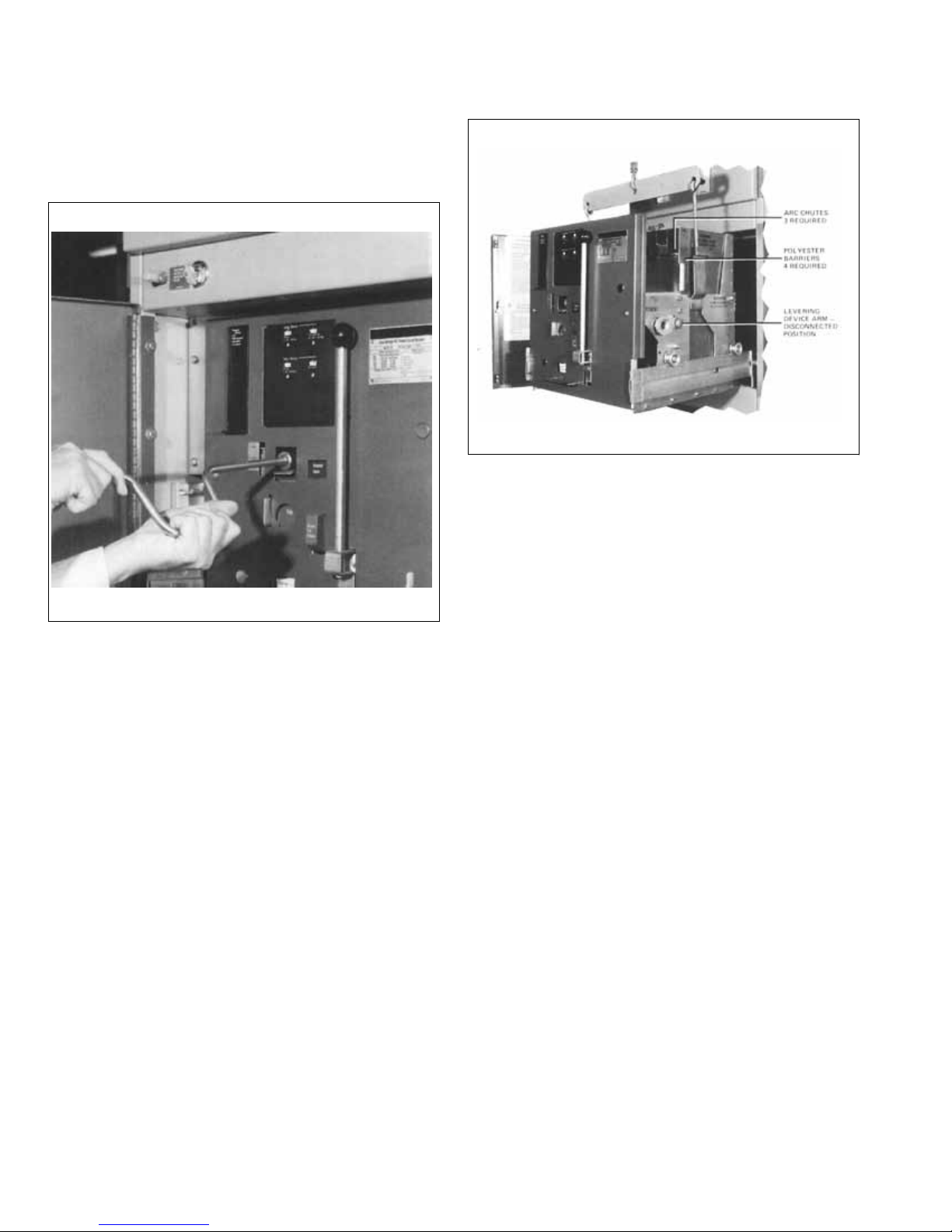
Fig. 3 Levering Device Crank Handle Installed. Read
Section 2.2 on this Operation.
Note: Do not apply force on the crank handle after
the stop has been reached as the breaker is now free.
3. When the position indicator shows the levering
device to be in the REMOVE position, remove the
hand crank. Pull the breaker out onto the extended
rails. This will require more effort than normal as the
rear wheels are jammed into the cradle hold-down
hooks by two lengths of plastic tubing. Refer to illustrations in the stationary structure Instruction Book
32-690 covering shipping braces.
4. Remove the two (2) .25-20 panhead screws holding
the two shipping angles to the front panel of the
breaker. Care must be exercised to prevent marring
front panel. Two or more flat washers are used
the
between the angle and front panel for shipping. Discard the angles.
5. Immediately replace the two panhead screws discarding all washers.
Instructions for Low Voltage Power
Circuit Breakers Types DS and DSL
Fig. 4 Use of Breaker Lifting Adapter.
6. With the breaker pulled completely to the end of the
rails, remove the two (2) six inch long pieces of split
plastic tubing that are on the rear of the stationary
rails immediately below the hold-down hooks. This
tubing is for shipping p
carded.
7. The stationary secondary disconnecting contacts are
covered by a sheet of insulating material during shipment. This must be removed and discarded before
the breaker is moved to the TEST or CONNECTED
position.
8. Push the breaker back into its compartment, and
replace the two (2) panhead .25-20 screws at the
front edge of the cradle.
2.3 LIFTING THE BREAKER
When it is necessary to lift the breaker off the rails, all lifting should be done only with the
adapter. DO NOT ATTEMPT TO LIFT BREAKER WITH
ORDINARY CRANE HOOKS, ROPES, CHAINS ETC.,
AS VITAL PARTS SUCH AS WIRING, BARRIERS AND
ARC CHUTE PARTS MIGHT BE DAMAGED. Figure 4
shows a view of the breaker with the lifting adapter in
place. The lifter consists essentially of two sheet steel
hooks specially shaped to hook under the top edges of
the large openings on each circuit breaker side sheet, or
in the specially provided lifting lugs on some break
and a spreader. Actual lifting may be with a crane, chain
block or with the optional lifting mechanism which can be
supplied for the switchgear. The breaker must be pulled
completely to the end of the rails.
urposes only and is to be dis-
accessory lifting
ers,
8
EATON CORPORATION www.eaton.com
Instructions for Low Voltage Power
Circuit Breakers Types DS and DSL
Section 3 - Preliminary Examination of Circuit Breaker
Instruction Booklet IB 33-790-1J
Effective November 2010
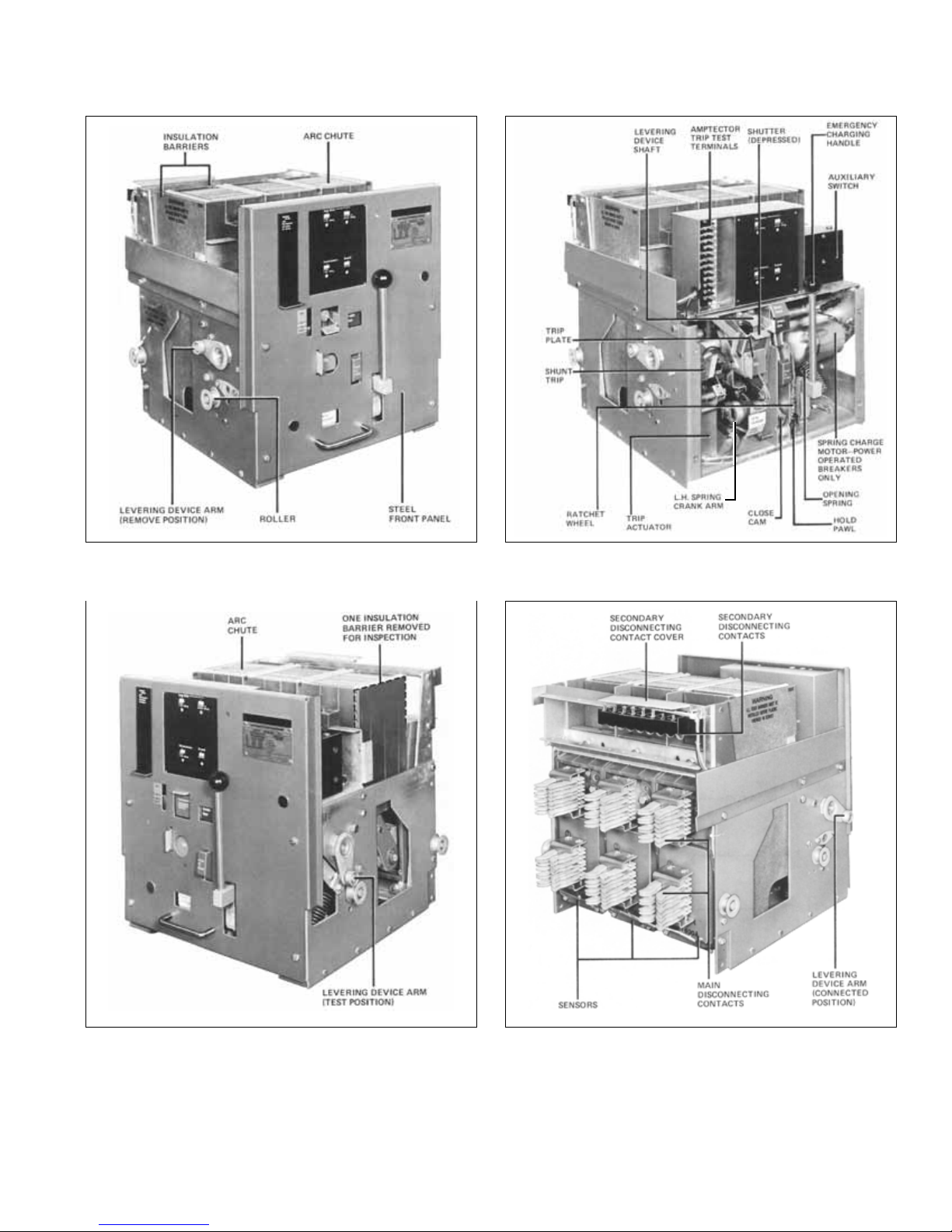
3.0 GENERAL
Read these instructions carefully and look at the breaker
as it stands out of the compartment before trying to operate it. Refer to Figures 5a, 5b, 6, 7 and 8.
The complete drawout element includes the circuit
breaker itself and its auxiliaries. The circuit breaker consists of four major components:
1. The operating mechanism.
2. The contacts, operated by the mechanism.
3. The arc chutes, which interrupt the arc which always
from opening the breaker under load or short
results
circuit conditions.
4a.
The Amptector
tem.
4b.
Digitrip
Fig. 5b).
®
®
solid-state overcurrent tripping sys-
RMS overcurrent tripping system (see
The remainder of the drawout element includes the following auxiliary components:
1. Interphase insulating barriers which isolate the arc
chutes from each other and from ground.
2. Drawout element frame and rollers.
3. The levering device, for placing the element into its
various positions inside the compartment.
4. The main disconnecting
breaker to power source and load.
5. The secondary contacts, for connecting the control
circuits to the electrical operating parts of the element.
6. The interlocks, which increase the safety of operation.
7. Drawout element position indicator.
contacts, for connecting the
Fig. 5a View Showing Controls on the Panel (Pre 1988).
EATON CORPORATION www.eaton.com
9
Instruction Booklet IB 33-790-1J
Effective November 2010
DIGITRIP RMS TRIP UNIT
SHUTTER
DRAWOUT UNIT
POSITION INDICATOR
Instructions for Low Voltage Power
Circuit Breakers Types DS and DSL
NAMEPLATE
EMERGENCY
CHARGING
HANDLE
OPEN-CLOSE
INDICATOR
PADLOCK PLATE
TRIP PLATE
SPRING CHARGE
INDICATOR
Fig. 5b View Showing Controls on the Panel (Post 1988).
CLOSE BAR
10
EATON CORPORATION www.eaton.com
Instructions for Low Voltage Power
Circuit Breakers Types DS and DSL
Instruction Booklet IB 33-790-1J
Effective November 2010
Fig. 6a Left Side of Breaker with Levering Device Arm in
REMOVE Position.
Fig. 6b DS 416 Breaker with Front Panel Removed.
Fig. 7 Right Side Showing Levering Device Arm in TEST
Position.
Fig. 8 Rear View Showing Levering Device Arm in
CONNECT Position.
EATON CORPORATION www.eaton.com
11

Instruction Booklet IB 33-790-1J
Effective November 2010
Instructions for Low Voltage Power
Circuit Breakers Types DS and DSL
8. Open-Close indicator.
9. Spring charge indicator.
10. The close bar and trip plate.
11. Steel front cover.
12. Nameplate with complete rating information.
The Type DSL-206 and DSL-416 drawout elements also
include the following components:
1. Current limiters.
2. Isolating transformers, connected in parallel with the
limiters.
3. Combination “Blown Limiter Indicator” and anti-single
phase device, connected to the isolating transformers, actuated by blowing of one or more of the current
ters. This device has individual phase indicators
limi
and a common “RESET” button extending through
the front cover.
Each breaker is equipped with a spring-type stored
energy closing mechanism. This mechanism closes the
circuit breaker contacts with the necessary speed and
force, independently of the operator. Basically, the closing springs must first be charged or cocked before the
breaker can be closed. The springs are then released by
releasing the
spring release latch. The breaker is opened
by releasing the tripping latch.
3.1 INDEPENDENT MANUAL AND POWER-
OPERATED BREAKERS
3.1.1 Closing Facilities
On manually operated breakers, the closing springs can
be charged only by hand, by means of the spring-charge
handle. The actual closing of the breaker is done only by
hand-push on the close bar. As optional equipment, the
electrical spring release attachment normally supplied
only on power-operated breakers can be supplied on
manually operated
breakers.
On power-operated breakers, the springs are normally
charged by an electric motor. Closing may be done electrically by an electro-magnet which lifts the closing spring
release latch. Both of these operations can be done by
hand if the control power source fails.
3.1.2 Tripping Facilities
The breaker can be tripped open by hand by pushing with
the finger on the trip plate on the breaker panel or the trip
plate on the breaker compartment door (the latter is oper
ative only when the breaker is in the connected position).
The breaker can also be tripped electrically by the following devices:
1. Shunt trip device, optional equipment on manually
operated breakers.
2. Trip Actuator, energized from the Amptector trip unit.
3. Undervoltage Trip Device (Optional on all breakers).
4. Blown Limiter Indicator (for DSL breakers).
3.2 LEVERING DEVICE
The drawout element has four normal positions in its
compartment, determined by the leve
ring device:
1. The REMOVE position, Figure 6.
2. The DISCONNECT position.
3. The TEST position, Figure 7.
4. The CONNECT position, Figure 8.
The REMOVE position is the first position in the compartment as the element is pushed directly by hand as far as
it will go. The DISCONNECT, TEST, and the CONNECT
positions are reached only by means of the levering
device. This is hand operated with a removable crank
handle. This handle is placed on the levering device
worm shaft, wh
ich is exposed by depressing the shutter.
-
12
EATON CORPORATION www.eaton.com
Instructions for Low Voltage Power
Circuit Breakers Types DS and DSL
Section 4 - Basic Operating Instructions
Instruction Booklet IB 33-790-1J
Effective November 2010
4.0 GENERAL
The breaker is now ready for trial mechanical operation.
Keep the breaker standing on the compartment rails, out
in front of the compartment. Examine it externally for any
signs of obvious damage or foreign material. When
everything appears to be in order, perform the following
operations as “dry run” practice. If any malfunctioning is
found during these operations, see that it is corrected
before further operations or before pl
service.
acing the breaker in
TION. Watch the movement of the levering device arms.
At the start of cranking the arms are horizontal, with rollers toward the rear, Figure 6. As the crank is turned
kwise the levering device arms rotate downward.
cloc
When they have moved approximately 40° from the horizontal, the shutter will rise until it touches the crank
socket. The position indicator will be opposite “DISC”
which is the DISCONNECT position wherein the breaker
is held in its compartment with both main and secondary
contacts disengaged. If the crank is withdrawn, the shutter will close completely, and the breaker may be locked
in this position as later described
instruction book. There is very little movement of the
breaker into its compartment between the REMOVE and
DISCONNECT positions.
Continued rotation of the crank in the clockwise direction
moves the arms downward to the vertical position, and
the indicator will show “TEST” as in Figure 7. The shutter
will rise.
Further clockwise rotation of the crank handle rotates the
arms to the CONNECT position. This is about 65
degrees from the test
When this position is reached, the crank suddenly
becomes hard to turn. At this point, stop turning the
crank, as the worm shaft bottoms in the tapped hole of
the stop nut.
position, as shown in Figure 8.
in Section 5.1.8.5 of this
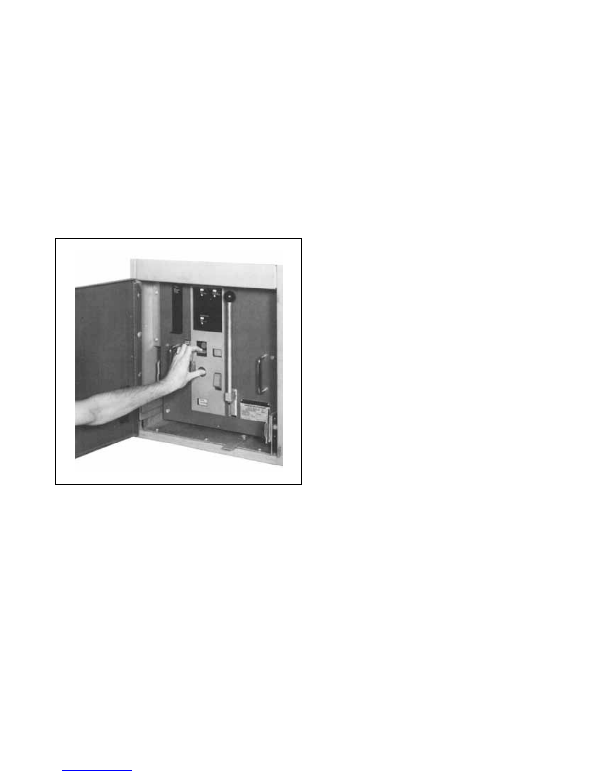
Fig. 9 Method Used to Press Trip Plate and Lower
Shutter with One Hand, Preparatory to
Inserting Crank.
4.1 LEVERING DEVICE
If the circuit breaker was shipped in a separate package,
the levering device was probably left in the REMOVE
position. If not it will be necessary to return it to this position. Push in the TRIP plate and depress the shutter over
the levering shaft, using one hand, as shown in Figure 9,
and insert the levering crank as sh
the crank counterclockwise until the position indicator is
in the REMOVE position, at which time the load on the
crank handle increases because a stop has been
reached. Now rotate the crank clockwise to simulate
levering the breaker inward toward the CONNECT POSI-
own in Figure 3. Turn
Note: Further turning effort is useless. The breaker
will be secure, even if the stop is only lightly
touched. Remember this when actually levering the
breaker into the connect position.
Rotation of the crank counterclockwise will turn the levering device arms to withdraw the unit from the
position to the TEST position and then to the DISCONNECT and REMOVE positions. Then, when the crank is
removed from the worm shaft, the shutter will remain
down and the trip plate will remain trapped by the shutter.
Note: If the breaker is levered out from the TEST
position to the REMOVE position with the closing
springs charged, a trip-free “closing” operation automatically will be performed but the breaker contacts
will not close. When a power-operated breaker is
emoved from cell, it must go through a trip-free
r
operation.
4.2 CHARGE THE CLOSING SPRINGS
The closing springs must be charged before the breaker
can be closed. To manually charge the closing springs,
CONNECT
EATON CORPORATION www.eaton.com
13
Instruction Booklet IB 33-790-1J
Effective November 2010
Instructions for Low Voltage Power
Circuit Breakers Types DS and DSL
the levering device arms must be rotated away from the
REMOVE position to the TEST position. If charging is
attempted in the REMOVE position, the closing cam will
rotate past the charged position and go through a
trip-free “closing” operation, i.e., the springs will discharge without moving the breaker contacts. Do not
attempt to charge the springs in the DISCONNECT position as the same action may occur. After turning the
levering device to TEST position, manually charge th
springs. On manually operated breakers, the springs are
charged by a single stroke downward on the
spring-charge handle, rotating it about 90° toward you
until it suddenly becomes very easy to move and then
tends to run away from your hand. At the same time, you
will hear a metallic “click!” as the over center closing
spring stop is reached. Note that the spring charge indicator now shows “Spring Charged.”
e
CAUTION
DO NOT RELEASE THE HANDLE BEFORE THE
HARGING OPERATION IS COMPLETED. TO
C
RELEASE HANDLE BEFORE CHARGING COMPLETION WILL RETURN HANDLE UPWARDS WITH SUCH
VELOCITY THAT IT MAY BREAK THE HANDLE KNOB
OR CAUSE BODILY INJURY.
CAUTION
HOLD BREAKER TO PREVENT TILTING FORWARD
WHEN HAND CHARGING CLOSING SPRINGS WITH
THE BREAKER ON THE EXTENDED RAILS. OTHERWISE, IT MAY TOPPLE TO THE FLOOR AND CAUSE
BODILY INJURY OR EQUIPMENT DAMAGE.
On power operated breakers, a short spring-charge handle is included for emergency operation. This works on a
ratchet
tions to completely charge the springs. At this point, the
same metallic “click” will be heard; and the spring charge
indicator will show “Spring Charged.” The handle must
not be forced beyond this point.
Note: Power-operated breakers, when being levered
into the compartment, will have the spring-charge
motor run and charge the spring automatically as the
TEST position is reached.
4.3 CLOSE THE BREAKER
The breaker can be closed only w
tions are met:
principle, and requires 10 to 12 pumping opera-
hen the following condi-
1. The closing springs are charged.
2. The levering arms are in either the TEST position, as
in Figure 7 or in the CONNECT position, Figure 8.
3. The levering device crank handle has been removed
and the shutter is closed.
4. Undervoltage trip device (if included) has been energized.
5. Blown limiter indicator (for DSL breakers only) is
reset.
Having met these conditions, close the breaker by pushing on the close ba
cator shows “Breaker Closed”, against a red background.
Also that the spring-charge indicator now shows “Spring
Discharged.”
Some power-operated breakers are interlocked to prevent manual closing from the close bar on the front panel
when in the CONNECT position. In this case crank the
levering device to the TEST position to operate. This
interlock is covered by Section 5.1.8.2.
It is possible to recharge the springs immed
closing the breaker. This results in increased strain on
the mechanism, and it is recommended that this be done
only if the operating procedure requires this condition.
Note: If closing is attempted with the levering arms in
other than the TEST or CONNECT positions, with or
without the levering crank in place, a trip-free “closing” operation is performed but the breaker contacts
do not close. This trip free type of operation results
in more shock on some
normal closing operations. Therefore, this type of
operation should be avoided if possible.
4.4 OPEN THE BREAKER
The breaker can be opened in the following ways:
1. By hand operation of the trip plate (on the breaker or
on the compartment door.)
2. Automatically by overload, short circuit or undervoltage condition.
3. Breakers equipped for power operation can be
tripped electrically by a shunt trip device energized
by hand switch
For the present purpose of getting acquainted with the
breaker, open it by pushing on the trip plate. Note that the
breaker position indicator now shows “Breaker-open”,
against a green background.
r. Note that the breaker position indi-
iately after
parts of the mechanism than
or relay.
14
EATON CORPORATION www.eaton.com

Instructions for Low Voltage Power
Circuit Breakers Types DS and DSL
Instruction Booklet IB 33-790-1J
Effective November 2010
Note: On breakers equipped for power operation,
when they are in the compartment and in either the
TEST or CONNECT position, the spring-charge motor
normally runs automatically and charges the closing
springs as soon as the breaker opens. The closing
springs normally remain discharged while the
breaker stands in the closed position. Also see Section 5.1.2.1.
Now to become better acquainted with the breaker,
charge the closing springs, close and open the breaker
several times. Also, place
the levering crank handle on
the levering device work shaft and rotate the levering
arms to their various positions by turning the levering
crank handle. Leave the levering arms horizontal, with
rollers toward rear of breaker, i.e. in the remove position.
The breaker is now ready to be put into its various operating positions in the compartment.
4.5 PLACE THE BREAKER IN THE TEST POSITION
Push the breaker into the REMOVE position.
YOU WILL NOTE THAT, WITH THE COMPA
RTMENT
DOOR OPEN, THE FRONT PANEL ASSEMBLY OF
THE BREAKER FORMS A STEEL PROTECTIVE
SHIELD.
Place crank on the levering device worm shaft. Turn
crank clockwise until drawout unit position indicator
shows “TEST.” Remove the levering device crank. The
shutter will close over the hex shaft. All manual operations can now be performed. On power operated breakers the spring is charged automatically as the breaker
arrives in the TEST position. The break
er can also be
opened with the shunt trip device, and it can be electrically closed with the spring release device.
4.6 PLACE THE BREAKER IN THE CONNECT
POSITION
Press the trip plate and lower the shutter. Place the crank
handle on the levering device worm shaft and turn the
crank clockwise until the CONNECT position stop is
reached, as indicated by sudden increase in load on the
crank, as previously described in paragraph 4.1.
Note however, that before the stop is
reached, an
increase in load on the crank will be felt after the breaker
has moved about an inch. This is caused by the making
up on the main disconnecting contacts. The load on the
crank will decrease after reaching a peak. The next
increase in load is when the stop is reached.
Note: Do not try to crank after the stop is reached.
Further tightening of the crank does not help keep
the breaker in position. When the crank handle is
removed, the shutter and
the trip plate should snap
into normal position.
4.7 REMOVE THE BREAKER FOR FINAL
INSPECTION
Withdraw the breaker from the CONNECT position in the
compartment to the end of the extended rails following
the reverse procedure described above. Inspect it thoroughly to see that no foreign objects have lodged within
it. If any defects were found during these preliminary
operations, complete their corrections at once.
4.8 FINAL INSPECTION
MAKE SURE THE THREE (3) ARC CHUTES ARE
OPERLY INSTALLED. MAKE SURE ALL FOUR (4)
PR
INSULATING BARRIERS ARE PROPERLY INSTALLED.
1. With the breaker withdrawn, rotate levering device to
connected position before attempting to charge the
spring.
2. Close and trip the breaker several times as previ-
ously described.
3. Return the levering device to the remove position;
i.e., with the roller arms pointing toward the rear as
shown in Figure 6.
4. This completes the “dry run.”
4.9 AMPTECTOR TRIP SETTINGS
When the break
er is shipped, the calibrating dials of the
Amptector trip unit are at the nominal settings. For specific overload tripping characteristics to coordinate with
the load or the system, refer to Section 8 and Curves
found later in this instruction book.
4.10 PLACE THE BREAKER IN SERVICE
Lever the breaker into the connected position as previously described, and latch the compartment door.
EATON CORPORATION www.eaton.com
15
Instruction Booklet IB 33-790-1J
Effective November 2010
Section 5 - Description and Explanation of Operation
5.0 GENERAL
The following paragraphs give a general description and
explanation of the operation of the breaker.
5.1 THE OPERATING MECHANISM AND HOW IT
WORKS
The operating mechanism is of the spring charged stored
energy type. This means that it consists of two major
parts:
(1) The stored energy or spring-charging mechanism.
(2) The mechanism for closing and opening the breaker.
The basic parts of these are combined into one
sub-assembly illus
There are two varieties of mechanisms for the complete
line of DS and DSL breakers:
trated in Figures 10, 11, 12, and 13.
Instructions for Low Voltage Power
Circuit Breakers Types DS and DSL
Power-Operated; and
Manually Operated.
Fig. 11 Front View of Mechanism (Power-Operated
Spring Charge).
Fig. 10 Front View of Mechanism (Manual Spring Charge
Except for DS-632/840).
16
EATON CORPORATION www.eaton.com
Fig. 12 Rear of Power-Operated Mechanism.
Instructions for Low Voltage Power
Circuit Breakers Types DS and DSL
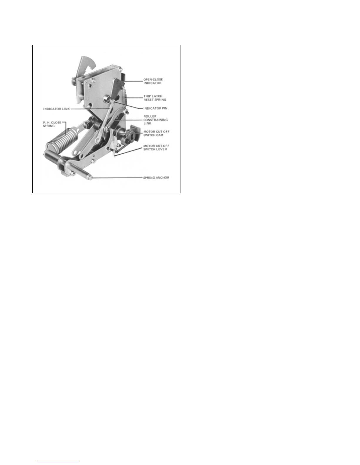
Fig. 13 Rear View of Mechanism (Left Close Spring
Removed).
Instruction Booklet IB 33-790-1J
Effective November 2010
Referring to Figure 15, the basic elements are mounted
on the crank shaft (8). This is a straight shaft with four
flats machined on it, and a crank arm (11) attached
each end. Each crank arm connects to its closing spr
(9) by a formed spring end (10) Figure 16b. The rear of
the springs anchor to the rear of the mechanism frame.
The crank arms (11), motor cutoff switch cam (7), close
cam (6) and two drive plates (25) have matching flats;
and are thus anchored to the crank shaft. The spring
charge indicator (12) ratchet wheel (17), oscillator (30),
and emergency charge device (26) do not have internal
flats but ar
to rotate on the
e mounted on separate bushings and are free
crank shaft.
Figure 17 is an exploded view of the crankshaft parts.
Figure 16a is a view looking into the right end of the
crankshaft, and shows the position of the components
when the springs are charged.
Figure 16b is a partial view with the springs discharged.
The motor crank shaft assembly (29), carrying a roller for
driving the oscillator, is pivoted in the right hand mechanism side frame. The hold
means of a pin on the mechanism
pawl (18) is mounted by
side frame as shown.
to
ing
5.1.1 Power-Operated Mechanism
In the power-operated version, the mechanism is
equipped with a universal-type motor for automatic
charging of the closing springs. It is equipped with a
spring release device for electrically closing through a
control switch pushbutton, or other circuit-making device.
A shunt trip device is supplied for remote tripping through
a control switch, relay, etc. In the absence of control
age, or whenever desirable, the closing spring ca
volt-
n be
charged by hand with the emergency charging handle.
Hand closing of the breaker can be done by means of the
close bar. Hand opening of the breaker can be done by
means of the trip plate.
5.1.2 Explanation of Spring-Charging Mechanism for
Power-Operated Breakers
Figure 14 is an isometric diagram of the principal parts of
a completely power-operated mechanism.
Figure 15 is a front view drawing sho
parts of the spring-charging port
wing the principal
ion of this mechanism.
Other parts are omitted for clarity. Figures 16a and 16b
show in greater detail the major parts of the spring-charging mechanism in the two basic positions:
Closing springs charged (16a); and
Closing springs discharged (16b).
In operation, rotation of the motor crank pushes the oscillator arm counterclockwise to make the oscillator pawl
(28) push a tooth in the ratchet wheel (17) and rotate the
ratchet wheel slightly more than one tooth in the counterclockwise direction. The holding pawl snaps behind the
corresponding advanced tooth, and holds it against the
torque of the closing springs while the oscillator
arm
rotates back clockwise to catch another ratchet tooth.
Thus the ratchet wheel is rotated counterclockwise until
the ratchet wheel pin (21) engages the two drive plates
(25) which in turn rotate the crank shaft and the crank
arms in the same direction until the arms are slightly past
horizontal dead center. Since the close cam (6) is rigidly
mounted on the crank shaft, the same as the drive plates,
it has rotated the same amount as the plates. The close
cam carrie
after
s a stop roller as shown in Figure 22b. Just
horizontal dead center of the crank arms is reached,
the torque of the closing springs starts to rotate the
crank, independently of the driving motor. However, the
stop roller on the close cam quickly stops the movement
of the crank at only a few degrees over center and holds
it there by coming against the spring release latch. This is
the “spring charged” position. The motor cut-off switch
cam
(7) operates the switch (15) through a lever (13) at
is time, and the motor stops.
th
At the instant that the springs snap over dead center, the
lobes of the drive plates raise the pawl lifters (27), and
EATON CORPORATION www.eaton.com
17
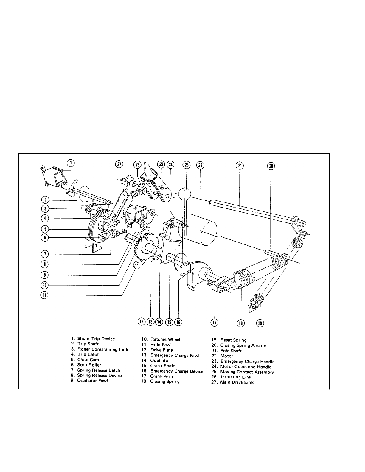
Instruction Booklet IB 33-790-1J
Effective November 2010
Instructions for Low Voltage Power
Circuit Breakers Types DS and DSL
prevent the oscillator pawl (28) from engaging the next
tooth in the ratchet wheel. Thus the oscillator is free and
renders the exact stopping point of the motor not critical.
When the spring release latch is moved below the level of
the stop roller, as later described, the close cam is free to
rotate; and the two closing springs rotate the crankshaft
counterclockwise to close the breaker contacts. They
assume the position shown in Figure 16b and the cam as
22c. During rotation, the drive plates move away from
in
the ratchet wheel pin. The ratchet wheel does not rotate
during the closing operation thus preventing excessive
wear on the teeth and pawls.
Power-operated breakers are also equipped for emergency hand charging the closing springs. Refer to Figure
21. This operation is similar to that of the motor and oscillator except a separate emergency charge pawl (33) is
used to advance the ratchet wheel (17) seve
ral teeth on
each stroke of the charge handle (34). This device (26)
also pivots on the crank shaft.
5.1.2.1 Power Operation
The electrical operation of the spring-charging motor circuit is as follows:
The standard basic schematic and connection diagrams
are shown in Figure 19a and b. Device Y is the anti-pump
relay.
Fig. 14 Arrangement of the Principal Parts of a Power Operated Mechanism. The Close Spring is Shown in the
Charged Position.
18
EATON CORPORATION www.eaton.com
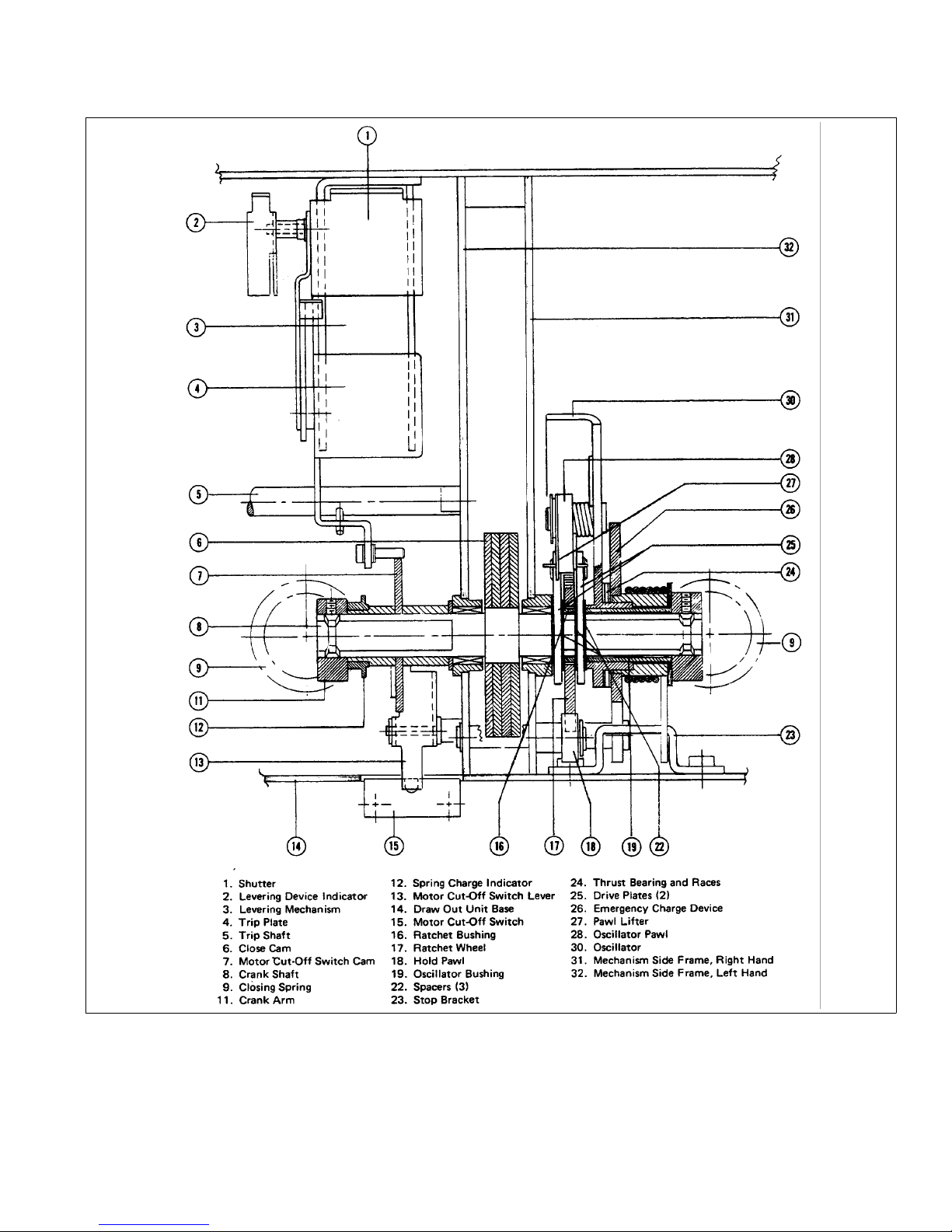
Instructions for Low Voltage Power
Circuit Breakers Types DS and DSL
Instruction Booklet IB 33-790-1J
Effective November 2010
Fig. 15 Front View Showing Major Parts of the Crank Shaft Assembly. Some Parts Are Omitted for Clarity.
EATON CORPORATION www.eaton.com
19
 Loading...