

Eaton DNP MINT, Cuttler-Hammer DNP MINT Installation And Use Manual
Instruction Leaflet IL66A7638H03
Effective December 2010
Supersedes IL66A7638H03 09/07
Instructions for DNP MINT Translator Module
Installation and Use

Instruction Leaflet IL66A7638H03
Effective December 2010
Instructions for DNP MINT Translator Module
Installation and Use
ii
EATON CORPORATION www.eaton.com
Instructions for DNP MINT Translator Module
I.L. 66A7638H03
Instructions For
DNP MINT Translator Module
Installation and Use
Installation and Use
Instruction Leaflet IL66A7638H03
Effective December 2010
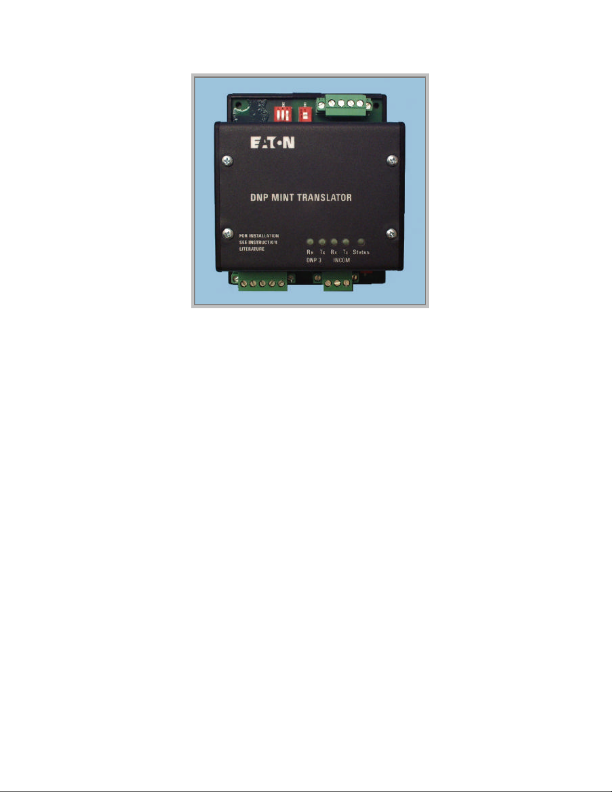
Figure 1: The DNP MINT Module
Table Of Contents
1.0 GENERAL DESCRIPTION .....................................................................................................3
2.0 FEATURES.............................................................................................................................3
3.0 INSTALLATION.....................................................................................................................3
3.1 INCOM Network ..................................................................................................................4
3.2 DNP RS-485 Network...........................................................................................................4
4.0 DNP MINT CONNECTIONS...................................................................................................4
4.1 Power Connections ................................................................................................................5
4.2 INCOM Connections .............................................................................................................5
4.3 RS-485 Connections ..............................................................................................................5
5.0 SWITCHES AND INDICATOR LEDS.....................................................................................5
5.1 DNP RS-485 Network Rx LED [Green] .................................................................................6
5.2 DNP RS-485 Network Tx LED [Green]..................................................................................6
5.3 INCOM Network Rx LED [Green].........................................................................................6
5.4 INCOM Network Tx LED [Green].........................................................................................6
5.5 Status LED [Green] ...............................................................................................................6
EATON CORPORATION www.eaton.com
1

Instruction Leaflet IL66A7638H03
I.L. 66A7638H03
Effective December 2010
5.6 INCOM 100 Ω Termination DIP Switch (SW1) ......................................................................6
5.7 DNP RS-485 Baud Rate DIP Switch (SW2) ............................................................................6
5.8 DNP Diagnostics Enable (Configuration Mode) Switch (SW2).................................................6
5.9 DNP/RS-485 121 Ω Termination DIP Switch (SW3) ...............................................................6
6.0 DNP V3.00 DEVICE PROFILE................................................................................................6
7.0 DNP MINT CONFIGURATION USING AUTO LEARN ..........................................................7
8.0 DNP MINT CONFIGURATION USING DNP COMMUNICATIONS .......................................8
8.1 Configuration With Pre-Defined Tables..................................................................................8
8.2 Configuration Of Summary Table Settings............................................................................ 10
8.2.1 DNP Master Station Address.........................................................................................10
8.2.2 DNP Address...............................................................................................................11
8.2.3 Configuration Tag.........................................................................................................11
8.2.4 DNP Transfer Protocol..................................................................................................12
8.2.5 DNP Network Idle Time To Initiate Unsolicited Transmission.........................................12
8.2.6 DNP Network Unsolicited Retry Random Time Increment Mask.....................................12
8.2.7 DNP Data Link Confirmation Wait Timeout...................................................................12
8.2.8 DNP Application Confirmation Wait Timeout................................................................ 13
8.2.9 INCOM Scan Level Settings..........................................................................................13
8.2.10 DNP Object Variation Default Settings ..........................................................................13
8.2.11 INCOM Address Settings ..............................................................................................13
8.2.12 INCOM Scan List Index Settings................................................................................... 14
8.3 Configuration With File Transfers........................................................................................15
Instructions for DNP MINT Translator Module
Installation and Use
List of Figures
Figure 1: The DNP MINT Module ......................................................................................................1
Figure 2: DNP MINT in a Communications Network...........................................................................4
Figure 3: Connections ........................................................................................................................5
Figure 4: Switches .............................................................................................................................5
List of Tables
Table 1: Power Connector Pin Outs ....................................................................................................5
Table 2: INCOM Connector Pin Outs..................................................................................................5
Table 3: DNP RS485 Connector Pin Outs............................................................................................5
Table 4: RS-485 Baud Rate Switches..................................................................................................6
Table 5: RS-485 Diagnostics Enable (Configuration Mode) Switch.......................................................6
Table 6: Auto Learn INCOM Devices.................................................................................................7
Table 7: Pre-Configured Counter Assignments ....................................................................................9
Table 8: DNP MINT Summary Table Definitions ..............................................................................11
Table 9: Device Summary Table Definitions......................................................................................14
Table 10: Device Assignments for Pre-Defined Configuration Tags ....................................................19
Table 11: Primary Status Code Definitions ........................................................................................69
Table 12: Secondary Status Code Definitions..................................................................................... 69
Table 13: Cause-of-Status Code Definitions ......................................................................................70
Table 14: MPCV Relay Primary / Secondary / Cause Decoding..........................................................73
Table 15: MPCV Relay Product ID Decoding....................................................................................74
2
EATON CORPORATION www.eaton.com

Instructions for DNP MINT Translator Module
I.L. 66A7638H03
Installation and Use
Instruction Leaflet IL66A7638H03
Effective December 2010
1.0 GENERAL DESCRIPTION
The DNP MINT (DNP Master INCOM Network
Translator) Module, as seen in Figure 1, is a
Eaton Electrical accessory product that will
provide communication between a DNP 3.0
network master and an INCOM (INdustrial
COMmunications) network of MPCV Relays
(see Figure 2). The module is transparent to the
DNP network master. It communicates to a
master on the DNP network using the DNP 3.0
protocol. It communicates to slave devices on
the INCOM network using the IMPACC
(Integrated Monitoring, Protection, And Control
Communication) protocol.
2.0 FEATURES
The DNP MINT module is a slave device on the
DNP network and as such requires a master that
will poll/accept DNP objects from the DNP
MINT module.
• DNP communications data transfer rates of
1200, 9600, or 19200 baud with 1 start bit, 8
data bits, no parity and either one or two
stop bits.
3.0 INSTALLATION
The DNP MINT module is designed to be
installed, operated and maintained by adequately
trained personnel. These instructions do not
cover all of the details or variations of the
equipment for its storage, delivery, installation,
checkout, safe operation or maintenance. When
mounting the DNP MINT verify that a “C”
Shape 32mm or Standard 35/7.5mm DIN Rail
is used and that it is within an enclosed space.
WARNING
DO NOT ATTEMPT TO INSTALL OR
PERFORM MAINTENANCE ON
EQUIPMENT WHILE IT IS ENERGIZED.
DEATH OR SEVERE PERSONAL INJURY
CAN RESULT FROM CONTACT WITH
ENERGIZED EQUIPMENT. ALWAYS
VERIFY THAT NO VOLTAGE IS
PRESENT BEFORE PROCEEDING.
ALWAYS FOLLOW SAFETY
PROCEDURES. EATON ELECTRICAL
INC. IS NOT LIABLE FOR THE
MISAPPLICATION OR
MISINSTALLATION OF ITS PRODUCTS.
• Up to 16 devices such as the MPCV Relay
connected to the INCOM network port.
• Flashing Status LED to indicate an active
module.
• LED indicators for DNP RS-485 transmit
and receive communications exchanges.
• LED indicators for INCOM transmit and
receive communications exchanges.
• Input power for the module from either 120
VAC or 24 to 125 VDC.
• DIN rail mount package.
• -40ºC to 85ºC ambient operation.
EATON CORPORATION www.eaton.com
3
Instruction Leaflet IL66A7638H03
I.L. 66A7638H03
Effective December 2010
DNP3.0
DNP3.0
RS -485
RS -485
DNP
DNP
MIN T
MIN T
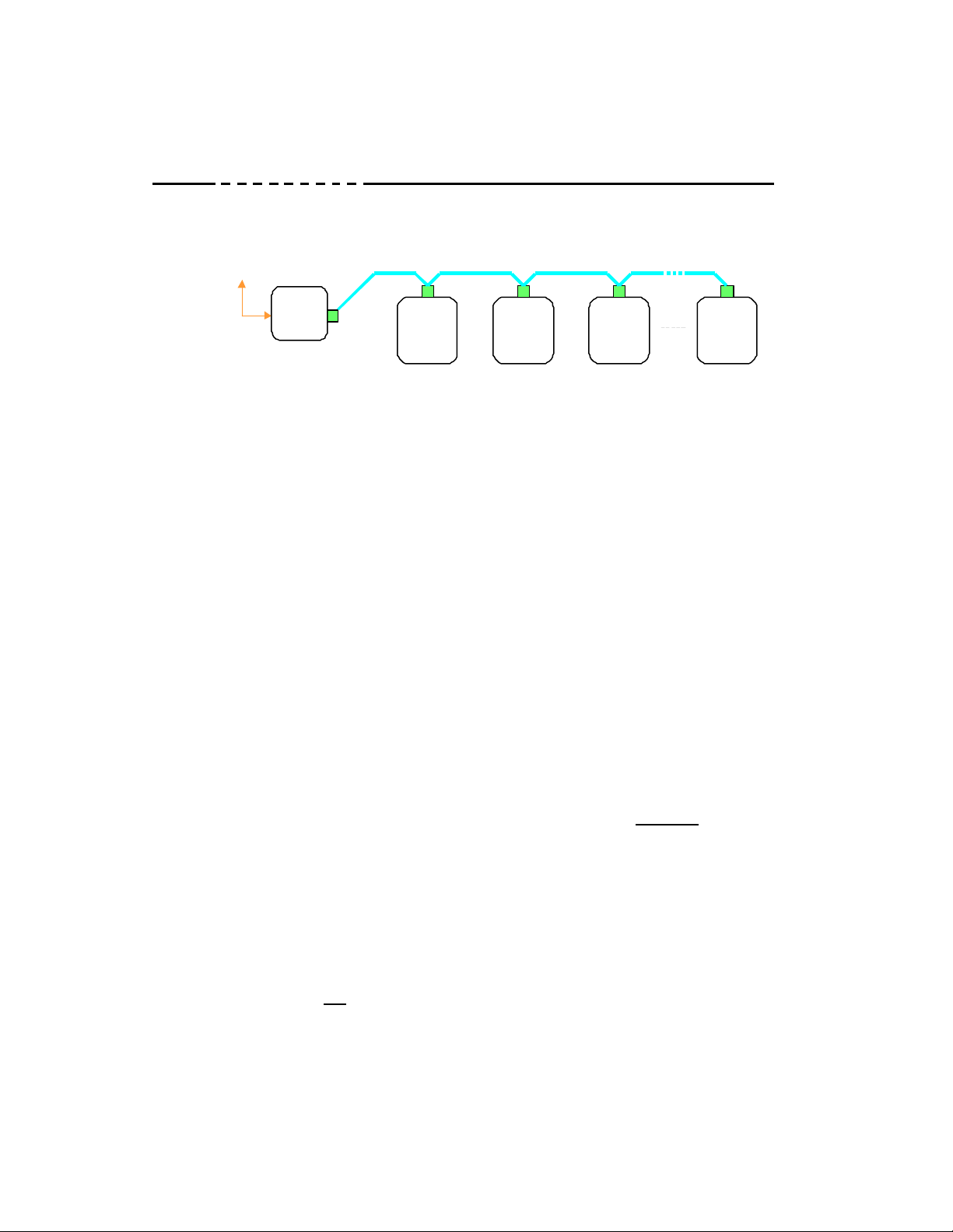
Figure 2: DNP MINT in a Communications Network
MPCV
MPCV
STREET LEVELVENT/GRATING
STREET LEVELVENT/GRATING
INCOM Network
INCOM Network
MPCV
MPCV
Instructions for DNP MINT Translator Module
Installation and Use
UNDERGROUND
UNDERGROUND
MPCV MPCV
MPCV MPCV
3.1 INCOM Network
The following simplified rules apply to a given
system consisting of a single daisy chained main
cable link between master and slave devices (see
Figure 2). For more complex considerations
including star configurations, please refer to the
IMPACC wiring specification T.D. 17513.
• Recommended INCOM cable styles are
Belden 3073F or C-H style 2A957805G01.
• The maximum system capacity is 8,000 feet
of communications cable and 16 slave
devices such as the MPCV Relay on the
INCOM network under the DNP MINT.
• Non-terminated taps, up to 200 feet in
length, off the main link are permitted, but
add to the total cable length.
Make sure that there is twisted-pair wire that is
recommended for IMPACC network use. Use
shielded twisted-pair wire to connect each slave
to the INCOM network, daisy-chain style. The
polarity of the twisted pair is not important.
3.2 DNP RS-485 Network
The following simplified rules apply to a given
system consisting of a cable link between master
and slave devices (see Figure 2).
• The recommended DNP cable has
twisted-pair wires (24 AWG stranded 7x32
conductors with PVC insulation) having an
aluminum/mylar foil shield with drain wire.
• Make sure that there is twisted-pair wire that
is recommended for serial DNP RS-485
network use. Use shielded twisted-pair wire
to connect each slave to the DNP network,
daisy-chain style. The polarity of the
twisted pair is critically important.
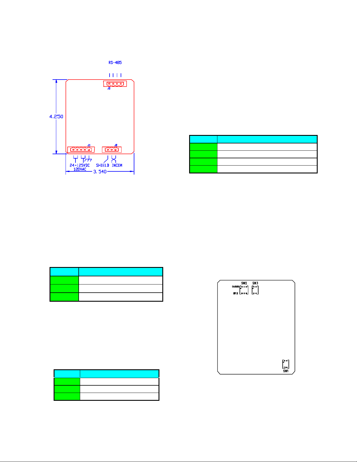
4.0 DNP MINT CONNECTIONS
Refer to Figure 3 and the following three pin
out tables for installation specifics.
4
EATON CORPORATION www.eaton.com
Instructions for DNP MINT Translator Module
I.L. 66A7638H03
Installation and Use
Instruction Leaflet IL66A7638H03
Effective December 2010
DNP
DNP
B A COM SHD
B A COM SHD
Figure 3: Connections
4.1 Power Connections
Connect the shield wire to ground at master
device end only. Interconnect shielding where
devices are daisy chained.
4.3 RS-485 Connections
DNP RS-485 Connector: This 4-pin connector
provides the interface to the DNP network. The
polarity is “critically” important. Refer to Table
3.
Pin # Input / Output Signal
1 RS485 Network-B (non-inverting)
2 RS485 Network-A (inverting)
3 Common
4 Shield
Table 3: DNP RS485 Connector Pin Outs
RS-485 Network-A is the inverting differential
connection for the DNP network. RS-485
Network-B is the non-inverting differential
connection for the DNP network.
Power Connector: Module power uses a 5-pin
input connector (see Figure 3). Power
requirements are 120 VAC, 60 Hz or
24-125VDC. Refer to Table 1.
Pin # Input Power
1 Chassis Ground
2 & 3 VAC Neut. / VDC Common
4 & 5 VAC Line / 24-125 VDC+
Table 1: Power Connector Pin Outs
4.2 INCOM Connections
INCOM Connector: This 3-pin connector
provides the interface to the INCOM network.
Refer to Table 2.
Pin # Input / Output Signal
1 INCOM Carrier Network
2 INCOM Carrier Network
3 Shield
5.0 SWITCHES AND INDICATOR
LEDS
Figure 4: Switches
Table 2: INCOM Connector Pin Outs
Refer to Figure 1 to locate the Status LED for
the DNP MINT. Figure 4 shows the location of
the configuration switches.
EATON CORPORATION www.eaton.com
5
Instruction Leaflet IL66A7638H03
I.L. 66A7638H03
Effective December 2010
Instructions for DNP MINT Translator Module
Installation and Use
5.1 DNP RS-485 Network Rx LED
[Green]
The LED will be illuminated whenever the DNP
MINT is receiving content from activity on the
DNP network.
5.2 DNP RS-485 Network Tx LED
[Green]
The LED will be illuminated whenever the DNP
MINT is transmitting on the DNP network.
5.3 INCOM Network Rx LED [Green]
The LED will be illuminated whenever the DNP
MINT is receiving messages from the INCOM
network.
5.4 INCOM Network Tx LED [Green]
The LED will be illuminated whenever the DNP
MINT is transmitting messages on the INCOM
network.
5.5 Status LED [Green]
This indicator will begin flashing after the
module has powered up, its processor has
performed its RAM tests and the microcontroller
is executing instructions. The flashing rate is
approximately 1 second ON / 1 second OFF.
This indicator will flash at a rate of
approximately 5 times a second during an auto
learn dip switch detection sequence (see Section
7.0).
After accepting a configuration request, the DNP
MINT will hold this LED ON for approximately
2.5 seconds.
5.7 DNP RS-485 Baud Rate DIP
Switch (SW2)
To set the data transfer rate for the DNP
network, two switches in dip switch SW2
(SW2-2 and SW2-3) should be moved to either
the “CLOSE” or the “OPEN” position based on
the rate required. Refer to Table 4. SW2-1 is
for DNP MINT configuration.
Baud SW2-1 SW2-2 SW2-3
1200 X CLOSE CLOSE
9600 X OPEN CLOSE
19200 X CLOSE OPEN
Table 4: RS-485 Baud Rate Switches
5.8 DNP Diagnostics Enable
(Configuration Mode) Switch
(SW2)
To configure the DNP access settings and the
INCOM device access settings within the DNP
MINT, the SW2-1 dip switch must be moved to
the “OPEN” position. Refer to Table 5.
Normally, this switch is in the “CLOSE”
position. Changing this dip switch
automatically forces a reset of the DNP MINT.
Baud SW2-1 SW2-2 SW2-3
Configure OPEN X X
Normal CLOSE X X
Table 5: RS-485 Diagnostics Enable
(Configuration Mode) Switch
5.9 DNP/RS-485 121 ΩΩ Termination
DIP Switch (SW3)
This switch should be set to the “ON” position
only when it is the last unit in a chain or if it is
the only outstation device on the DNP Network.
5.6 INCOM 100 ΩΩ Termination DIP
Switch (SW1)
This switch should be moved to the “ON”
position only when it is the last unit in a chain of
units or if it is a single unit.
6
EATON CORPORATION www.eaton.com
6.0 DNP V3.00 DEVICE PROFILE
The DNP V3.00 device profile for the DNP
MINT is listed in Appendix A.
.

Instructions for DNP MINT Translator Module
I.L. 66A7638H03
Installation and Use
Instruction Leaflet IL66A7638H03
Effective December 2010
7.0 DNP MINT CONFIGURATION
USING AUTO LEARN
Settings in the DNP MINT can be configured
automatically to allow it to operate with a DNP
Master and up to 16 INCOM devices such as the
MPCV Relay. To ensure this auto learn feature
is not accidentally initiated, the baud rate dip
switches (SW2-2 and SW2-3, see Section 5.7
and Table 4) must be sequenced in a particular
pattern with the diagnostics enable switch
SW2-1 set in the enabled “OPEN” position (see
Section 5.8 and Table 5).
If the DNP MINT is power up with all of the
SW2 dip switch settings in the OPEN position,
detection to enter the auto learn mode begins.
This is indicated by the STATUS LED flashing
at 5 times a second for the duration of the auto
learn detection sequence. If the sequence of
state changes:
STATE1 SW2-3 changed to CLOSED
STATE2 SW2-2 changed to CLOSED
STATE3 SW2-3 changed to OPEN
STATE4 SW2-2 changed to OPEN
completes within 20 seconds (note: to avoid
debounce conditions on the dip switches,
intermediate states are ignored), the DNP MINT
enter the auto learn mode. The DNP MINT
Summary Table is initialized to its default state
(see Table 8) and all 16 devices are removed.
This initializes the “DNP Master Address” at
12402 (3072
) and disables a DNP MINT
16
“DNP Address”. The STATUS LED will
remain ON while this initialization process
(writing to non-volatile EEPROM) is being
performed. When completed, the STATUS
LED will flash at the rate of 1 second ON / 1
second OFF. The INCOM network is then
searched for devices from address 001
FFF
(indicated by activity on the INCOM
16
through
16
Network Tx LED). If a device listed in Table 6
is found, the device’s “INCOM Address” is also
assigned to its “DNP Address” and the listed
default “Configuration Tag” information is
entered. It is extremely important that the
INCOM network is properly terminated during
this procedure.
The DNP MINT will exit the auto learn mode if:
(1) 16 device are configured,
(2) the search completes (INCOM
address FFF
is reached), or
16
(3) the operator changes any SW2 dip
switch.
Since searching all INCOM addresses can take
approximately 5 minutes, the operator may want
to exit sooner using the dip switches if it is
certain that all the addresses on the INCOM
network have been accessed.
Note that DNP communications in the DNP
MINT is disabled during the auto learn sequence
and process.
INCOM Device
MPCV Relay 1
DigiTrip RMS (810, 910) 12, 13
DigiTrip OPTIM 17
DigiTrip 520MC 19, 20, 21
DigiTrip 1150 CommVer 0 28, 29, 30
DigiTrip 1150 >= CommVer 1 32, 33, 34
DigiTrip 3000, MV or 3200 22
DP4000 23
DIM 25
Addressable Relay 26
Default
Configuration Tag
Table 6: Auto Learn INCOM Devices
EATON CORPORATION www.eaton.com
7

Instruction Leaflet IL66A7638H03
I.L. 66A7638H03
Effective December 2010
Instructions for DNP MINT Translator Module
Installation and Use
8.0 DNP MINT CONFIGURATION
USING DNP COMMUNICATIONS
Settings in the DNP MINT must be configured
to allow it to operate with a DNP Master and up
to 16 INCOM devices such as the MPCV Relay.
To enable the configuration mode, set switch
SW2-1 to the enabled “OPEN” position (see
Section 5.8 and Table 5).
There are three configuration levels allowed
with the DNP MINT. All levels use a particular
subset of the DNP V3.00 transfer protocol, with
each level increasing in both complexity and
functionality. Each level is described in the
sections below. While in the configuration
mode, the DNP MINT will accept the DNP
transfer requests using either the DNP source
and destination addresses:
(1) both set at self address 65532 (FFFC
16
), or
(2) each set at a previously configured source
“Master Station DNP address” and
destination DNP MINT’s “DNP address”.
While in the configuration mode, the DNP
MINT will transfer information to the DNP
Master using the
UNCONFIRMED_USER_DATA data link
function code and with the application
confirmation request, CON bit, reset.
8.1 Configuration With Pre-Defined
Tables
The DNP MINT contains pre-configured tables
that can be selected by a Write (Function Code
02) Counter (Group 20) Object request using
Variation 6 (16-bit Binary Counter without
Flag), Qualifier 00 or 01 (no Preindex, 8-bit or
16-bit start and stop ranges). These counter
object points are defined in Table 7. Points 0
through 5 are “Read Only” DNP MINT
variables. Points 6 through 56 are read/write
counters. The DNP MINT will only accept a
write configuration request when content of
information in the request message includes, as a
minimum:
(1) the “Master Station DNP address”
(Point 6), and/or
(2) the DNP MINT’s “DNP address” and
“DNP MINT Configuration Tag”
(Points 7 and 8), and/or
(3) one or multiple INCOM device’s
“DNP Address”, “INCOM Address”
and “Configuration Tag” (Points 9, 10,
and 11 for Device #1, for example).
A valid “DNP Address” is a value in the range
of 0000
through FFEF16 that is unique to any
16
other device “DNP Address” on the DNP link.
The setting of an invalid DNP MINT’s “DNP
Address” will only allow access to the DNP
MINT with the self address 65532 (FFFC
16
) in
the configuration mode. Normal (run-time)
access of these DNP MINT counters will,
therefore, not be available. Setting an invalid
device’s “DNP Address” will not allow normal
(run-time) DNP access to the device.
A valid “INCOM Address” is a value in the
range 0001
through 0FFF16. Setting an invalid
16
device’s “INCOM Address” will disable
INCOM communications between the DNP
MINT and the device. This will result in all of
the device’s points being off-line during normal
(run-time) access.
All “Configuration Tag” values must be within
the valid range of tags for the write request to be
accepted. A configuration tag request value set
to 0 will leave the current tag value and it’s
corresponding information unmodified and only
update the associated DNP MINT “DNP
address” or device’s “DNP Address” and
“INCOM Address”. If non-zero, the DNP
MINT’s tag must be 1 (only one pre-defined
DNP MINT summary table exists in the DNP
MINT, as listed in Table 8). A device’s tag
must be 1 through the value listed in the
“Number Of Pre-Defined Device Configuration
Tags” (Point 5, = 34) to configure the
pre-defined device settings corresponding to the
tag’s Point List assignments listed in Appendix
B. (Refer to IL 17384 for the INCOM
Communication Protocol definitions for all
INCOM devices. For devices which have preassigned configurations as defined in the
8
EATON CORPORATION www.eaton.com

Instructions for DNP MINT Translator Module
I.L. 66A7638H03
Installation and Use
Instruction Leaflet IL66A7638H03
Effective December 2010
Point Definition
0 Firmware Year (Read Only)
1 Firmware Month (Read Only)
2 Firmware Day (Read Only)
3 Firmware Version (Read Only)
4 DNP MINT Firmware Revision (Read Only)
5 Number Of Pre-Defined Device Configuration Tags (= 34) (Read Only)
6 Master Station DNP Address
7 DNP Address
8 Configuration Tag ( = 1 )
9 DNP Address
10 Device #1 INCOM Address
11 Configuration Tag ( = 1 through < Point 5 value>, FFFF16 to remove )
12 DNP Address
13 Device #2 INCOM Address
14 Configuration Tag ( = 1 through < Point 5 value>, FFFF16 to remove )
15 DNP Address
16 Device #3 INCOM Address
17 Configuration Tag ( = 1 through < Point 5 value >, FFFF16 to remove )
18 DNP Address
19 Device #4 INCOM Address
20 Configuration Tag ( = 1 through < Point 5 value >, FFFF16 to remove )
21 DNP Address
22 Device #5 INCOM Address
23 Configuration Tag ( = 1 through < Point 5 value >, FFFF16 to remove )
24 DNP Address
25 Device #6 INCOM Address
26 Configuration Tag ( = 1 through < Point 5 value >, FFFF16 to remove )
27 DNP Address
28 Device #7 INCOM Address
29 Configuration Tag ( = 1 through < Point 5 value >, FFFF16 to remove )
30 DNP Address
31 Device #8 INCOM Address
32 Configuration Tag ( = 1 through < Point 5 value >, FFFF16 to remove )
33 DNP Address
34 Device #9 INCOM Address
35 Configuration Tag ( = 1 through < Point 5 value >, FFFF16 to remove )
36 DNP Address
37 Device #10 INCOM Address
38 Configuration Tag ( = 1 through < Point 5 value >, FFFF16 to remove )
39 DNP Address
40 Device #11 INCOM Address
41 Configuration Tag ( = 1 through < Point 5 value >, FFFF16 to remove )
42 DNP Address
43 Device #12 INCOM Address
44 Configuration Tag ( = 1 through < Point 5 value >, FFFF16 to remove )
45 DNP Address
46 Device #13 INCOM Address
47 Configuration Tag ( = 1 through < Point 5 value >, FFFF16 to remove )
48 DNP Address
49 Device #14 INCOM Address
50 Configuration Tag ( = 1 through < Point 5 value >, FFFF to remove )
51 DNP Address
52 Device #15 INCOM Address
53 Configuration Tag ( = 1 through < Point 5 value >, FFFF16 to remove )
54 DNP Address
55 Device #16 INCOM Address
56 Configuration Tag ( = 1 through < Point 5 value >, FFFF16 to remove )
Table 7: Pre-Configured Counter Assignments
EATON CORPORATION www.eaton.com
9

Instruction Leaflet IL66A7638H03
I.L. 66A7638H03
Effective December 2010
Appendix B configuration tables, enter the
respective Configuration Tag for that selection.
For INCOM devices without a specific predefined configuration, select the most
appropriate Generic Device or Generic Trip Unit
configuration after review of IL 17384.)
A device’s tag value of FFFF
device from the DNP MINT, which will also
force the device’s “DNP Address” and “INCOM
Address” settings to FFFF
unused/non-configured virtual DNP slave device
state.
These DNP MINT counter object points (Table
7) are returned to the DNP master in response to
a Read (Function Code 01) Counter (Group 20)
Object request using Variations 2 or 6 (16-bit
Binary Counter with or without Flag), Qualifier
00, 01 or 06 (no Preindex, 8-bit, 16-bit start and
stop ranges or no ranges) during both
configuration and normal (run-time) modes,
with normal mode dependent on a valid DNP
MINT’s “DNP Address” setting. Note that
points 0 through 5 are read only DNP MINT
variables.
will remove the
16
, an
16
Instructions for DNP MINT Translator Module
Installation and Use
Preindex, 16-bit start and stop ranges or no
ranges). The most significant byte of the range
fields is used to distinguish which summary
table is being accessed, 0 (00
DNP MINT summary table and 1 (01
16 (10
) pertaining to each of the 16 devices.
16
The least significant byte of the range fields
defines the counters being accessed and start at
128 (80
) so that the DNP MINT summary table
16
does not overlap the pre-defined table described
in Section 8.1. Also note that these counters
will not be returned along with the pre-defined
table counters with a Qualifier 06 (no Preindex,
no ranges) read request.
Summary information is entered into the DNP
MINT using a Write (Function Code 02)
Counter (Group 20) Object request using
Variation 6 (16-bit Binary Counter without
Flag), Qualifier 01 (no Preindex, 16-bit start and
stop ranges or no ranges). The DNP MINT will
only accept the request when the counter range
field pertains to one and only one DNP MINT or
device summary table. Also, when selecting the
DNP MINT summary table counters, the request
cannot be intermixed with the pre-defined
counters described in Section 8.1.
) pertaining to the
16
) through
16
8.2 Configuration Of Summary Table
Settings
The DNP MINT contains a summary table (see
Table 8) providing various configuration
settings for overall DNP MINT operation. It
also contains a summary table (see Table 9) for
each INCOM device providing various
configuration settings required by the DNP
MINT for interaction pertaining to/with the
device. This information can only be read and
written from a DNP master device when the
DNP MINT is placed in the configuration mode
(see Section 5.8). The information is returned
from the DNP MINT in response to a Read
(Function Code 01) Counter (Group 20) Object
request using Variations 2 or 6 (16-bit Binary
Counter with or without Flag), Qualifier 01 (no
8.2.1 DNP Master Station Address
The DNP Master Station Address setting is the
DNP source address value the DNP MINT will
accept in a request message and thus return as
the destination address in the corresponding
response message. It is also applied as the
destination address in a generated unsolicited
message. A valid setting is 0000
FFEF
. The DNP MINT will not accept a write
16
request with an invalid setting. This value is set
in the DNP MINT summary table and applies to
all DNP MINT messages (DNP MINT counters
and its 16 devices).
through
16
10
EATON CORPORATION www.eaton.com

Instructions for DNP MINT Translator Module
I.L. 66A7638H03
Installation and Use
Instruction Leaflet IL66A7638H03
Effective December 2010
Counter Definition
0080
0081
0082
0083
0084
0085
0086
0087
0088
0089
008A
008B
DNP Master Station Address (equivalent to Section 8.1, Counter 6) 3072
16
DNP MINT’s DNP Address (equivalent to Section 8.1, Counter 7) FFFF
16
DNP MINT’s Configuration Tag (equivalent to Section 8.1, Counter 8) 0001
16
DNP MINT’s DNP transfer protocol: 0000
16
Low Byte = Outstation Confirmation Request Enable Bits:
3-0 Data Link Confirmation Retry Count 0
4 Enable Unsolicited Event Data Link Confirm 0
5 Enable Solicited Static/Event Data Link Confirm 0
6 Enable Solicited Static Application Confirm 0
High Byte = Unsolicited Event Generation Bits:
9 Enable Unsolicited Class 1 Events 0
10 Enable Unsolicited Class 2 Events 0
11 Enable Unsolicited Class 3 Events 0
DNP network idle time to initiate unsolicited transmission (1 count = 10ms) 50 = 500ms
16
DNP network unsolicited retry random time increment mask (1 count = 10ms) 007F16 = 1.27s
16
DNP Data Link Confirmation Wait Timeout (1 count = 10ms) 50 = 500ms
16
DNP Application Confirmation Wait Timeout (1 count = 10ms) 500 = 5s
16
INCOM Scan Level Count To Generate Point Off-Line:
16
16
16
16
Low Byte Scan Level 0 (Poll) Count (0 – 15) 3
High Byte Scan Level 1 (Interleaved) Count (0 – 15) 3
Low Byte Scan Level 2 (Timer2) Count (0 – 15) 3
High Byte Scan Level 3 (Timer3) Count (0 – 15) 3
INCOM Level 2 Scan Timer (1 count = 1s) 300 = 5 min
INCOM Level 3 Scan Timer (1 count = 1s) 900 = 15 min
Tag
Defaults
16
16
16
16
Table 8: DNP MINT Summary Table Definitions
8.2.2 DNP Address
The DNP Address setting is the DNP destination
address value the DNP MINT will accept in a
request message for one of its DNP MINT or 16
configured devices and thus return as the source
address in the corresponding response message.
It is also applied as the source address in a
generated unsolicited message. A valid setting
is 0000
through FFEF16. A write request with
16
an invalid setting will disable access to the
selected DNP MINT objects or device objects on
the DNP network.
8.2.3 Configuration Tag
The Configuration Tag setting provides a label
for the existing configuration table in the DNP
MINT. A request containing a tag setting
corresponding to any of the pre-defined tables
(DNP MINT summary table 01 or device
summary tables 01 through 34) will initialize all
summary settings to the selected pre-defined
values before modifying (over-writing) any of
the other requested counter changes determined
by the write request message.
Acceptance of a write message without the tag
counter request included or with a tag value
outside this pre-defined range will require an
already existing configuration to be resident. A
tag value request of 0 will leave the current tag
value present. A DNP MINT tag value of
FFFF
of FFFF
will not be accepted. A device tag value
16
will remove that device from the DNP
16
MINT. All other tag values will simply be
written as the new tag value.
EATON CORPORATION www.eaton.com
11

Instruction Leaflet IL66A7638H03
I.L. 66A7638H03
Effective December 2010
Instructions for DNP MINT Translator Module
Installation and Use
8.2.4 DNP Transfer Protocol
The DNP Transfer Protocol settings modify the
DNP MINT interface procedures to the DNP
network. These settings are only used when the
DNP MINT is functioning in the run (non
configuration) mode.
A DNP MINT or device setting with the “Enable
Solicited Static/Event Data Link Confirm” bit
reset / set will return solicited data to the master
device using the
UNCONFIRMED_USER_DATA /
CONFIRMED_USER_DATA data link function
code, respectively. If set, data link transfers that
do not receive a confirmed response will be
retried depending on the “Data Link
Confirmation Retry Count” setting.
A device setting with the “Enable Unsolicited
Event Data Link Confirm” bit reset / set will
send unsolicited data to the master device using
the UNCONFIRMED_USER_DATA /
CONFIRMED_USER_DATA data link function
code, respectively. If set, data link transfers that
do not receive a confirmed response will be
retried depending on the “Data Link
Confirmation Retry Count” setting.
A DNP MINT or device setting with the “Enable
Solicited Static Application Confirm” bit set will
return solicited data to the master device with
the CON bit set (requesting a confirmation).
Note that all event data being returned are
required to set this CON bit.
A device setting with an “Enable Unsolicited
Class 1/2/3 Events” bit set will send unsolicited
data to the master device after the occurrence of
an event for that enabled class.
The DNP MINT binary counter objects cannot
be enabled for unsolicited messaging (i.e., set to
Class 1, 2 or 3). Thus setting the “Enable
Unsolicited Event Data Link Confirm” or
“Enable Unsolicited Class 1/2/3 Events” bits for
the DNP MINT summary would provide no
functionality.
8.2.5 DNP Network Idle Time To
Initiate Unsolicited Transmission
The DNP Network Idle Time To Initiate
Unsolicited Transmission setting is the number
of 10 ms increments the DNP MINT will wait
for the DNP network to be silent (inactive)
before it will attempt to transfer a pending
unsolicited message. This value is set in the
DNP MINT summary table and applies to all
DNP MINT messages (DNP MINT counters and
its 16 devices).
8.2.6 DNP Network Unsolicited Retry
Random Time Increment Mask
The DNP Network Unsolicited Retry Random
Time Increment Mask setting is used to mask a
random number generated by the DNP MINT
which will be added (in 10 ms increments) to the
DNP MINT to retry an unsuccessful
(unconfirmed) unsolicited message transfer
attempt. The additional time increment is added
to the DNP Network Idle Time if a message
different from the expected confirmation is
received. It is added to the DNP Application
Confirmation Wait Timeout if no response is
received. This value is set in the DNP MINT
summary table and applies to all DNP MINT
messages (DNP MINT counters and its 16
devices).
8.2.7 DNP Data Link Confirmation
Wait Timeout
The DNP Data Link Confirmation Wait Timeout
setting is the number of 10 ms increments the
DNP MINT will wait for a Data Link
confirmation from the master device, providing
data link confirmations are enabled (see Section
8.2.4). This value is set in the DNP MINT
summary table and applies to all DNP MINT
messages (DNP MINT counters and its 16
devices).
12
EATON CORPORATION www.eaton.com

Instructions for DNP MINT Translator Module
I.L. 66A7638H03
Installation and Use
Instruction Leaflet IL66A7638H03
Effective December 2010
8.2.8 DNP Application Confirmation
Wait Timeout
The DNP Application Confirmation Wait
Timeout setting is the number of 10 ms
increments the DNP MINT will wait for an
application confirmation from the master device.
This value is set in the DNP MINT summary
table and applies to all DNP MINT messages
(DNP MINT counters and its 16 devices).
8.2.9 INCOM Scan Level Settings
Configuration of each of the 16 virtual INCOM
devices requires information such as an INCOM
command scan list and various object point lists
that the device will support. (This information is
automatically generated when, for instance, a
pre-defined configuration tag is selected.) In run
mode, the DNP MINT will continually scan the
16 devices and enter the obtained information in
a database. The scan sequence for the devices
can be configured with a priority scheme to
allow more important information to be
refreshed in the database more often. The DNP
MINT will sequence through all the Scan Level
1 (Poll) commands for all 16 devices. Upon
completion the DNP MINT will then obtain all
Scan Level 2 (Interleaved) commands for one of
the devices. If the device has any Scan Level
2/3 (Timer2/Timer3) commands and the
corresponding “INCOM Level 2/3 Scan Timer”
has expired, the command will be included in
the Interleaved command list. These “INCOM
Level 2/3 Scan Timer” settings are the number
of 1 second increments the DNP MINT will wait
to insert the command into the Interleaved
sequence.
Associated with each Scan Level is an “INCOM
Scan Level Count To Generate Point Off-Line”
setting. This setting is the number of
consecutive times an object’s data is not
received from the INCOM device to flag a DNP
“off-line” state. Note that each object (point)
has an associated Scan Level. These settings
have a count range of 0 to 15. A setting of 0
will force the “off-line” flag state. Any attempt
to set a count to a value greater than 15 will
force the setting to 15.
8.2.10 DNP Object Variation Default
Settings
A Read (Function Code 01) request using
Variation 0 from the master device allows the
outstation to select the object variation of the
response data. For the DNP MINT counter
objects, the Variation will default to 6 (16-bit
Binary Counter without Flag). For the 16
devices, the default Variation for each Group
can be set, as listed in Table 9. If a setting
contains a value not defined by DNP, that value
will be indicated but the default value shown in
the table will be used.
8.2.11 INCOM Address Settings
In order for one of the 16 virtual devices to be
enabled and communicate to an INCOM device,
a valid INCOM address must be configured.
The “INCOM Main Address” setting must
match the selected device’s INCOM address.
An invalid “INCOM Main Address” setting will
disable communications on the INCOM network
for that virtual device. Note that valid INCOM
addresses range from 1 through 4095 (0FFF
The “INCOM Sub-Network Address” is
reserved for future sub-network device access
and cannot be changed from its 0 setting.
).
16
EATON CORPORATION www.eaton.com
13

Instruction Leaflet IL66A7638H03
I.L. 66A7638H03
Effective December 2010
Instructions for DNP MINT Translator Module
Installation and Use
Counter
(Device YY)
YY80
16
YY81
16
YY82
16
YY83
16
YY84
16
YY85
16
YY86
16
YY87
16
YY88
16
YY89
16
YY8A
16
YY8B
16
Definition
DNP Address (equivalent to device’s Counter of Section 8.1) FFFF
Configuration Tag (equivalent to device’s Counter of Section 8.1) 1 - 34
DNP transfer protocol: 0000
Low Byte = Outstation Confirmation Request Enable Bits:
3-0 Data Link Confirmation Retry Count 0
4 Enable Unsolicited Event Data Link Confirm 0
5 Enable Solicited Static/Event Data Link Confirm 0
6 Enable Solicited Static Application Confirm 0
High Byte = Unsolicited Event Generation Bits:
9 Enable Unsolicited Class 1 Events 0
10 Enable Unsolicited Class 2 Events 0
11 Enable Unsolicited Class 3 Events 0
DNP Object Variation Defaults:
Low Byte: Group 01 (Binary Input) Object Variation Default 1
High Byte: Group 02 (Binary Input Change) Object Variation Default 1
Low Byte: Group 20 (Binary Counter) Object Variation Default 1
High Byte: Group 21 (Frozen Counter) Object Variation Default 1
Low Byte: Group 22 (Binary Counter Change) Object Variation Default 1
High Byte: Group 23 (Frozen Counter Change) Object Variation Default 1
Low Byte: Group 30 (Analog Input) Object Variation Default 1
High Byte: Group 31 (Frozen Analog Input) Object Variation Default 1
Low Byte: Group 32 (Analog Input Change) Object Variation Default 1
High Byte: Group 33 (Frozen Analog Input Change) Object Variation Default 1
Low Byte: Group 34 (Analog Input Deadband) Object Variation Default 2
High Byte: (reserved) 0
INCOM Main Address (equivalent to device’s Counter of Section 8.1) FFFF
INCOM Sub-Network Address (reserved) 0000
INCOM Scan List Index:
Low Byte: INCOM Write Setpoints Enable / Command Scan Index FF
High Byte: INCOM Number of Commands to Scan N
Tag
Defaults
16
16
16
16
16
Table 9: Device Summary Table Definitions
8.2.12 INCOM Scan List Index Settings
configuration tag (1 through 34) the number can
be reduced to any value less than the original
Configuration of each of the 16 virtual INCOM
devices requires information such as an INCOM
command scan list and various object point lists
that the device will support. (This information is
tags scan number. If the initial configuration has
a custom (file transferred) configuration tag the
number can only be reduced from the current
setting.
automatically generated when, for instance, a
pre-defined configuration tag is selected.) The
“INCOM Scan List Index” setting provides two
bytes associated with the INCOM command
scan list. The high byte provides the number of
commands in the scan list. After initial
configuration, this byte value may be reduced to
remove the later commands in the scan list. If
The low byte provides an enabling write
setpoints feature. If the current INCOM scan list
contains a read setpoints command (3 C 9) as the
xth command in the list and this setting is set to
x, write setpoints will be enabled. Any value not
corresponding to the read setpoints command
will disable the write setpoints feature.
the initial configuration has a pre-defined
14
EATON CORPORATION www.eaton.com

Instructions for DNP MINT Translator Module
I.L. 66A7638H03
Installation and Use
Instruction Leaflet IL66A7638H03
Effective December 2010
8.3 Configuration With File Transfers
All configuration features within the DNP
MINT are actually contained in EEPROM using
configuration tables. The DNP MINT itself only
requires the summary table described in Table
8. Each of the 16 virtual devices require a set of
4 tables:
(1) a summary table (Table 9) and
appended INCOM scan command list,
(2) a binary points list,
(3) a non-binary points list and
(4) a control (operate) list.
For almost all applications, the pre-defined
configurations described in Section 8.1, with
possibly minor modifications described in
Section 8.2, would self configure the DNP
MINT and generate all the required
configuration tables.
Each of these tables can be obtained from the
DNP MINT in configuration mode with a simple
form of the Read (Function Code 2) File (Group
70, Variation 5=Transport, Qualifier 5B
objects prefixed with 2 octet object size, free
formatted) request. (Note: since this is a
non-run mode, or configuration only, feature this
simple File transaction does not require any
Open/Close/etc. DNP File procedures.) The
=
16
prefixed with 2 octet object size contains the
number of bytes to follow. The table requested
is defined by a 32-bit File Handle field
containing the DNP MINT (0) or device (1-16)
ID followed by a 32-bit Block Number field
containing the value 00 (summary table and
appended INCOM scan command list
information), 01 (binary points list information),
02 (non-binary points list information) or 03
(control list information).
The DNP MINT provides the ability to
configure its summary table and/or the devices
and their set of object points with a simple form
of the Write (Function Code 2) File (Group 70,
Variation 5=Transport, Qualifier 5B
= objects
16
prefixed with 2 octet object size, free formatted)
request using file downloads. The format is
equivalent to the read file function except the
file information is appended.
These configurations require an extensive
knowledge of the INCOM protocol.
Additionally, its complexity and the need to
interlinked settings between tables prohibit their
discussion. Please contact Eaton Electrical if a
specific configuration outside the pre-defined
configurations is required.
EATON CORPORATION www.eaton.com
15

Instruction Leaflet IL66A7638H03
Effective December 2010
Instructions for DNP MINT Translator Module
Installation and Use
16
EATON CORPORATION www.eaton.com

Instructions for DNP MINT Translator Module
I.L. 66A7638H03
Installation and Use
Instruction Leaflet IL66A7638H03
Effective December 2010
Appendix A
DNP V3.00 DEVICE PROFILE DOCUMENT
Vendor Name: Eaton Corporation
Device Name: DNP MINT Translator V1.00
Highest DNP Level Supported: For Requests: DNP-L1 (DNP-L3 without Freeze functionality)
For Responses: DNP-L1 (DNP-L3 without Freeze functionality)
Device Function: Slave
Maximum Data Link Frame Size: Received: 292
(octets) Transmitted: 292
Maximum Application Fragment Size: Received: 249
(octets) Transmitted: 1280
Maximum Data Link Retries: Configurable from 0 to 15 (default set at 0) (Note 1)
Maximum Application Layer Retries: None
Requires Data Link Confirmation: Configurable (Note 1)
Requires Application Link Confirmation: 1) When sending multi-fragment responses
(all except final fragment)
Timeouts While Waiting For:
Data Link Confirm: Configurable from 0 to 655.35 seconds (default: 0.50 seconds) (Note 1)
Complete Application Fragment: None
Application Confirm: Configurable from 0 to 655.35 seconds (default: 5.00 seconds) (Note 1)
Complete Application Response: None
Executes Control Operations:
Write Binary Outputs Never
Select/Operate Always (Only accepts requests for single CROB object header with:
(Select-to-Operate timeout Group = 12, Varation = 01, Qualifier = 17
= 10 seconds) Latch On/Off, Count = 1, onTime = 0, offTime = 0, Status = 0)
Direct Operate Always (Only accepts requests for single CROB object header with:
Direct Operate – No ACK Always (Only accepts requests for single CROB object header with:
Count > 1 Never (must = 1)
Pulse On Never
Pulse Off Never
Latch On Always
Latch Off Always
Queue Never (must 0 = Normal)
Clear Queue Never (must 0 = Normal)
Trip / Close Never (must 00 = NUL)
Reports Binary Input Change Events when no specific variation requested: Only non-time-tagged
Reports timed-tagged Binary Input Change Events when no specific variation requested: Never
Sends Unsolicited Responses: Configurable (default: disabled) (Note 1)
Sends Static Data in Unsolicited Responses: Never
Default Counter Object/Variation: Delta and Frozen counters are not implemented.
Counters Roll Over at: Configurable from 0 through 0FFFFFFFF
Sends Multi-Fragment Responses: Yes
2) When reporting Event Data
Group = 12, Varation = 01, Qualifier = 17
Latch On/Off, Count = 1, onTime = 0, offTime = 0, Status = 0)
Group = 12, Varation = 01, Qualifier = 17
Latch On/Off, Count = 1, onTime = 0, offTime = 0, Status = 0)
(idle wait time configurable from 0 to 655.35 seconds,
default: 0.50 seconds) (Note 1)
or 2816,
16
or 2816,
16
or 2816,
16
(Note 1)
16
Additional Notes:
The list of object headers in a read request may not exceed what can be placed into a single frame.
Only Binary Counter 0 (Primary/Secondary/Cause), 1 (Product ID) and Setpoints can produce an event, if assigned to a class.
The “deadband” is set to 0001
. All other Binary Counter “deadbands” are set to 0FF (0FFFFFFFF16).
16
Note 1: Configurable by download configuration.
EATON CORPORATION www.eaton.com
17

Instruction Leaflet IL66A7638H03
I.L. 66A7638H03
Effective December 2010
Instructions for DNP MINT Translator Module
Installation and Use
OBJECT REQUEST RESPONSE
Grp Var Description FC
1 0 Binary Input: any variation (Def 1) 1 00, 01, 06 129 00, 01
1 1 Binary Input
1 2 Binary Input with Status 1 00, 01, 06 129 00, 01
2 0 Binary Input Change: any variation (Def 1) 1 06, 07, 08 129 17
2 1 Binary Input Change without time 1 06, 07, 08 129 17
12 1 Control Relay Output Block 3, 4, 5, 6 17, 28 129 echo request
20 0 Binary Counter: any variation (Def 1) 1 00, 01, 06 129 00, 01
20 1 Binary Counter: 32-bit counter 1 00, 01, 06 129 00, 01
20 2 Binary Counter: 16-bit counter 1 00, 01, 06 129 00, 01
20 5 Binary Counter: 32-bit counter without flag
20 6 Binary Counter: 16-bit counter without flag
22 0 Counter Change Event: any variation (Def 1) 1 06, 07, 08 129 17
22 1 Counter Change Event: 32-bit without time 1 06, 07, 08 129 17
22 2 Counter Change Event: 16-bit without time 1 06, 07, 08 129 17
30 0 Analog Input: any variation (Def 1) 1 00, 01, 06 129 00, 01
30 1 Analog Input: 32-bit 1 00, 01, 06 129 00, 01
30 2 Analog Input: 16-bit 1 00, 01, 06 129 00, 01
30 3 Analog Input: 32-bit without flag 1 00, 01, 06 129 00, 01
30 4 Analog Input: 16-bit without flag 1 00, 01, 06 129 00, 01
30 5 Analog Input: Short Floating Point 1 00, 01, 06 129 00, 01
32 0 Analog Input Change: any variation (Def 1) 1 06, 07, 08 129 17
32 1 Analog Input Change: 32-bit without time 1 06, 07, 08 129 17
32 2 Analog Input Change: 16-bit without time 1 06, 07, 08 129 17
32 5 (!) Analog Input Change: Short Float w/o time 1 06, 07, 08 129 17
34 0 Analog Deadband: any variation (Def 2) 1 00, 01, 06 129 00, 01
34 1 Analog Deadband: 16-bit
34 2 Analog Deadband: 32-bit
34 3 Analog Deadband: Short Floating Point
60 1 Class 0 data
60 2 Class 1 data
60 3 Class 2 data
60 4 Class 3 data
80 1 Internal Indicators
1
2
1
2
1
2
1
2 (****)
1
2 (****)
1
2 (****)
1
22
1
20, 21, 22
1
20, 21, 22
1
20, 21, 22
1
2
Qual Codes
(hex)
00, 01, 06
00, 01, 17, 28 (*)
00, 01, 06
00, 01, 17, 28 (*)
00, 01, 06
00, 01, 17, 28 (*)
00, 01, 06
00, 01, 17, 28
00, 01, 06
00, 01, 17, 28
00, 01, 06
00, 01, 17, 28
06
06 (**)
06, 07, 08
06 (**)
06, 07, 08
06 (**)
06, 07, 08
06 (**)
00, 01, 06
00, 01 (***)
FC
129
129
129
129
129
129
129
129
129
129
129
Qual Codes
(hex)
00, 01
(NULL)
00, 01
(NULL)
00, 01
(NULL)
00, 01
(NULL)
00, 01
(NULL)
00, 01
(NULL)
see BIN, BCNT, AIN
(NULL)
see BIN, BCNT, AIN
(NULL)
see BIN, BCNT, AIN
(NULL)
see BIN, BCNT, AIN
(NULL)
00, 01
(NULL)
(*) Function Code 2 supported for Setpoint Objects only (if setpoint write feature for device is configured).
(**) Function Code 22 sub-headers supported: see BIN, BCNT, AIN Function Code 1.
(***) Function Code 2 Internal Indicator write supports Range start = 7, end = 7 only.
(****) Analog Deadbands are stored in non-volatile memory, and are therefore preserved through reset.
(!) Not Supported for DNP MINT Version 1.00
18
EATON CORPORATION www.eaton.com

Instructions for DNP MINT Translator Module
I.L. 66A7638H03
Installation and Use
Instruction Leaflet IL66A7638H03
Effective December 2010
Appendix B
Pre-defined Configuration Points Lists
Tag INCOM Device Notes
1 MPCV Relay Read Setpoints; Remote Control
2 MPCV Relay Read Setpoints; No Control
3 MPCV Relay No Setpoints; Remote Control
4 MPCV Relay No Setpoints; No Control
5 MPCV Relay Read/Write Setpoints; Remote Control
6 Generic Device Fast Status S7,S6; 305 IA IB IC
7 Generic Device Fast Status S7,S6; 305 IA IB IC IX
8 Generic Device Fast Status S7,S6; 30F/03 IA IB IC
9 Generic Device Fast Status S7,S6; 30F/03 IA IB IC IG
10 Generic Device Fast Status S7,S6; 30F/03 IA IB IC IN
11 Generic Device Fast Status S7,S6; 30F/03 IA IB IC IG IN
12 RMS Trip Unit Fast Status S7,S6/Flags; 305 IA IB IC
13 RMS Trip Unit Fast Status S7,S6/Flags; 305 IA IB IC IX
14 OPTIM Trip Unit Fast Status S7,S6/Flags; 30F/03 IA IB IC
15 OPTIM Trip Unit Fast Status S7,S6/Flags; 30F/03 IA IB IC IG
16 OPTIM Trip Unit Fast Status S7,S6/Flags; 30F/03 IA IB IC IN
17 OPTIM Trip Unit Fast Status S7,S6/Flags; 30F/03 IA IB IC IG IN
18 DigiTrip 520MC 301; IA IB IC
19 DigiTrip 520MC 301; IA IB IC IG
20 DigiTrip 520MC 301; IA IB IC IN
21 DigiTrip 520MC 301; IA IB IC IG IN
22 DT3000
23 DP4000 Without Energy
24 DP4000 With Energy
25 DIM
26 Addressable Relay
27 DigiTrip 1150 cv0 302; IA IB IC
28 DigiTrip 1150 cv0 302; IA IB IC IG
29 DigiTrip 1150 cv0 302; IA IB IC IN
30 DigiTrip 1150 cv0 302; IA IB IC IG IN
31 DigiTrip 1150 cv1> 301; IA IB IC
32 DigiTrip 1150 cv1> 301; IA IB IC IG
33 DigiTrip 1150 cv1> 301; IA IB IC IN
34 DigiTrip 1150 cv1> 301; IA IB IC IG IN
Table 10: Device Assignments for Pre-Defined Configuration Tags
EATON CORPORATION www.eaton.com
19

Instruction Leaflet IL66A7638H03
I.L. 66A7638H03
Effective December 2010
Instructions for DNP MINT Translator Module
Installation and Use
Configuration Tag 1: MPCV Relay with Read Setpoints and Remote Control
Configuration Tag 5: MPCV Relay with Read/Write Setpoints and Remote Control
Command
Number
0 300 Fast Status Poll
1 300 with 3C8 Fast Status & Flags Buffer Poll
2 305 Current Buffer Interleaved
3 3CD MPCV Transformer And Network Voltages Interleaved
4 30F N=3B MPCV Phasing Voltage Phasors Buffer Interleaved
5 308 Power Buffer (1) Interleaved
6 309 Power Buffer (2) Interleaved
7 3CA MPCV Temperature Buffer Interleaved
8 3C9 Setpoints Buffer Timed3
Binary
Input
0 Status Device On-Line Virtual
1 Status Open (S7-S6 state = 00) Poll
2 Status Closed (S7-S6 state = 01) Poll
3 Status Tripped (S7-S6 state = 10) Poll
4 Status Alarm (S7-S6 state = 11) Poll
5 Status Breaker Closed Poll
6 Status Remote Trip Poll
7 Status Protective Remote Close Poll
8 Status Aux #2 Active Poll
9 Status Aux #3 Active Poll
10 Status Aux #4 Active Poll
11 Status Protector Failed To Open Alarm Poll
12 Status Protector Failed To Close Alarm Poll
13 Status Aux #2 In Alarm Poll
14 Status Aux #3 In Alarm Poll
15 Status Aux #4 In Alarm Poll
16 Status Breaker Pumping Poll
17 Setpoint CBA Rotation Timed3
18 Setpoint Straight Line Master Line Timed3
19 Setpoint Watt / Var Enabled Timed3
20 Setpoint Pump Enabled Timed3
21 Setpoint Aux #2 In Use Timed3
22 Setpoint Aux #2 Alarm Enabled Timed3
23 Setpoint Aux #2 Normally Closed Contact Timed3
24 Setpoint Aux #3 In Use Timed3
25 Setpoint Aux #3 Alarm Enabled Timed3
26 Setpoint Aux #3 Normally Closed Contact Timed3
27 Setpoint Aux #4 In Use Timed3
28 Setpoint Aux #4 Alarm Enabled Timed3
29 Setpoint Aux #4 Normally Closed Contact Timed3
30 Setpoint Lag Var/PF sign convention (1 = + to load) Timed3
INCOM
Command
Command
Description
Type Description
Scan
Level
Scan
Level
20
EATON CORPORATION www.eaton.com

Instructions for DNP MINT Translator Module
I.L. 66A7638H03
Installation and Use
Instruction Leaflet IL66A7638H03
Effective December 2010
Analog
Input
0 Data
1 Data
2 Data
3 Data
4 Data
5 Data
6 Data
7 Data
8 Data
9 Data
10 Data
11 Data
12 Data
13 Data
Type Description
I
A
I
B
I
C
V
NA
V
NB
V
NC
V
TA
V
TB
V
TC
V
PA
V
PB
V
PC
V
P1 d
V
P1 q
Scan
Level
Interleaved
Interleaved
Interleaved
Interleaved
Interleaved
Interleaved
Interleaved
Interleaved
Interleaved
Interleaved
Interleaved
Interleaved
Interleaved
Interleaved
14 Data Real Power (kW) Interleaved
15 Data Reactive Power (kVars) Interleaved
16 Data PF (%) Interleaved
17 Data Temperature (oC) Interleaved
Counter
Input
Type Description
0 Data Primary / Secondary / Cause Poll
1 Data INCOM Product ID Poll
2 Data Firmware Version / Revision Timed3
3 Setpoint System Frequency Timed3
4 Setpoint System Voltage Timed3
5 Setpoint NWP CT Ratio Timed3
6 Setpoint Master Line (0.1V increments) Timed3
7 Setpoint Phasing Line (positive degrees, where –5o set as 355o) Timed3
8 Setpoint Phasing Line 1 (positive degrees, where –5o set as 355o) Timed3
9 Setpoint Left Hand Master Line (positive degrees) Timed3
10 Setpoint Reverse Trip (0.01% increments) Timed3
11 Setpoint Time Delay (1/4 second increments) Timed3
12 Setpoint Overcurrent Timed3
13 Setpoint Pump Cycles Timed3
14 Setpoint Pump Time Timed3
15 Setpoint Pump Lockout Reset Delay Timed3
Control
Output
Latch ON Latch OFF
0 Open Circuit Breaker and Block Open Clear Block Open
1 Protective Close Clear Protective Close
2 Reset Pumping Fault -----
Scan
Level
EATON CORPORATION www.eaton.com
21

Instruction Leaflet IL66A7638H03
I.L. 66A7638H03
Effective December 2010
Configuration Tag 2: MPCV Relay with Read Setpoints and No Remote Control
Instructions for DNP MINT Translator Module
Installation and Use
Command
Number
0 300 Fast Status Poll
1 300 with 3C8 Fast Status & Flags Buffer Poll
2 305 Current Buffer Interleaved
3 3CD MPCV Transformer And Network Voltages Interleaved
4 30F N=3B MPCV Phasing Voltage Phasors Buffer Interleaved
5 308 Power Buffer (1) Interleaved
6 309 Power Buffer (2) Interleaved
7 3CA MPCV Temperature Buffer Interleaved
8 3C9 Setpoints Buffer Timed3
Binary
Input
0 Status Device On-Line Virtual
1 Status Open (S7-S6 state = 00) Poll
2 Status Closed (S7-S6 state = 01) Poll
3 Status Tripped (S7-S6 state = 10) Poll
4 Status Alarm (S7-S6 state = 11) Poll
5 Status Breaker Closed Poll
6 Status Remote Trip Poll
7 Status Protective Remote Close Poll
8 Status Aux #2 Active Poll
9 Status Aux #3 Active Poll
10 Status Aux #4 Active Poll
11 Status Protector Failed To Open Alarm Poll
12 Status Protector Failed To Close Alarm Poll
13 Status Aux #2 In Alarm Poll
14 Status Aux #3 In Alarm Poll
15 Status Aux #4 In Alarm Poll
16 Status Breaker Pumping Poll
17 Setpoint CBA Rotation Timed3
18 Setpoint Straight Line Master Line Timed3
19 Setpoint Watt / Var Enabled Timed3
20 Setpoint Pump Enabled Timed3
21 Setpoint Aux #2 In Use Timed3
22 Setpoint Aux #2 Alarm Enabled Timed3
23 Setpoint Aux #2 Normally Closed Contact Timed3
24 Setpoint Aux #3 In Use Timed3
25 Setpoint Aux #3 Alarm Enabled Timed3
26 Setpoint Aux #3 Normally Closed Contact Timed3
27 Setpoint Aux #4 In Use Timed3
28 Setpoint Aux #4 Alarm Enabled Timed3
29 Setpoint Aux #4 Normally Closed Contact Timed3
30 Setpoint Lag Var/PF sign convention (1 = + to load) Timed3
INCOM
Command
Command
Description
Type Description
Scan
Level
Scan
Level
22
EATON CORPORATION www.eaton.com
 Loading...