

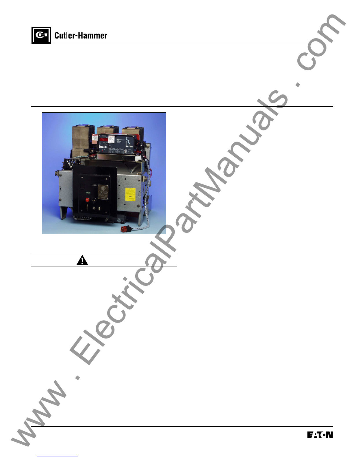
Eaton digtrip 510 with zone Interlock, Digitrip 510 basic, digtrip 610, digtrip 910, digtrip 810 Installation, Operation And Maintenance Manual
SAFETY PRECAUTIONS
www . ElectricalPartManuals . com
WARNING
POWER CIRCUIT BREAKERS ARE EQUIPPED
WITH HIGH SPEED, HIGH ENERGY OPERATING
MECHANISMS. THE BREAKERS AND THEIR
ENCLOSURES ARE DESIGNED WITH SEVERAL
BUILT-IN INTERLOCKS AND SAFETY FEATURES INTENDED TO PROVIDE SAFE AND
PROPER OPERATING SEQUENCES. TO PROVIDE MAXIMUM PROTECTION FOR PERSONNEL ASSOCIATED WITH THE INSTALLATION,
OPERATION, AND MAINTENANCE OF THESE
BREAKERS, THE FOLLOWING PRACTICES
MUST BE FOLLOWED. FAILURE TO FOLLOW
THESE PRACTICES MAY RESULT IN DEATH,
PERSONAL INJURY, OR PROPERTY DAMAGE.
• Only qualified persons, as defined in the National
Electric Code, who are familiar with the installation
and maintenance of power circuit breakers and their
associated switchgear assemblies should perf orm
any work associated with these breakers.
IL 33-K2C-3
Page 1
Digitrip Retrofit System for the
ITE K-Line Breakers: K-1600
(Black or Red), KDON-1600
(Black or Red), and K-2000 (Red)
• Completely read and understand all instructions
before attempting any installation, operation,
maintenance, or modification of these breakers.
• Always turn off and lock out the power source
feeding the breaker prior to attempting any
installation, maintenance, or modification of the
breaker. Do not use the circuit breaker as the
sole means for isolating a high voltage circuit.
Follow all lockout and tagging rules of the
National Electric Code and all other applicable
codes, regulations, and work rules.
• Do not work on a closed breaker or a breaker with
the closing springs charged. Trip (open) the breaker
and be sure the stored energy springs are
discharged before perf orming any work. The
breaker may trip open or the charging springs may
discharge, causing crushing or cutting injuries.
• For draw out breakers, trip (open), and then remove
the breaker to a well-lit work area before beginning
work.
• Do not perform any maintenance: including breaker
charging, closing, tripping, or any other function
which could cause significant movement of the
breaker while it is on the extension r ails. Doing so
may cause the breaker to slip from the rails and fall,
potentially causing severe personal injury to those
in the vicinity.
• Do not leave the breaker in an intermediate
position in the switchgear cell. Always leave it
in the connected, disconnected, or (optional)
test position. Failure to do so could lead to
improper positioning of the breaker and
flashover, causing death, serious personal
injury, and / or property damage.
• Do not defeat any safety interlock. Such
interlocks are intended to protect personnel and
equipment from damage due to flashover and
exposed contacts. Defeating an interlock could
lead to death, severe personal injury, and / or
property damage.
Effective 10/00
IL 33-K2C-3
www . ElectricalPartManuals . com
Digitrip Retrofit System for the
ITE K-Line Breakers: K-1600
(Black or Red), KDON-1600
(Black or Red), and K-2000 (Red)
CONTENTS
Page 2
Description
Introduction .......................................................... 4
Before Beginning the Retrofit Process
Identify the Breaker and the Retrofit Kit ................ 5
Following the Icons to a Successful Retrofit ......... 5
Step 1: General Breaker Preparation .............. 6
Step 2: Preparing the Breaker for
Retrofitting ............................................ 7
Step 3: Drilling the Breaker Angles ................. 8
Step 4: Preparing the DTA Assembly for
Installation ............................................ 9
Step 5: Installing the DTA Assembly in
the Breaker ......................................... 11
Step 6: Installing the Breaker Mounted
CPT on the DTA Mounting Angle ...... 13
Step 7: Final DTA and Reset
Installation and Adjustment .............. 17
Step 8: Installing the Copper Connectors .... 20
Step 9: Preparing the Trip Unit Assembly ....21
Step 10: Installing the Trip Unit on the
Breaker .............................................. 23
Step 11: Final Connection of the PT
and / or HV Wires ............................. 24
Step 12: Installing the Sensors ................ 27, 28
Step 13: Connecting the Sensor Harness
and the DTA Harness ....................... 29
Step 14: Connecting the External Harness
and Optional Components .............. 31
Step 15: Testing the Breaker .......................... 33
Step 16: Mounting the Cell Harness.............. 34
Step 17: Installing the Retrofitted Breaker in
the Cell .............................................. 34
Figures
1 Original Electromechanical Trip Units ............ 7
2. Removing the Glastic Moldings ..................... 7
3. Drilling Plan “A” – Front View ......................... 8
4. Optional Drilling Plan”A” ................................ 8
5. Drilling Plan “B” – Front View ......................... 9
6. Overview – DTA Assembly ............................. 9
7. Optional DTA Mounting Location ................... 9
8. DTA Mounted to the DTA Mounting Angle... 10
9. Connections at the 2- Point Terminal
Block ............................................................ 10
10. Location of the DTA Insulation Plate
Mounting Bracket......................................... 10
11. Auxiliary Switch Assembly ........................... 10
12. Correct Installation of the Auxiliary Switch
Assembly...................................................... 11
13. Overview – DTA Assembly installed in the
Breaker ......................................................... 11
14. Installing the DTA Assembly ........................ 12
15. Correct Wiring Harness Position .................. 12
16. Spacers Installed with the DTA Assembly ... 12
17. Routing of the DTA Extension Harness ........ 13
18. Overview – CPT Installed in the Breaker ..... 13
19. CPT Orientation and Screw Location .......... 14
20. Bracket Mounted to the CPT Insulation
Barrier........................................................... 14
Effective 10/00
21. Identification of the Line and Load Side
www . ElectricalPartManuals . com
HV Wires ...................................................... 14
22. Routing of the HV Wires ............................... 15
23. CPT Harness and HV Wires connected
to the CPT .................................................... 15
24. CPT Mounted to the DTA Assembly ...........16
25. CPT Mounting Screw Location .................... 16
26. Insulation Plate Mounted to the CPT ........... 16
27. Supplied CPT Voltage Labels ...................... 16
28. Overview – DTA and Reset Adjustment ....... 17
29. DTA Trip Plate Installed on the DTA Shaft.... 17
30. Setting the DTA Gap .................................... 18
31. Mounting the DTA Insulation Plate –
K-2000 Breakers Only .................................. 18
32. Connecting the Auxiliary Switch
Drive Link ..................................................... 18
33. Reset Rod Assembly.................................... 19
34. Correct Connection of the Reset Rod
Assembly and the Auxiliary Switch Drive
Link ............................................................... 19
35. Reset Rod Assembly Mounted in the
Breaker ......................................................... 19
36. Adjusting the Reset Rod Assembly ............. 20
37. Overview – Installation of the New
Copper Connectors ..................................... 20
38. Copper Connectors for the K-1600 / 2000
Breakers .......................................................20
38. Overview – Trip Unit Assembly .................... 21
39. Glass Poly Barrier Mounted to the Aux.
CT Module ................................................... 21
40. PT Module Mounted to the Glass Poly
Barrier........................................................... 22
41. Correct Installation of the Support Clips ..... 22
42. Overview – Trip Unit Assembly Installed
on the Breaker.............................................. 23
43. Installing the Trip Unit Assembly
Mounting Brackets ....................................... 23
44. Connecting the Aux. CT Harness ................ 24
45. Overview – Final Routing of the PT and
HV Wires ...................................................... 24
46. Correct Position of the Insulated Tubing ..... 25
IL 33-K2C-3
Page 3
47. PT Wires Connected to the
Breaker Stags .............................................. 25
48. Correct Position of the Insulated Tubing
and HV Fuses ............................................... 26
49. HV Wires Connected to the Top
Breaker Stabs .............................................. 26
50. Overview – Installed Top Mounted
Sensors ........................................................ 27
51. Securing the Sensor Assembly to the
Breaker ......................................................... 27
52. K-2000 Sensors Installed ............................. 27
53. Overview – Installed Bottom Mounted
Sensor .......................................................... 28
54. Drilling Plan “C” ............................................ 28
55. Securing the Sensor Mounting Platform ...... 29
56. Overview – Installing the Sensor and
DTA Harness ............................................... 29
57. Connecting the DTA Harness ....................... 30
58. Connecting the Sensor Harness ..................30
59. Routing of the Sensor Harness .................... 30
60. Sensor Harness Connected to the Top
Mounted Sensors ......................................... 31
61. Sensor Harness Connected to the
Bottom Mounted Sensors ............................ 31
62. 510 Basic Kit External Harness Plug ........... 31
63. Overview – Connecting the External
Harness ........................................................ 31
64. Securing the External Harness .................... 32
65. Connecting the Auxiliary Switch .................. 32
66. Location of the Wire Tie ............................... 32
67. Retrofit Components .................................... 40
Tables
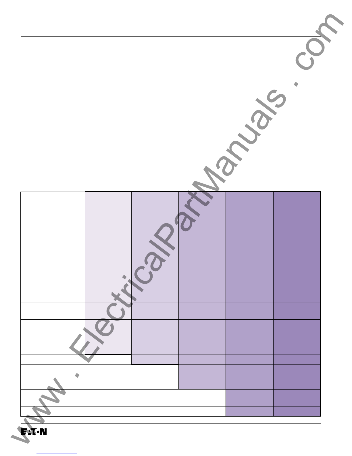
1. Available Retrofit Kits ..................................... 4
2. Identifying the K-Line Breaker ....................... 5
3. CPT Voltage Taps ......................................... 15
4. Sensor Taps Ratings .................................... 30
5. Torque Values for General Mounting and
Screw Size Conversion ................................ 39
6. Torque Values for Copper BUS
Connectors................................................... 39
Effective 10/00
Page 4
www . ElectricalPartManuals . com
IL 33-K2C-3
INTRODUCTION
Cutler-Hammer Digitrip Retrofit Kits are available in
a number of configurations that provide a wide
range of features. The Digitrip System starts with
the 510 Basic Kit which offers true RMS sensing,
overcurrent protection, and self-testing features.
Advanced Digitrip Retrofit Kits feature zone
interlocking, digital alphanumeric displays, remote
alarm signals, PowerNet communications, energy
monitoring capabilities, power factors, and
harmonic content measurements.
The following table provides a quick reference of
the components supplied with each level of Retrofit
Kit. Before beginning the Retrofit process, take a
minute to review the information contained in the
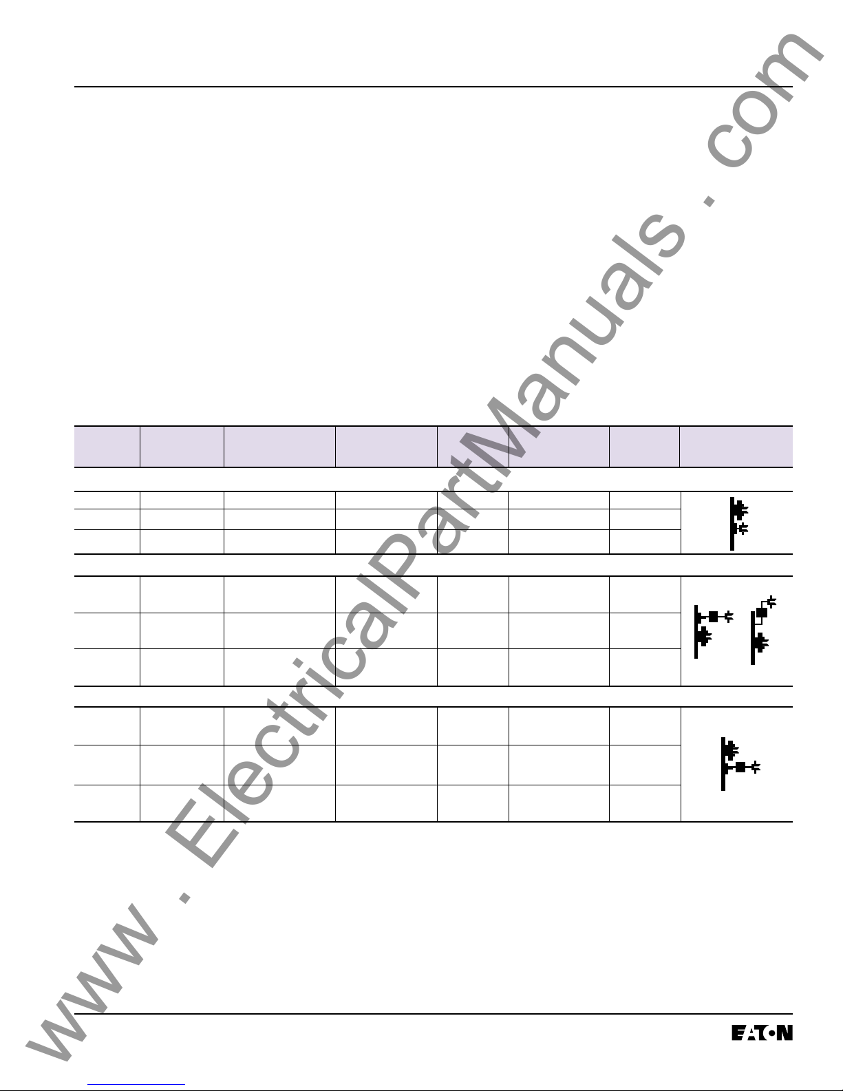
Table 1 Available Retrofit Kits
Components 510 Basic 510 with 610 810 910
Zone
Interlock
table. It is important that the Retrofitter
understands which level of Retrofit Kit is to be
installed and which components are included with
the Kit. The instructions contained in this manual
cover the installation of all levels of Retrofit Kit. If
the Kit you are installing does not contain a certain
component, skip the instructions for that
component and proceed to the next.
Throughout the Retrofit process, refer to the Torque
Tables at the back of this manual for specific
torque values.
If you have any questions concerning the Retrofit
Kit and / or the Retrofit process, contact
Cutler-Hammer at: 1-800-937-5487.
Trip Unit
Rating Plug
Auxiliary Current
Transformer
(CT) Module
Auxiliary
CT Harness
Sensors
Sensor Harness
Direct Trip
Actuator (DTA)
Mounting Brackets
and Hardware
External Plug 1 Connector 2 Connector 4 Connector 4 Connector
Harness Harness Harness Harness Harness
Cell Harness
Breaker Mounted
Control Power
Transformer (CPT)
Potential Transformer
(PT) Module
Auxiliary Switch
Effective 10/00
IL 33-K2C-3
www . ElectricalPartManuals . com
Page 5
Before Beginning the Retrofit Process
Identify the Breaker and the Retrofit Kit
Please refer to the following table and verify that
the first three (3) characters of the Retrofit Kit
Code Number correspond to the Breaker being
It is important to verify exactly which version of ITE
Retrofitted.
K-Line Breaker(s) is to be Retrofitted and to insure
that the correct Cutler-Hammer Retrofit Kit(s) was
Following the Icons to a Successful Retrofit
ordered. Each Breaker must be identified using all
of the following sources:
During certain parts of the Retrofit Process, procedures may differ depending on the version of the
1. Name Plate Information;
2. Back Plate Color;
3. Type of Finger Clusters
(Rectangular or Round); and
4. Fuse Use and Configuration
Breaker being Retrofitted. To enable the Retrofitter
to quickly identify the correct procedures for the
Breaker, Icon(s) will appear. Simply follow only the
instructions identified by the Icon for the Breaker
being Retrofitted.
(Horizontal or Vertical).
Table 2 Identifying the K-Line Breaker
Breaker Back Plate Desired Sensor Finger Cluster Fuse Fuse Retrofit ICON
Rating Color
Non-Fused
K-1600 Black Top Rectangular None N.A. K1C
K-1600 Red Top Rectangular None N.A. K2C
K-2000 Red Top Round None N.A. K2D
1
Location Type Location Configuration Kit Code
Top Mounted Horizontal and Vertical Fused
KDON- Black
1600 or Vertical
KDON- Red Bottom Rectangular To p Horizontal K4C
1600 or Vertical
KDON- Red Bottom Round Top Horizontal K7C
1600 or Vertical
Bottom Mounted Horizontal Fused
KDON- Black
1600
KDON- Red Top Rectangular Bottom Horizontal K2C
1600
KDON- Red Top Round Bottom Horizontal K5C
1600
NOTES: 1. Black or Red refers to the color of the Breaker Back Plate.
GENERAL NOTE: If the existing Breaker components mandate that the new DTA, supplied with the Retrofit Kit, be mounted inside the
2
2
2. If specified during ordering, special Trip Unit Brackets have been supplied for some older models of the
KDON-1600 Black Breaker equipped with trigger fuses. If the Brackets are needed but were not ordered,
contact Cutler-Hammer at: 1-800-937-5487.
Breaker on the right side instead of the left, as detailed in these instructions, contact Cutler-Hammer at: 1-800-937-5487
to obtain the special parts required. See Step 4 for details.
Bottom Rectangular Top Horizontal K6C
Top Rectangular Bottom Horizontal K1C
Effective 10/00
Page 6
www . ElectricalPartManuals . com
IL 33-K2C-3
STEP 1: GENERAL BREAKER PREPARATION
Before attempting to remove the Breaker from the
Cell or perform any Retrofit operation, be sure to
read and understand the Safety Precautions
section of this manual. In addition, be sure to read
and understand the Instructions for the Application
of Digitrip RMS Retrofit Kits on Power Circuit
Breakers (Retrofit Application Data – Publication
AD-33-855-2), supplied with the Digitrip Retrofit
Kit.
WARNING
DO NOT ATTEMPT TO INSTALL OR PERFORM
MAINTENANCE ON EQUIPMENT WHILE IT IS
ENERGIZED. SEVERE PERSONAL INJURY OR
DEATH CAN RESULT FROM CONTACT WITH
ENERGIZED EQUIPMENT. VERIFY THAT NO
VOLTAGE IS PRESENT BEFORE PROCEEDING.
A. Trip the Breaker and remove it from the Cell.
Move the Breaker to a clean, well-lit work
bench.
To begin the Retrofit Process, refer to the components list at the end of this manual. Lay out the
components and hardware according to the steps
outlined. The parts bags are labeled with the
corresponding step number. The components and
hardware will be used to complete each step in the
Retrofit Process.
NOTE: It is the responsibility of the Retrofitter to
insure that the Breaker and all original
components are in good condition. Visually inspect all Breaker components for
signs of damage or wear. If any signs of
damage or wear are detected for components not included in the Retrofit Kit,
secure the necessary replacement parts
before beginning the Retrofit Process.
The force necessary to trip the Breaker
should not exceed three (3) lbs.
NOTE: It is the responsibility of the Retrofitter to
insure that the proper, manufacturer’s
recommended crimping tools and terminals are used for each type of connector.
It is also the responsibility of the
Retrofitter to insure that all wire
preparations, connections, strippings,
terminations, and wiring techniques are
performed according to the latest IEEE,
NEC, and / or NEMA industry standards,
specifications, codes, and guidelines.
Effective 10/00
IL 33-K2C-3
www . ElectricalPartManuals . com
STEP 2: PREPARING THE BREAKER FOR
RETROFITTING
Page 7
Refer to the ITE K-Line Instruction Manual, originally supplied with the Breaker, to perform the
following procedures.
NOTE: For all photographs contained within this
manual, an ITE K-1600 Black Breaker
(without blown fuse indicators) was used
as the subject. Depending on the version
and age of the Breaker being Retrofitted,
some components / views may differ from
those depicted in the manual.
Note the orientation of the existing fuses.
Follow the ITE K-1600 / 2000 Instruction
Manual, originally supplied with the Breaker,
and remove the fuses, fuse mountings, and
associated hardware from the bottom Breaker
Stabs. Set all parts aside for reinstallation later
in the Retrofit Process.
C. Remove the four (4) screws securing each
bottom Glastic Molding to the Breaker.
D. Remove the four (4) screws securing each of
the three (3) copper pieces to the Breaker Pole
Assemblies.
E. Remove the Glastic Moldings, with the at-
tached Electromechanical Trip Units, from the
Breaker.
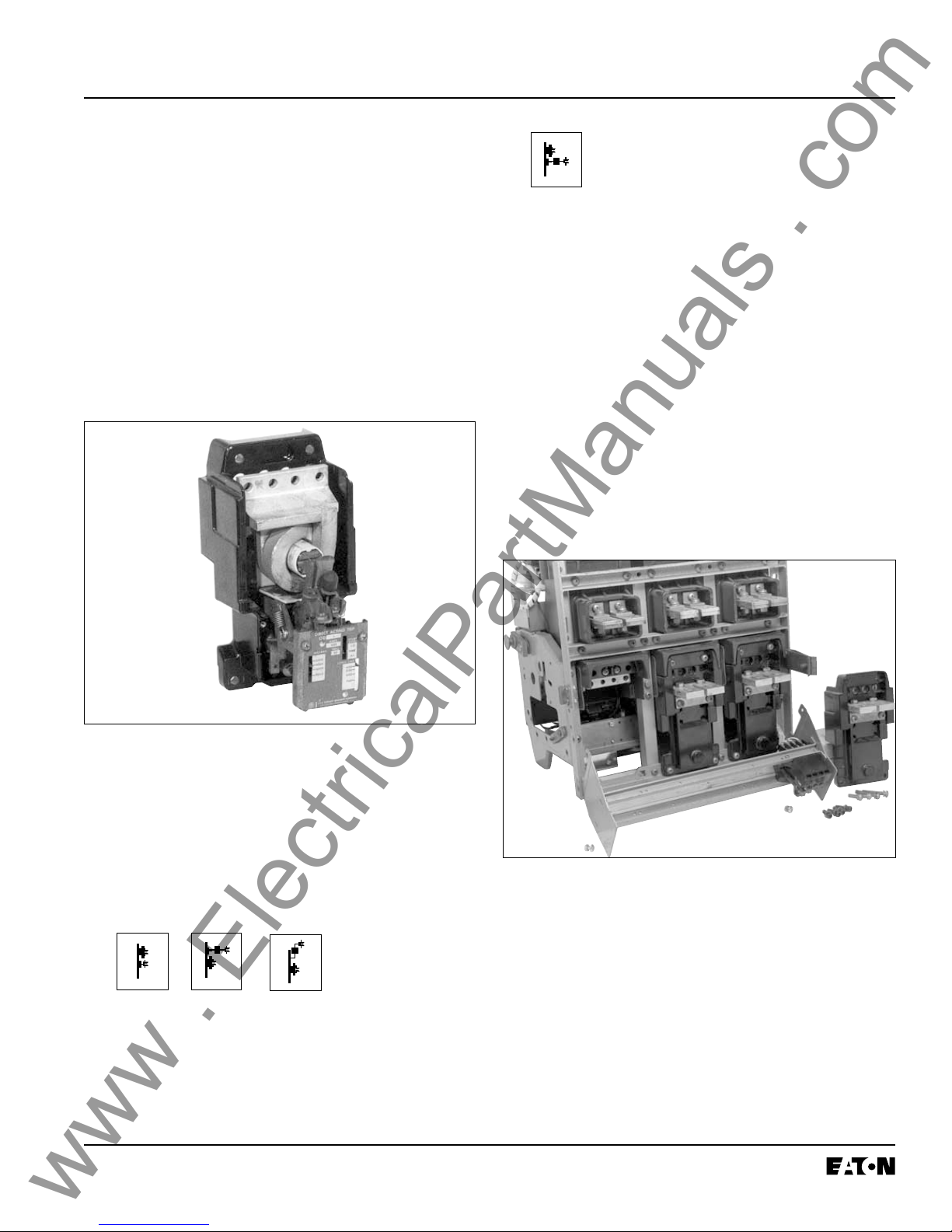
Fig. 1 Original Electromechanical Trip Unit
A. For Breakers equipped with a Secondary
Contact Bracket, move the back of the Breaker
near the edge of the work bench. Remove the
two (2) screws securing the top of the Secondary Contact Bracket. Loosen the two (2)
bottom screws then rotate the bracket down
over edge of work bench
B.
Remove the retaining clips then the pins securing the Finger Clusters to the Bottom Breaker
Stabs. Remove the Finger Clusters. Set all
parts aside for reinstallation later in the Retrofit
Process.
Effective 10/00
Fig. 2 Removing the Glastic Moldings
F. Working from the rear of the assembly, remove
the Electromechanical Trip Units by carefully
drilling out the four (4) .190" screws that secure
each Trip Unit to the Molding.
G. Remove the two (2) screws securing the Cop-
per Extensions then remove the Trip Unit from
each Molding.
Page 8
www . ElectricalPartManuals . com
IL 33-K2C-3
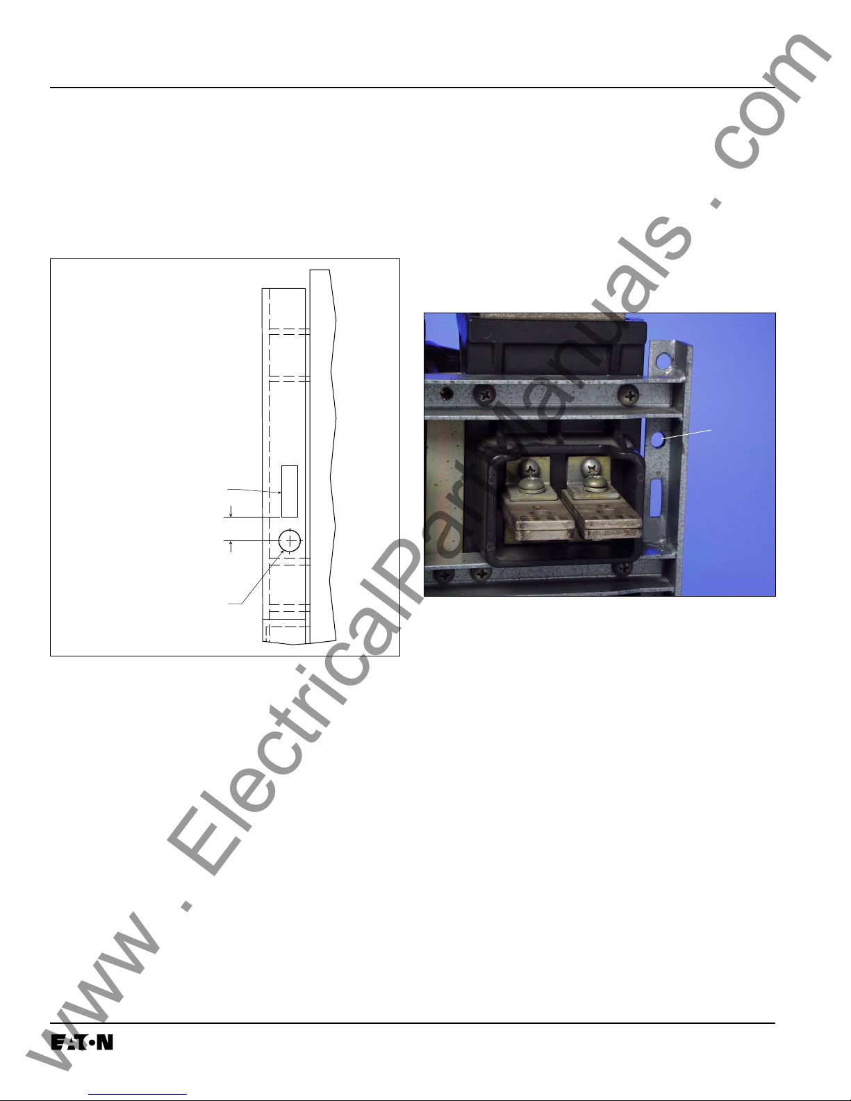
STEP 3: DRILLING THE BREAKER ANGLES
A. Working from the rear of the Breaker and using
a .500" drill bit, drill a hole in the left Breaker
Angle (See Drilling Plan “A”). This hole will be
used later in the Retrofit Process when installing the Sensor Harness.
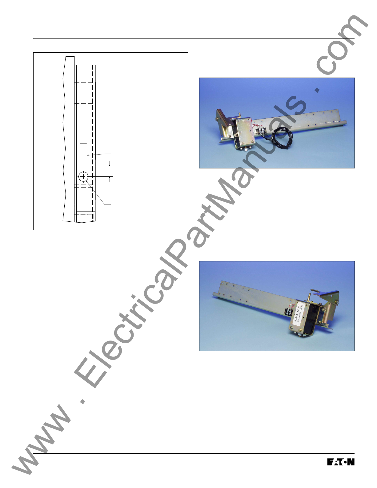
FRONT
VIEW
EXISTING SLOT
NOTE: The hole should be drilled slightly below
the Breaker Cross Rail and be located so
as not to interfere with the Lifting Rack
when installed.
After Retrofitting, care should be taken
when installing the Lifting Rack so that
any new wires or harnesses that pass
through the rear Breaker Angles are not
damaged.
DRILL
.500"
HOLE
.50"
.500" DIA. (1) FOR
SENSOR HARNESS
(ALL KITS)
Fig. 3 Drilling Plan “A” - Front View
NOTE: On some versions of the K-1600 / 2000
Breakers, the hole for the Sensor Harness
can not be drilled where indicated in
Drilling Plan “A”. If this is the case with
the Breaker Being Retrofitted, follow the
instructions in Step 3-B.
B. For Use on Some Versions: Working from the
rear of the Breaker and using a .500" drill bit,
drill a hole in the left Breaker Angle, directly
below the top Breaker Cross Rail (See Fig. 4).
This hole will be used later in the Retrofit
Process when installing the Sensor Harness.
Fig. 4 Optional Drilling Plan “A”
For Kits Supplied with a PT Module and / or
Breaker Mounted CPT Only.
C. Working from the rear of the Breaker and using
a .500" drill bit, drill a hole in the right Breaker
Angle (See Drilling Plan “B”). This hole will be
used later in the Retrofit Process when installing the PT and / or HV Wires.
Effective 10/00
IL 33-K2C-3
www . ElectricalPartManuals . com
Page 9
STEP 4: PREPARING THE DTA ASSEMBLY
FOR INSTALLATION
FRONT
VIEW
EXISTING SLOT
.50"
.500" DIA. (1) FOR
HV AND / OR
PT WIRES
Fig. 5 Drilling Plan “B” - Front View
NOTE: On some versions of the K-1600 / 2000
Breakers, the hole for the PT and / or HV
Wires can not be drilled where indicated in
Drilling Plan “B”. If this is the case with
the Breaker Being Retrofitted, follow the
instructions in Step 3-D.
D. For Use on Some Versions: Working from the
rear of the Breaker and using a .500" drill bit,
drill a hole in the right Breaker Angle, directly
below the top Breaker Cross Rail (similar to the
hole for the Sensor Harness drilled in Step
3-B). This hole will be used later in the Retrofit
Process when connecting the PT and / or HV
Wires.
Fig. 6 Overview - DTA Assembly
NOTE: If an existing Breaker component does not
allow the DTA to be mounted on the right
side of the Breaker (when viewed from the
rear of the Breaker), a left hand DTA
mounting kit is available. For details and
to acquire the necessary parts, contact
Cutler-Hammer at: 1-800-937-5487.
Fig. 7 Optional DTA Mounting Location
A. Apply Loc-Tite
the DTA Bearing Plate to the DTA Bearing Plate
Mounting Bracket, as shown, using the (2)
.164-32 × .312" pan lock screws and (2) flat
washers supplied.
®
243 to the threads then mount
Effective 10/00
Page 10
www . ElectricalPartManuals . com
B. Apply Loc-Tite® 243 to the threads then mount
the DTA and the DTA Bearing Plate Assembly
to the DTA Mounting Angle, as shown, using
the (2) .164-32 × .312" pan lock screws, (2)
.164-32 × .500" pan screws, (2) lock washers,
and (4) flat washers supplied.
NOTE: Insure that the DTA Shaft moves freely
after mountng. If not, reposition the
mounting hardware.
IL 33-K2C-3
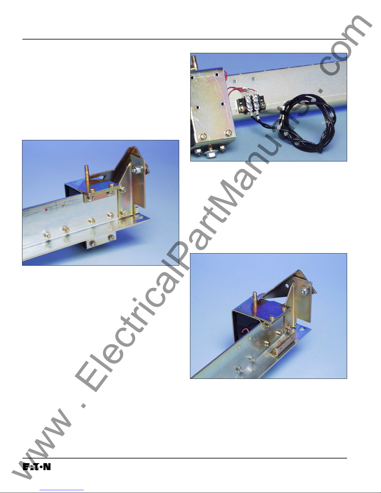
Fig. 9 Connections at the 2-Point Terminal Block
D. For K-2000 Breakers Only: Mount the DTA
Insulation Plate Mounting Bracket to the DTA
Assembly, as shown, using the (2) .164-32 ×
.625" screws, (4) flat washers, (2) lock washers,
and (2) nuts supplied. Note that the nonthreaded holes in the Mounting Bracket are
used to secure the Mounting Bracket to the
DTA Assembly.
Fig. 8 DTA Mounted to the DTA Mounting Angle
C. Connect the DTA Wires to the two (2) top
terminals of the 2-Point Terminal Block. Connect the DTA Extension Harness to the two (2)
bottom terminals of the 2-Point Terminal Block.
Connect the “+” wire to the same terminal as
the “+” wire from the DTA. Connect the
unmarked wire to the same terminal as the
unmarked wire from the DTA.
Fig.10 Location of the DTA Insulation Plate
Mounting Bracket
Effective 10/00
IL 33-K2C-3
www . ElectricalPartManuals . com
Page 11
E. For Kits Supplied with an Auxiliary Switch Only:
Cut .250" from the end of the Microswitch Arm.
Mount the Microswitch the to Auxiliary Switch
Mounting Bracket, as shown, using the (2)
.138-32 × 1.00" screws, (4) flat washers, (2)
lock washers, and (2) nuts supplied.
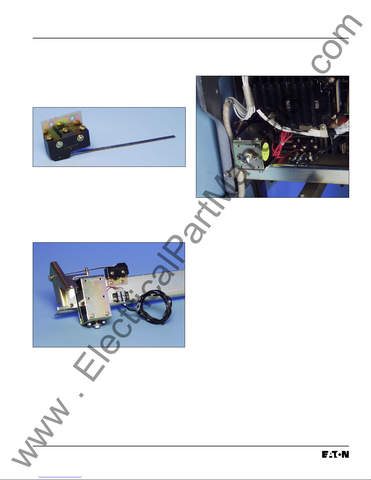
Fig. 11 Auxiliary Switch Assembly
F. Mount the Auxiliary Switch Assembly to the
DTA Assembly, as shown, using the (2) .138-32
× .375" screws, (4) flat washers, (2) lock washers, and (2) nuts supplied. Note that the
Microswitch Arm must extend through the hole
in the DTA Reset Arm.
STEP 5: INSTALLING THE DTA ASSEMBLY IN
THE BREAKER
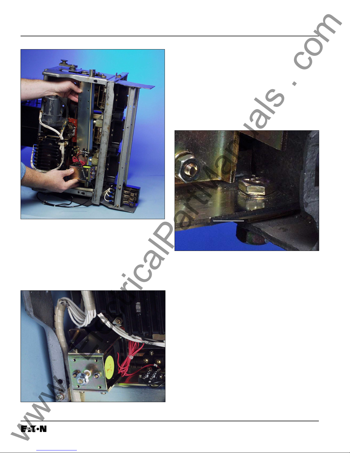
Fig.13 Overview – DTA Assembly installed in the
Breaker
A. Carefully lay the Breaker on its left side.
Fig. 12 Correct Installation of the Auxiliary Switch
Assembly
B. Working from the bottom of the Breaker, drill a
.312" diameter hole in each of the bottom
Breaker Flanges 1.75" from the Breaker Back
Plate. Insure that no metal shavings fall into
the Breaker during the drilling process.
C. Insert the DTA Assembly into the Breaker and
align the holes in the DTA Mounting Angle with
the holes just drilled in Step 5-B. Note that it is
necessary for the DTA Assembly to slightly
protrude through the window in the right side
of the Breaker to achieve proper alignment.
Effective 10/00
Page 12
www . ElectricalPartManuals . com
IL 33-K2C-3
E. Return the Breaker to its upright position.
Verify that there is clearance between the
bottom of the DTA Shaft and the work bench.
If not, turn the Breaker back on its side, remove the mounting hardware securing the DTA
Assembly to the Breaker. Use one (1) or two
(2) of the supplied spacers on each side, as
required, to raise the DTA Assembly. Using the
hardware just removed, again temporarily
mount the DTA Assembly to the Breaker.
Fig. 14 Installing the DTA Assembly
D. Temporarily mount the DTA Assembly on the
inside of the bottom Breaker Flanges using the
(2) .250-20 × .750" bolts, (4) flat washers, (2)
lock washers, and (2) nuts supplied. Note that
the existing wiring harness must be below the
DTA Assembly.
SPACERS
Fig. 16 Spacers Installed with the DTA Assembly
Return the Breaker to its upright position and
verify that there is clearance between the
bottom of the DTA Shaft and the work bench.
If clearance exists, tighten the DTA Assembly
mounting hardware.
NOTE: If proper clearance can not be achieved
by using the spacers provided, or if proper
Trip and Reset functioning can not be
achieved with the spacers installed, the
DTA Shaft may be carefully cut to provide
the proper clearance.
For Kits Supplied with a Breaker Mounted CPT
Only: Do not tighten the DTA Assembly mount-
ing hardware at this time. This hardware will be
tightened after the Breaker Mounted CPT is
installed in Step 6.
Fig. 15 Correct Wiring Harness Position
Effective 10/00

IL 33-K2C-3
www . ElectricalPartManuals . com
Page 13
F. Route the DTA Extension Harness up through
the Breaker, then through the existing hole in
the Breaker Platform. Insure that the DTA
Extension Harness is clear of all moving parts
within the Breaker.
For Kits Supplied with a Breaker Mounted CPT
Only.
STEP 6: INSTALLING THE BREAKER
MOUNTED CPT ON THE DTA
MOUNTING ANGLE
Fig. 17 Routing of the DTA Extension Harness
Fig. 18 Overview – CPT Installed in the Breaker
NOTE: If a left-hand mounting kit was used to
install the DTA on the DTA Mounting Angle
in Step 4, the Breaker Mounted CPT can
not be installed on the DTA Assembly as
detailed in the following steps. The CPT
will have to be mounted either in another
location on the Breaker or in the Breaker
Cell. Alternative mounting of the CPT is
the sole responsibility of the Retrofitter.
NOTE: On some versions of the K-1600 / 2000
Breakers originally supplied with a Breaker
Interlock Mechanism, the Breaker
Mounted CPT can not be installed on the
DTA Assembly as detailed in the following
steps. The CPT will have to be mounted
either in another location on the Breaker
or in the Breaker Cell. Alternative mounting of the CPT is the sole responsibility of
the Retrofitter.
Effective 10/00
Page 14
www . ElectricalPartManuals . com
IL 33-K2C-3
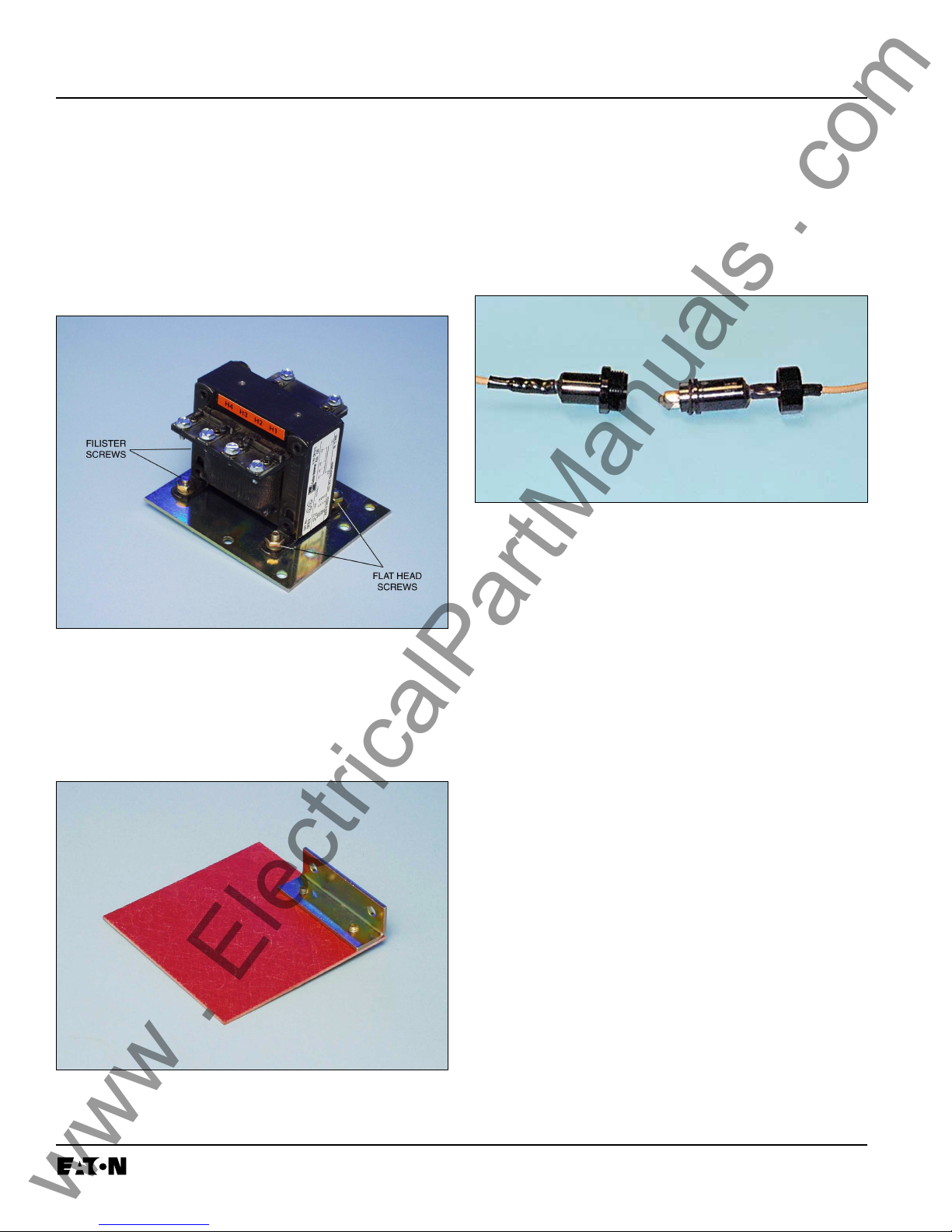
A. Mount the Breaker Mounted CPT to the
CPT Mounting Plate, as shown, using the
(2) .190-32 × .500" flat head screws, (2) .19032 × .500" filister head screws, (6) flat washers,
(4) lock washers, and (4) nuts supplied. Note
the orientation of the CPT to the holes in the
Mounting Plate. The CPT must be mounted in
this position.
Fig. 19 CPT Orientation and Screw Location
B. Attach the CPT Insulation Barrier to the CPT
Insulation Barrier Mounting Bracket, as shown,
using the (2) .164-32 × .312" pan lock screws
and (2) flat washers supplied.
NOTE: The High Voltage (HV) Wires have a LOAD
Side and a LINE Side. The HV Wires must
be installed in the correct orientation
during the following procedure. For the
purpose of identification, the words “Load
Side” are marked on the female fuse
receptacle of each HV Wire.
LINE SIDE
Fig. 21 Identification of the Line and Load Side
HV Wires
NOTE: The Load Side HV Wires are longer than
necessary and are cut during the following
steps. Before cutting the wires, insure
that sufficient length is left so that the
connections can be made to the correct
terminals on the CPT.
C. Route the Load Side HV Wires and the CPT
Harness through the existing hole in the
Breaker Platform, then down to the bottom
right corner of the Breaker. Note that the final
location of the HV Fuses will be along the right
side of the Breaker. Note also that the CPT
Harness will be connected to the new Trip Unit
later in the Retrofit Process. Insure that, when
cutting the HV Wires and CPT Harness in the
following steps, sufficient length is left for these
connections to be made.
LOAD SIDE
Fig. 20 Bracket Mounted to the CPT Insulation
Barrier
Effective 10/00
 Loading...