

Eaton Digitrip RMS 910 Instruction Leaflet
Instruction Leaflet I. L. 29-889B
Effective June 2011
Supersedes I.L. 29-889A 5/97
Instructions for Digitrip RMS 910 Trip Unit

Instruction Leaflet I. L. 29-889B
Effective June 2011
Instructions for Digitrip RMS 910 Trip Unit
Contents
Description Page
Important Safety Instructions . . . . . . . . . . . . . . . . . . . . . . . . . . . . . .4
1 General Description - Digitrip RMS 910
Trip Unit . . . . . . . . . . . . . . . . . . . . . . . . . . . . . . . . . . . . . . . . . . . .4
1.1 Basic Digitrip RMS 910 Trip Unit . . . . . . . . . . . . . . . . . . . . . . .4
1.1.1 Operational Status and Protection TRIP Indicators . . . . . .5
1.1.2 General Over-Current Protection . . . . . . . . . . . . . . . . . . . .6
1.1.3 Discriminator (High Initial Current Release)
(For Types LS and LSG Trip Units Only) . . . . . . . . . . . . . . .9
1.1.4 OVERRIDE (Fixed Instantaneous) . . . . . . . . . . . . . . . . . . 10
1.1.5 Zone Interlocking . . . . . . . . . . . . . . . . . . . . . . . . . . . . . . . 10
1.2 Four Character Information Display Window . . . . . . . . . . . . . 10
1.2.1 Values Displayed During Normal Service . . . . . . . . . . . . 10
1.2.1.1 Instrumentation - Current Values . . . . . . . . . . . . . . . . .10
1.2.1.2 Instrumentation - Voltage Values . . . . . . . . . . . . . . . . . 12
1.2.1.3 Instrumentation - Power, Power Factor and Energy
Values . . . . . . . . . . . . . . . . . . . . . . . . . . . . . . . . . . . . . .13
1.2.1.4 Harmonics [THD] . . . . . . . . . . . . . . . . . . . . . . . . . . . . . 14
1.2.2 Messages Displayed After ALARM or TRIP . . . . . . . . . . 14
1.2.1.1 ROM Error ... See I.L. . . . . . . . . . . . . . . . . . . . . . . . . . . 15
1.3 Frame Rating, Sensor Rating (where applicable) and Rating
Plugs . . . . . . . . . . . . . . . . . . . . . . . . . . . . . . . . . . . . . . . . . . .15
1.4 Power / Relay Module . . . . . . . . . . . . . . . . . . . . . . . . . . . . . .16
1.5 Potential Transformer Module . . . . . . . . . . . . . . . . . . . . . . . . 16
1.6 Auxiliary Power Module . . . . . . . . . . . . . . . . . . . . . . . . . . . . . 17
2 UL Listed Devices . . . . . . . . . . . . . . . . . . . . . . . . . . . . . . . . . . . . 17
3 Protection Settings . . . . . . . . . . . . . . . . . . . . . . . . . . . . . . . . . . .18
3.1 General . . . . . . . . . . . . . . . . . . . . . . . . . . . . . . . . . . . . . . . . . 18
3.2 Long Delay Current Setting . . . . . . . . . . . . . . . . . . . . . . . . . . 18
3.3 Long Delay Time Setting . . . . . . . . . . . . . . . . . . . . . . . . . . . .18
3.4 Short Delay Current Setting . . . . . . . . . . . . . . . . . . . . . . . . . 18
3.5 Short Delay Time Setting . . . . . . . . . . . . . . . . . . . . . . . . . . .18
3.6 Instantaneous Current Setting . . . . . . . . . . . . . . . . . . . . . . . 18
3.7 No Instantaneous Current Setting . . . . . . . . . . . . . . . . . . . . 19
3.8 Ground Fault Current Setting . . . . . . . . . . . . . . . . . . . . . . . . 19
3.9 Ground Fault Time Delay Setting . . . . . . . . . . . . . . . . . . . . .19
4 Test Procedures . . . . . . . . . . . . . . . . . . . . . . . . . . . . . . . . . . . . . . 19
4.1 General . . . . . . . . . . . . . . . . . . . . . . . . . . . . . . . . . . . . . . . . . 19
4.2 When To Test . . . . . . . . . . . . . . . . . . . . . . . . . . . . . . . . . . . . .19
4.3 Testing Provisions . . . . . . . . . . . . . . . . . . . . . . . . . . . . . . . . .20
4.4 Conducting Tests . . . . . . . . . . . . . . . . . . . . . . . . . . . . . . . . . .20
4.4.1 Not Tripping the Breaker . . . . . . . . . . . . . . . . . . . . . . . . .21
4.4.2 Tripping the Breaker . . . . . . . . . . . . . . . . . . . . . . . . . . . .21
4.5 Testing the Back-up Battery (Inside the Rating Plug) . . . . . .21
4.5.1 Back-up Battery Check . . . . . . . . . . . . . . . . . . . . . . . . . .21
4.5.2 Replacing the Back-up Battery . . . . . . . . . . . . . . . . . . . .21
5 Communications . . . . . . . . . . . . . . . . . . . . . . . . . . . . . . . . . . . . .22
5.1 Trip Unit Address and Baud Rate . . . . . . . . . . . . . . . . . . . . .24
5.2 Remote Master Computer . . . . . . . . . . . . . . . . . . . . . . . . . .25
5.3 Assemblies Electronic Monitor (AEM-II) and Breaker
Interface Monitor (BIM) . . . . . . . . . . . . . . . . . . . . . . . . . . . . .25
5.4 Both Remote Master Computer and AEM / BIM . . . . . . . . .25
5.5 INCOM
5.6 Information Communicated by Digitrip RMS 910 . . . . . . . . .25
®
Network Interconnections . . . . . . . . . . . . . . . . . . .25
5.7 Waveform Capture . . . . . . . . . . . . . . . . . . . . . . . . . . . . . . . .25
5.8 Remote Closing and Tripping of Circuit Breakers . . . . . . . . .25
5.9 Remote Resetting of the Trip Unit . . . . . . . . . . . . . . . . . . . .26
6 References . . . . . . . . . . . . . . . . . . . . . . . . . . . . . . . . . . . . . . . . .26
6.1 Digitrip RMS Trip Assemblies . . . . . . . . . . . . . . . . . . . . . . . .26
6.2 Type DS Low-Voltage AC Power Circuit Breakers . . . . . . . . .26
6.3 Type DS II Low-Voltage AC Power Circuit Breakers . . . . . . .26
6.4 Type SPB Systems Pow-R . . . . . . . . . . . . . . . . . . . . . . . . . . .26
®
6.5 Series C
R-Frame Molded Case Circuit Breakers . . . . . . . .27
6.6 Assemblies Electronic Monitors . . . . . . . . . . . . . . . . . . . . . .27
®
6.7 INCOM
AND IMPACC® COMMUNICATIONS . . . . . . . . . . .27
APPENDIX A: Zone lnterlocking . . . . . . . . . . . . . . . . . . . . . . . . . . .28
APPENDIX B: Interpreting Display Codes after Circuit Breaker
Trips . . . . . . . . . . . . . . . . . . . . . . . . . . . . . . . . . . . . .29
2
EATON CORPORATION www.eaton.com

Instructions for Digitrip RMS 910 Trip Unit
Instruction Leaflet I. L. 29-889B
Effective June 2011
List of Figures
Description Page
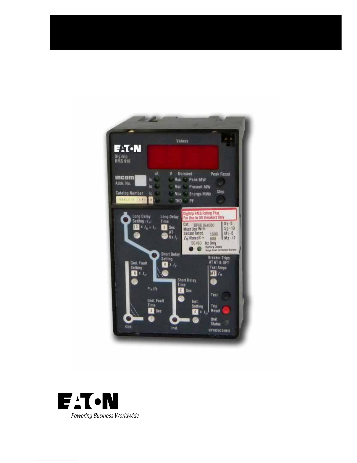
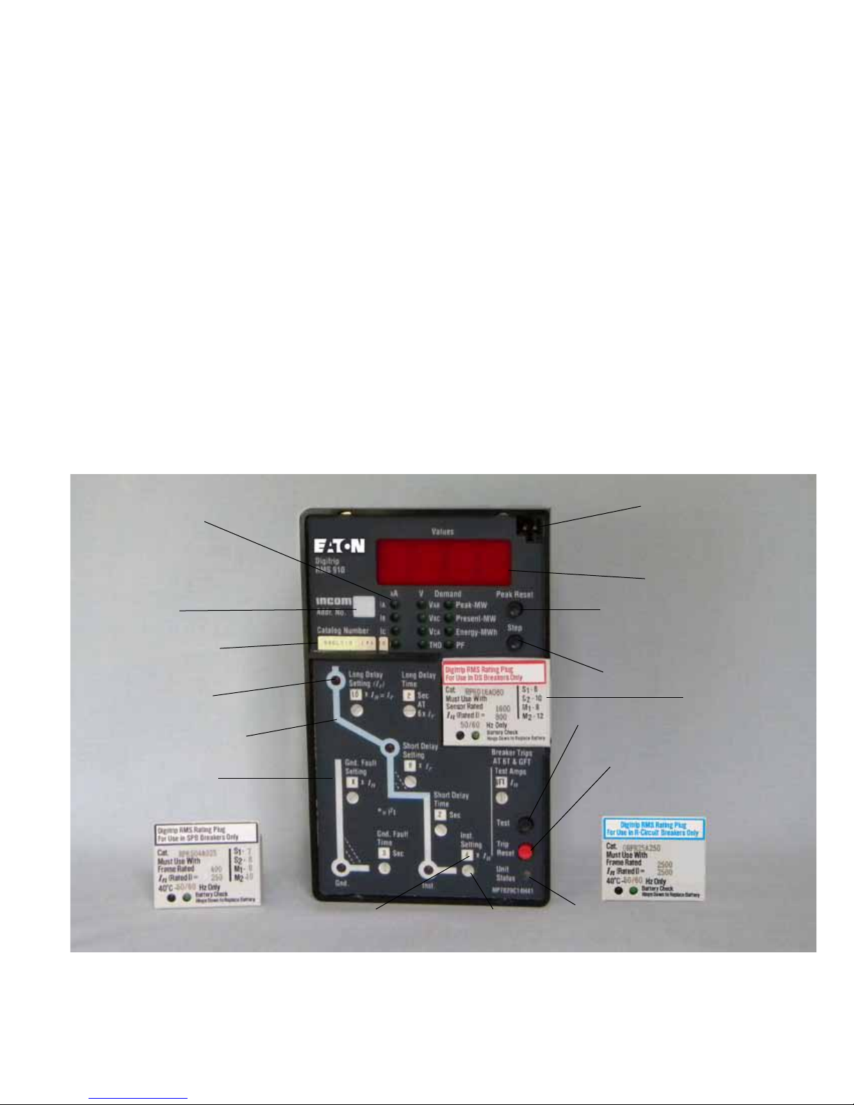
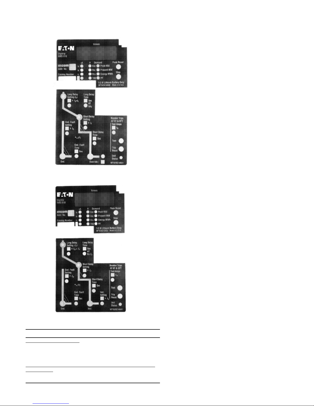
Figure 1. Digitrip RMS 910 Trip Unit Type LSIG with Rating Plug. . . . 5
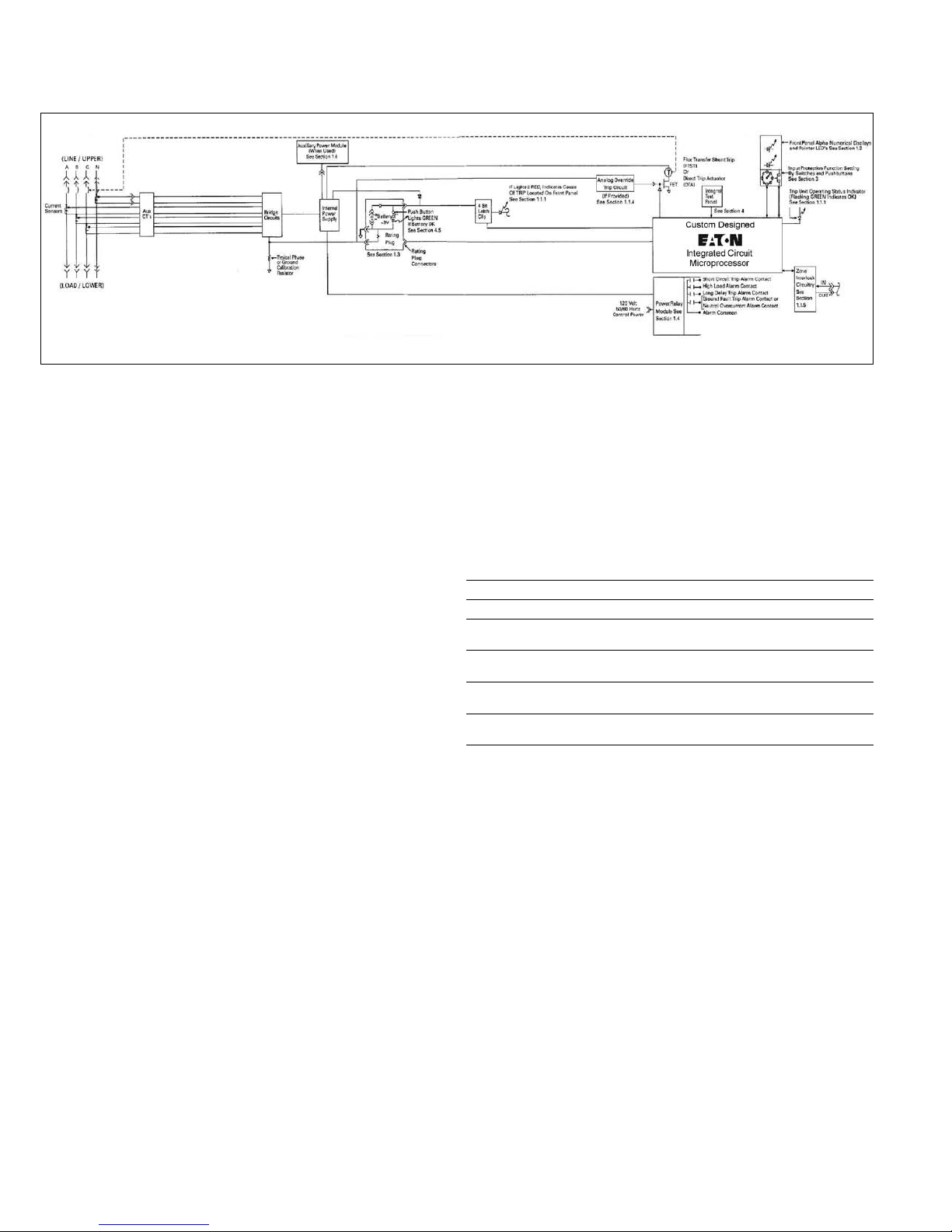
Figure 2. RMS Digitrip 910 Trip Unit - Block Diagram. . . . . . . . . . . . . 6
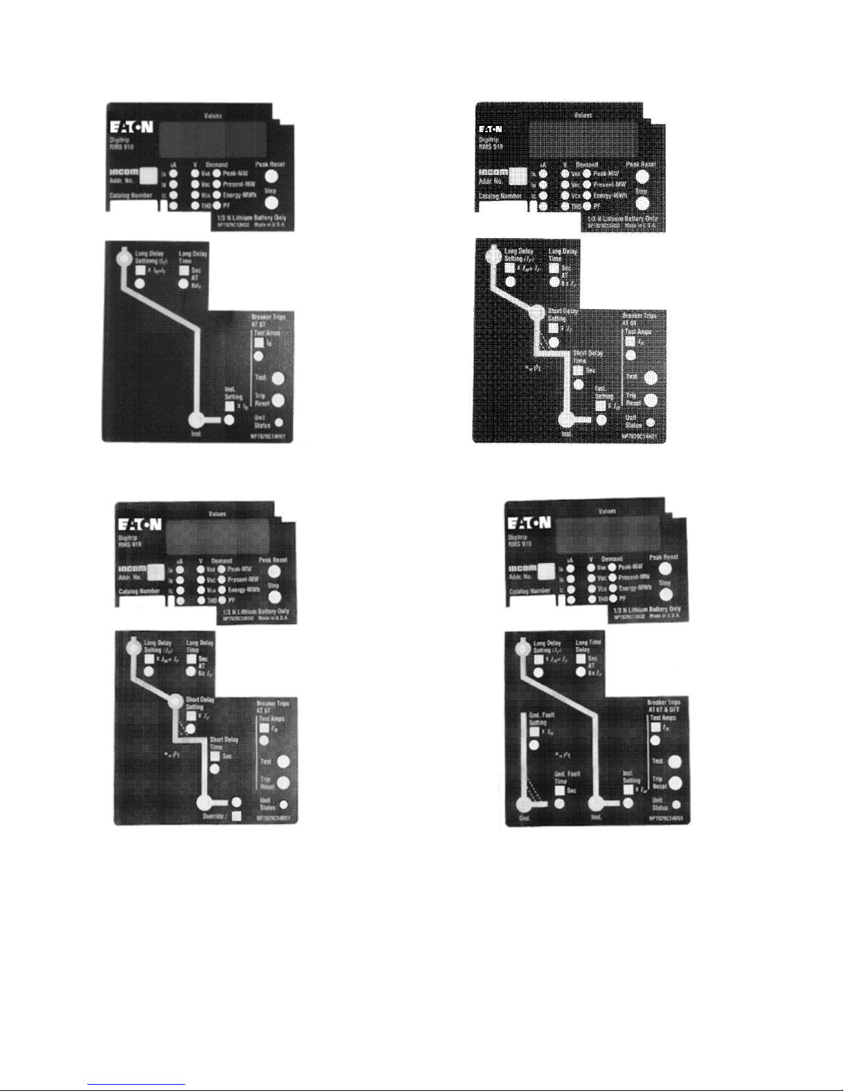
Figure 3. Digitrip RMS 910 Type Ll. . . . . . . . . . . . . . . . . . . . . . . . . . 8
Figure 4. Digitrip RMS 910 Type LS. . . . . . . . . . . . . . . . . . . . . . . . . . 8
Figure 5. Digitrip RMS 910 Type LSI. . . . . . . . . . . . . . . . . . . . . . . . . . 8
Figure 6. Digitrip RMS 910 Type LIG. . . . . . . . . . . . . . . . . . . . . . . . . 8
Figure 7. Digitrip RMS 910 Type LSG. . . . . . . . . . . . . . . . . . . . . . . . . 9
Figure 8. Digitrip RMS 910 Type LSIG. . . . . . . . . . . . . . . . . . . . . . . . 9
Figure 9. Rating Plug. . . . . . . . . . . . . . . . . . . . . . . . . . . . . . . . . . . . .13
Figure 10. Power/Relay Module. . . . . . . . . . . . . . . . . . . . . . . . . . . . .14
Figure 11. Potential Transfer Module. . . . . . . . . . . . . . . . . . . . . . . . . .14
Figure 12. Auxiliary Power Module. . . . . . . . . . . . . . . . . . . . . . . . . . .15
Figure 13. Long Delay Current Settings. . . . . . . . . . . . . . . . . . . . . . .16
Figure 14. Long Delay Time Settings. . . . . . . . . . . . . . . . . . . . . . . . .16
Figure 15. Short Delay Current Settings. . . . . . . . . . . . . . . . . . . . . . .16
Figure 16. Short Delay Time Settings. . . . . . . . . . . . . . . . . . . . . . . . .17
Figure 17. Instantaneous Current Settings. . . . . . . . . . . . . . . . . . . .17
Figure 18. Ground Fault Current Settings. . . . . . . . . . . . . . . . . . . . . .17
Figure 19. Ground Fault Time Delay Settings. . . . . . . . . . . . . . . . . . .18
Figure 20. Integral Test Panel (Lower Right Corner of Trip Unit). . . . .18
Figure 21. INCOM with Remote Master Computer. . . . . . . . . . . . . 22
Figure 22. INCOM Network with AEM / BIM. . . . . . . . . . . . . . . . . 23
Figure 23. INCOM Network with Remote Master Computer and . .
AEM / BIM. . . . . . . . . . . . . . . . . . . . . . . . . . . . . . . . . . . 23
Figure A.1 Typical Zone Interlocking (Ground Fault Protection) . . . . 29
Figure A.2 Typical Zone Interlocking Connections with Two Main
Breakers (M1, M2) and a Tie Breaker (T) (Short Delay
Protection). . . . . . . . . . . . . . . . . . . . . . . . . . . . . . . . . . . . 29
List of Tables
Description Page
Table 1. Digitrip RMS 910 Protection Functions. . . . . . . . . . . . . . . . . 7
Table 2. Digitrip RMS 910 Information Functions. . . . . . . . . . . . . . 11
Table 3. Digitrip RMS 910 Trip Unit Message Codes and
their Meanings. . . . . . . . . . . . . . . . . . . . . . . . . . . . . . . . . . 12
Table 4. Ground Fault Current Settings. . . . . . . . . . . . . . . . . . . . . . 17
Table 5. Digitrip RMS 910 Protection Functions. . . . . . . . . . . . . . . 25
EATON CORPORATION www.eaton.com
3

Instruction Leaflet I. L. 29-889B
Effective June 2011
Instructions for Digitrip RMS 910 Trip Unit
Important Safety Instructions
WARNING
DO NOT ATTEMPT TO INSTALL OR PERFORM MAINTENANCE ON
EQUIPMENT WHILE IT IS ENERGIZED. DEATH OR SEVERE PERSONAL
INJURY CAN RESULT FROM CONTACT WITH ENERGIZED EQUIPMENT.
ALWAYS VERIFY THAT NO VOLTAGE IS PRESENT BEFORE PROCEEDING
WITH THE TASK, AND ALWAYS FOLLOW GENERALLY ACCEPTED
SAFETY PROCEDURES. EATON CORPORATION IS NOT LIABLE FOR THE
MISAPPLICATION OR MISINSTALLATION OF ITS PRODUCTS.
It is strongly urged that the User observe all recommendations,
warnings and cautions relating to the safety of personnel and equipment, as well as all general and local health and safety laws, codes,
and procedures.
The recommendations and information contained herein are based
on experience and judgment, but should not be considered to be
all-inclusive or covering every application or circumstance which
may arise. If you have any questions or need further information
or instructions, please contact your local representative, or the
Customer Support Center for the type of circuit breaker you have.
1 General Description - Digitrip RMS 910
Trip Unit
1.1 Basic Digitrip RMS 910 Trip Unit
The Digitrip RMS 910, illustrated in Figure 1, is a Trip Unit suitable
for use in types DS and DSL Low-Voltage AC power circuit breakers
and type SPB Systems Pow-R circuit breakers and Series C R-Frame
molded case circuit breakers. The Digitrip RMS 910 Trip Unit provides five basic functions:
Function Section
Protection 1.1.2 – 1.1.5 and 3
Information 1.1.1 and 1.2
Monitors 1.2.1
Current 1.2.1.1
Voltage 1.2.1.2
Power, Power Factor and Energy 1.2.1.3
Harmonics and [THD] 1.2.1.4 and 5.7
Testing 4
Communications 1.4 and 5
Remote CLOSE / OPEN Control 5.8
Digitrip RMS 910 provides true RMS current sensing for proper correlation with thermal characteristics of conductors and equipment.
Interchangeable rating plugs are provided to establish the continuous
current rating of each circuit breaker. The Digitrip RMS 910 Trip Unit
is designed for use in industrial circuit breaker environments where
the ambient temperatures can range from -20°C to +85°C (-4°F to
185°F) and rarely exceed 70 to 75°C (158 to 167°F) . If, however,
temperatures in the neighborhood of the Trip Unit do exceed this
range, the Trip Unit performance may be degraded. In order to
insure that the tripping function is not compromised due to an overtemperature condition, the Digitrip RMS 910 microcomputer chip has
a built-in over-temperature protection feature, factory set to trip the
breaker if the chip temperature is excessive. If over-temperature is
the reason for the trip, the Long Delay Time LED will light "RED", and
the word "TEMP" will appear in the display window.
The Trip Unit employs the Eaton custom designed integrated circuit
microprocessor which includes a micro-computer to perform its
numeric and logic functions. The principle of operation is described
by the block diagram shown in Figure 2.
In the Digitrip RMS 910 Trip Unit, all required sensing and tripping
power to operate its protection function is derived from the current
sensors in the circuit breaker. The secondary currents from these
sensors provide the correct input information for the protector functions, as well as tripping power, whenever the circuit breaker is
carrying current. These signals develop analog voltages across the
appropriate sensing resistors including:
4
EATON CORPORATION www.eaton.com
1. Phase currents;
2. Ground current or Neutral current (when supplied);
3. Rating plug; and
4. Phase Voltages.
The resulting analog voltages are digitized by the custom designed
integrated circuits. The micro-computer, in cyclic fashion, repeatedly
scans the voltage values across each sensing resistor and enters
these values into its Random Access Memory (RAM). The data used
to calculate true RMS current values, which are then repeatedly
compared with the protection function settings and other operating data stored in the memory. The software program then determines whether to initiate protection functions, including tripping the
breaker through the low energy trip device (Flux Transfer Shunt Trip
or Direct Trip Actuator) in the circuit breaker.
Instructions for Digitrip RMS 910 Trip Unit
1.1.1 Operational Status and Protection TRIP Indicators
The "Green" Light Emitting Diode (LED) in the lower right corner of
the Trip Unit (Figure 1) "blinks" once each second to indicate the Trip
Unit is operating normally.
ote:N If the LED is steadily "GREEN", i.e. not blinking, the Trip Unit is not
ready. Check the 120 VAC control power to the Power / Relay Module, if the
LED is not blinking (see Section 1.4.).
The LEDs, shown in Figures 1 and 3 thru 8 on the face of the Trip
Unit, light "RED" to indicate the reason for any automatic trip operation. As indicated in Figures 3 - 8, each LED is strategically located
in the related segment of the time-current curve depicted on the
face of the Trip Unit. The reason for trip is identified by the segment
of the time-current curve where the LED is lighted "RED", and is
also identified on the Display. Following an automatic protection trip
operation, the external control power to the Power / Relay Module
(see Section 1.4) will maintain the LED "RED" and will continue to
send a TRIP signal to LOCKOUT the circuit breaker until the Trip
Unit is RESET. The Digitrip RMS 910 Trip Unit can be RESET in two
ways:
•
Either press and release the "TRIP RESET" button (See Figure 1
lower right corner just above the "UNIT STATUS" LED);
or
•
By the "Trip Reset" remote communications function (see Section
5.9.).
Instruction Leaflet I. L. 29-889B
Effective June 2011
Green LED's
Light to Identify
Which Value Is
Presently Being
Displayed in
Window
The Unit INCOM
Address
Catalog Number
LED's light "Red"
to indicate cause
of trip
Time-Current curve for
Phase Protection
Time-Current
Curve for Ground
Protection
SPB Rating Plug
Keyed
Receptacle
for Auxiliary
Power Module
Connector (See
Section 1.6)
4-Character
Display Window
Press and release "PEAK RESET"
Push button to Reset Peak Demand
Reading to Zero
Press and release "STEP" Push button
to Display Value of Next Parameter in
Window
DS Rating Plug
Press and Release "Test"
Push Button to Initiate
Self-Test (See Section 4)
Press and Release "Trip
Reset" Push Button to
Reset Trip Unit
R-Frame Rating Plug
Figure 1. Digitrip RMS 910 Trip Unit Type LSIG with Rating Plug.
View Settings in
Window
Adjust Protection Settings
for Desired Values with
Rotary Switches
Trip Unit Operation Status
"Blinking Green"=OK (See
Section 1.1.1)
EATON CORPORATION www.eaton.com
5
Instruction Leaflet I. L. 29-889B
Effective June 2011
Instructions for Digitrip RMS 910 Trip Unit
Figure 2. RMS Digitrip 910 Trip Unit - Block Diagram.
In the event that control power is lost, the back-up battery in the
Rating Plug (see Section 1.3 and Figures 1 and 9) continues to
supply power to the LEDs. To check the status of the battery, see
Section 4.5.
ote:N The Digitrip RMS 910 performs all of its protection functions regardless
of the status of the battery. The battery ser ves only to maintain the indication
of the reason for automatic trip.
Press and release the "TRIP RESET" push-button shown in Figure 1,
to turn "Off" the LEDs following a trip operation.
1.1.2 General Over-Current Protection
The Digitrip RMS 910 Trip Unit is completely self-contained and
when the circuit breaker is closed, requires no external control
power to operate its protection systems. It operates from current
signal levels and control power derived through current sensors integrally mounted in the circuit breaker.
The Digitrip RMS 910 Trip Unit is available in six different types.
Each Trip Unit may be equipped with a maximum of five phase and
two ground (time-current) settings (see Section 3) to meet specific
application requirements. The protection available for each type is
summarized in Table 1, and illustrated in Figures 3 through 8:
Protection Functions Type Figure
Long Time / Instantaneous LI* 3
Long Time / Short Time LS* 4
Long Time /Short Time /
lnstantaneous
Long Time / Instantaneous
/ Ground
Long Time / Short Time /
Ground
Long Time / Short Time /
lnstantaneous / Ground
ote:N RMS Digitrip Type LI, LS and LSI Trip Units can be applied on 3-pole or
4-pole circuit breakers for protection of the neutral circuit, IF the circuit breaker is wired and MARKED for NEUTRAL PROTECTION. Refer to the National
Electric Code for appropriate application of 4-pole breakers.
LSI* 5
LIG 6
LSG 7
LSlG 8
6
EATON CORPORATION www.eaton.com

Instructions for Digitrip RMS 910 Trip Unit
Instruction Leaflet I. L. 29-889B
Table 1. Digitrip RMS 910 Protection Functions.
Trip Unit Type RMS Digitrip 910
Catalog Number S S S
Suffix Number 91 92 93 94 95 96
Instruction Leaflet No. I.L. 29-889
Long-Time Delay Protection
Adj. Current Setting (Pick-up)
Adj. Time Delay Setting
Long Time Memory
High Load Alarm
ALARM Indication at Trip Unit
Remote ALARM Signal Contacts
Short-Time Delay Protection
Adj. Current Setting (Pick-up)
Adj. Time Delay Setting
Opt. "I Squared T" Curve Shape
Opt. Zone Interlocking
Instantaneous Protection
Adj. Current Setting (Pick-up)
DISCriminator (11 x) IN or OUT
OverRIDE (>short time current rating)
Natural Current Protection n n n 1.1.1
Ground Fault Protection
Adj. Current Setting (Pick-up)
Adj. Time Delay Setting
Opt. "I Squared T" Curve Shape
Opt. Zone Interlocking
Ground Fault Time Memory
Trip Unit Over-Temp TRIP X X X X X X 1.1
Auto Lock-Out after TRIP c,r c,r c,r c,r c,r c,r 1.1.2
LED Indicators on TRIP Unit
Trip Unit Status (OK = blinking)
Long Trip Delay TRIP
Short Time Delay TRIP
INStantaneous TRIP
OverRIDE / DISCriminator TRIP
Ground Fault TRIP
Rating Plug Back up Battery Status X X X X X X 4.5
Integral Test Provision X X X X X X 4
POWER / RELAY MODULE
Output Signal Contacts X X X X X X 1.4
Long-Time Delay TRIP X X X X X X 1.4
Short-Circuit TRIP (includes any of:)
• Short Time Delay Trip
• INStantaneous TRIP
• OverRIDE / DISCriminator TRIP
Ground Fault TRIP X X X 1.4
Natural Current ALARM X X X 1.4
High LoaD ALARM X X X X X X 1.4
LEGEND: x = Function included for this trip unit.
c = 120 Vac Control Power required to maintain Lockout.
n = Circuit Breaker must be equipped for Natural Protection.
r = Trip Unit can be re-set Remotely via INCOM / IMPACC.
* = DISCriminator is also called “Making Current Release”
1 = n/a for Type DS Breakers.
“blank” = Function n/a for this Trip Unit.
9 9 9
1 2 3
3 3 3
L L L
I S S
I
X X X
X X X
X X X
X X X
X X X
X X
X X
X X
X X
X X
X
1 1 1
X X X
X X X
X X
X X
X
X X X X X X 1.4
S S S
9 9 9
4 5 6
3 3 3
L L L
I S S
G G I
G
X X X
X X X
X X X
X X X
X X X
X X
X X
X X
X X
X X
X
1 1 1
X X X
X X X
X X X
X X X
X X X
X X X
X X X
X X
X X
X
X X X
Refer to I.L.
Section
Number
Table 3
Effective June 2011
3.2
3.3
3.3
1.3
3.4
3.5
3.5
1.1.5
3.6
1.1.3
1.1.4
3.8
3.9
3.9
1.1.5
3.9
1.1.2
1.1.2
1.1.2
1.1.2
1.1.2
1.1.2
EATON CORPORATION www.eaton.com
7
Instruction Leaflet I. L. 29-889B
Effective June 2011
Instructions for Digitrip RMS 910 Trip Unit
Figure 3. Digitrip RMS 910 Type Ll.
Figure 4. Digitrip RMS 910 Type LS.
Figure 5. Digitrip RMS 910 Type LSI.
Figure 6. Digitrip RMS 910 Type LIG.
8
EATON CORPORATION www.eaton.com
Instructions for Digitrip RMS 910 Trip Unit
Figure 7. Digitrip RMS 910 Type LSG.
Instruction Leaflet I. L. 29-889B
Effective June 2011
After an over-current trip operation, the following information is
stored in the Trip Unit memory:
•
the cause of trip;
•
the values of currents at time of trip;
•
the time when the trip operation occurred; and
•
the total number of times the Trip Unit has tripped the breaker
electronically, (does not count shunt trip or manual operations).
If the 120 Vac control power remains available to the Power / Relay
Module, this information can be viewed by INCOM
Section 5.6). Therefore, Users may want to use an uninterruptible
power supply for the control power to the power relay module.
1.1.3 Discriminator (High Initial Current Release)
(For Types LS and LSG Trip Units Only)
When the Digitrip RMS 910 Trip Unit is not equipped with an
adjustable instantaneous protection setting, i.e. types LS or LSG, a
DlScriminator circuit (or high initial current release) is provided. The
non-adjustable release is pre-set at eleven (11) times the installed
rating plug current (I
mately ten (10) cycles following the initial current flow through the
). The DlScriminator is enabled for approxi-
n
circuit breaker, provided the load current exceeds approximately 10%
of the circuit breaker frame (or current sensor) rating. Whenever
the load current falls below 10% the discriminator is rearmed. The
release, once rearmed will remain enabled until the load current
passing through the circuit breaker has exceeded the 10% value
for 10 cycles. Whenever the DlScriminator trips the circuit breaker,
the "OVERRIDE / DIS" LED will light "RED", and the Display will read
"DISC".
In the event the breaker is not intended to trip out on a circuit
whose current could initially be higher than 11 x I
make the DlScriminator inactive.
If a circuit breaker would close onto a high short-circuit current,
when the DlScriminator is inactive, type LS or LSG Trip Units will
rely on the short-time delay function before tripping. If the fault
current exceeds the short-time withstand current capability of the
circuit breaker, the OverRlDe protection function will trip the breaker
without delay (see Section 1.1.4). Also, please see Section 1.1.5 for
other exceptions when Zone lnterlocking is employed.
The DlScriminator (high initial current release) can be made inactive
by turning the "OVERRIDE/" setting switch (nearest the bottom edge
of the Trip Unit) from the "DIS" position, to the "[blank]" position (see
Figures 4 and 7).
ote:N This switch has eight (8) positions, and seven (7) of the positions show
"DIS" in the window, ONLY ONE position shows "[blank]".
ote:N When the "OVERRIDE/"window shows "[blank]", the only fast-acting
high short-circuit protection available is the OVERRIDE (Fixed
Instantaneous) (see Section 1.1.4.).
®
/ IMPACC® (See
, it is possible to
n
Figure 8. Digitrip RMS 910 Type LSIG.
NOTICE
AFTER EACH TRIP OPERATION (WHETHER DUE TO OVERCURRENT
PROTECTION OR REMOTE CONTROL) THE AUTOMATIC LOCKOUT-AFTERTRIP FEATURE OF THE DIGITRIP RMS 910 TRIP UNIT MAINTAINS THE
CIRCUIT BREAKER IN A "TRIP-FREE" CONDITION, PROVIDED 120 VAC
CONTROL POWER REMAINS AVAILABLE TO THE POWER / RELAY MODULE.
THE TRIP UNIT MUST BE RESET BEFORE THE CIRCUIT BREAKER CAN BE
CLOSED AGAIN. THE RESET CAN BE ACCOMPLISHED EITHER LOCALLY BY
PRESSING AND RELEASING THE "TRIP RESET' PUSH BUTTON (SEE FIGURE
1),OR REMOTELY BY THE IMPACC SYSTEM (SEE SECTION 5.9).
EATON CORPORATION www.eaton.com
9

Instruction Leaflet I. L. 29-889B
Effective June 2011
Instructions for Digitrip RMS 910 Trip Unit
1.1.4 OVERRIDE (Fixed Instantaneous)
Each Digitrip RMS 910 Trip Unit has a Fixed Instantaneous "Override"
analog trip circuit pre-set to a value no greater than the short-time
withstand current rating of the circuit breaker in which the Trip Unit
is installed. Since the specific values vary for different circuit breaker types and ratings, refer to time-current curves, listed in Section 6,
for the values applicable to your breaker. If the breaker trips due to
high instantaneous current, the "OVERRIDE/" LED will light "RED",
and the display will read "ORID".
1.1.5 Zone Interlocking
Zone Selective lnterlocking (or Zone Interlocking) is available (see
Figure 2) for Digitrip RMS Trip Units having Short Delay and/or
Ground Fault protection. Zone Selective lnterlocking provides the
fastest possible tripping for faults within the breaker's zone of protection, and yet also provides positive coordination among all breakers in the system (mains, ties, feeders and downstream breakers) to
limit the outage to the affected part of the system only. When Zone
lnterlocking is enabled, a fault within the breaker's zone of protection
will cause the Trip Unit to:
•
Trip the affected breaker instantaneously, and
•
Send a signal to upstream RMS Digitrip Trip Units to restrain from
tripping immediately. The restraining signal causes the upstream
breakers to follow their set coordination times, so that only the
minimum service is disrupted, while the fault is cleared in the
shortest time possible.
This signal requires that only a single pair of wires be connected
from the interlock output terminals of the downstream breaker's
Trip Unit, to the interlock input terminals of the upstream breaker's
Trip Unit. For specific instructions see the applicable connection diagrams for your breaker listed in Section 6.
ote:N If a breaker (M) receives a Zone lnterlocking signal from another
breaker (F) that is tripping, but the fault current level is less than the setting
for breaker (M), the presence of the Zone lnterlocking signal from the other
breaker (F) can not cause breaker (M) to trip.
CAUTION
IF ZONE INTERLOCKING IS NOT TO BE USED (I.E.: STANDARD TIMEDELAY COORDINATION ONLY IS INTENDED), THE ZONE INTERLOCKING
TERMINALS MUST BE CONNECTED WITH JUMPER WIRES, AS SPECIFIED
ON THE CONNECTION DIAGRAMS FOR YOUR BREAKER (SEE SECTION
6), SO THE TIME DELAY SETTINGS WILL PROVIDE THE INTENDED
COORDINATION.
For examples of how Zone Selective lnterlocking may be used, See
Appendix A.
1.2 Four Character Information Display Window
The four-digit alpha-numeric display window, illustrated in Figures 1
and 2, serves two basic purposes: instrumentation and mode of trip
and trouble indication. The information displayed in the window is
listed in Tables 2 and 3.
1.2.1 Values Displayed During Normal Service
The alpha-numeric display window provides informational values
under normal service conditions and coded messages after an alarm
condition or after an over-current trip operation. The 12 Green LEDs
below the display window indicate which value of current, voltage,
power, power factor, energy, or Total Harmonic Distortion (THD) is
being displayed. The value in the display window indicates the present value of the parameter whose LED is lighted "Green". In Figure
1, the first four "Green" LEDs identify which current (kA) value is
being displayed, i.e.: phase A current (I
phase C current (I
(neutral) (I
button will step next to the Green LEDs that identify the breaker's
D
), ground current (IG), or current in the fourth pole
C
). The press and release operation of the "Step" push-
phase to phase voltages being displayed; i.e.: (V
Values are in volts RMS.
), phase B current (IB),
A
), (VBC), (VCA).
AB
A repeat press and release of "Step" pushbutton will proceed to the
four Green LEDs that identify Peak Power Demand (MW), Present
Power Demand (MW), Energy Demand (MWh), and Power Factor
(PF). The next press and release of "Step" push-button will show the
(THD) for phase (I
) are illuminated. Repeating "Step" push-button operation will
and (I
A
show (THD) values for (I
release one more time will sequence back from the (THD) of (I
the (kA) current of (I
monic data.
) current. Notice that both the green LEDs (THD)
A
) and (IC) currents. Repeating press and
B
). See Section 1.2.1.4 for displaying per har-
A
C
) to
1.2.1.1 Instrumentation - Current Values
During the normal service conditions, with the circuit breaker closed,
the Digitrip 910 serves as an ammeter, displaying the individual
phase currents (I
(neutral) current (I
or fourth pole protection. Current values are displayed in kA. The
, IB, IC) and ground current (IG) or the fourth pole
A
), provided the circuit breaker is set up for ground
D
value displayed is current in the pole (or ground) indicated by the
"Green" LED that is turned "On". Press and release the (Black)
"STEP" push-button to view the values of current in the other phases
(see Figure 1). The range, accuracy and wave shape parameters for
current values displayed are:
RANGE: 0 to 9.999 kA if I
0 to 99.99 kA if I
ASSUMES: 5% < Current < 100% of Frame Rating for Series
C
®
R-Frame or Type SPB circuit breaker.
≤ 1000 A
n
>1000A
n
or
5% < Current < 100% of [Current] Sensor Rating
for Type DS circuit breaker.
ACCURACY: ± 2% of Frame Rating for Series C
®
R-Frame or
Type SPB circuit breakers.
or
± 2% of [Current] Sensor Rating for Type DS
circuit breaker.
10
EATON CORPORATION www.eaton.com
 Loading...