

Eaton Digitrip RMS, Digitrip OPTIM Instruction Leaflet
Supersedes IL29C713D dated March 2007
Digitrip RMS and Digitrip OPTIM Trip Units Used with
R-Frame Circuit Breakers
TABLE OF CONTENTS PAGE
1.0 Supplementary Information................................... 2
2.0 Digitrip RMS and Digitrip OPTIM Trip Units .......... 2
3.0 Rating Plugs.......................................................... 3
3.0.1 Digitrip RMS Plugs for 510, 610, 810,910............. 3
3.0.2 Digitrip RMS Plug for 310 ..................................... 3
3.0.3 Digitrip RMS Plugs for OPTIM 750, 1050 ............. 3
3.0.4 Rating Plugs – Battery .......................................... 3
3.1 Installation and Removal of Trip Components ..... 4
3.2 Installation of Rating Plug ..................................... 4
3.3 Trip Unit Removal ................................................. 5
3.4 Trip Unit Replacement .......................................... 6
4.0 Digitrip RMS Model Considerations ...................... 6
4.1 Digitrip RMS 310 ................................................... 6
4.2 Digitrip RMS 510 ................................................... 7
4.3 Digitrip RMS 610 ................................................... 7
4.4 Digitrip RMS 810 ................................................... 8
4.5 Digitrip RMS 910 ................................................... 8
4.6 Digitrip OPTIM 750................................................ 8
4.7 Digitrip OPTIM 1050.............................................. 8
4.8 Reset Operation.................................................... 9
5.0 Principle of Operation............................................ 9
5.1 General ................................................................. 9
5.2 Digitrip RMS Trip Assembly ........................... 9
5.3 Flux Shunt Trip.................................................... 11
5.4 Ground Fault Protection ...................................... 12
5.4.1 General ............................................................... 12
5.4.2 Residual Sensing ................................................ 12
5.4.3 Source Ground Sensing...................................... 12
5.4.4 Ground Fault Settings ......................................... 12
5.5 Current Sensors.................................................. 12
5.6 Digitrip RMS Accessories.................................... 13
5.6.1 Power/Relay Module ........................................... 13
5.6.2 Potential Transformer Module............................. 13
5.6.3 Dielectric Testing ................................................ 13
5.7 Connection Diagram ........................................... 13
5.8 Trip Unit Settings Protection ............................... 13
6.0 Testing ................................................................ 14
6.1 Function Field Testing......................................... 14
6.2 Performance Testing for Ground Fault Trip Units 14
6.2.1 Code Requirements ............................................ 14
6.2.2 Standards Requirements .................................... 14
6.2.3 General Test Instructions.................................... 15
7.0 Record Keeping .................................................. 16
8.0 References.......................................................... 16
8.1 R-Frame ....................... ................................ 16
8.2 Digitrip RMS Trip Units........................................
8.3 Time Current Curves........................................... 18
8.4 Miscellaneous .................................................... 18
18
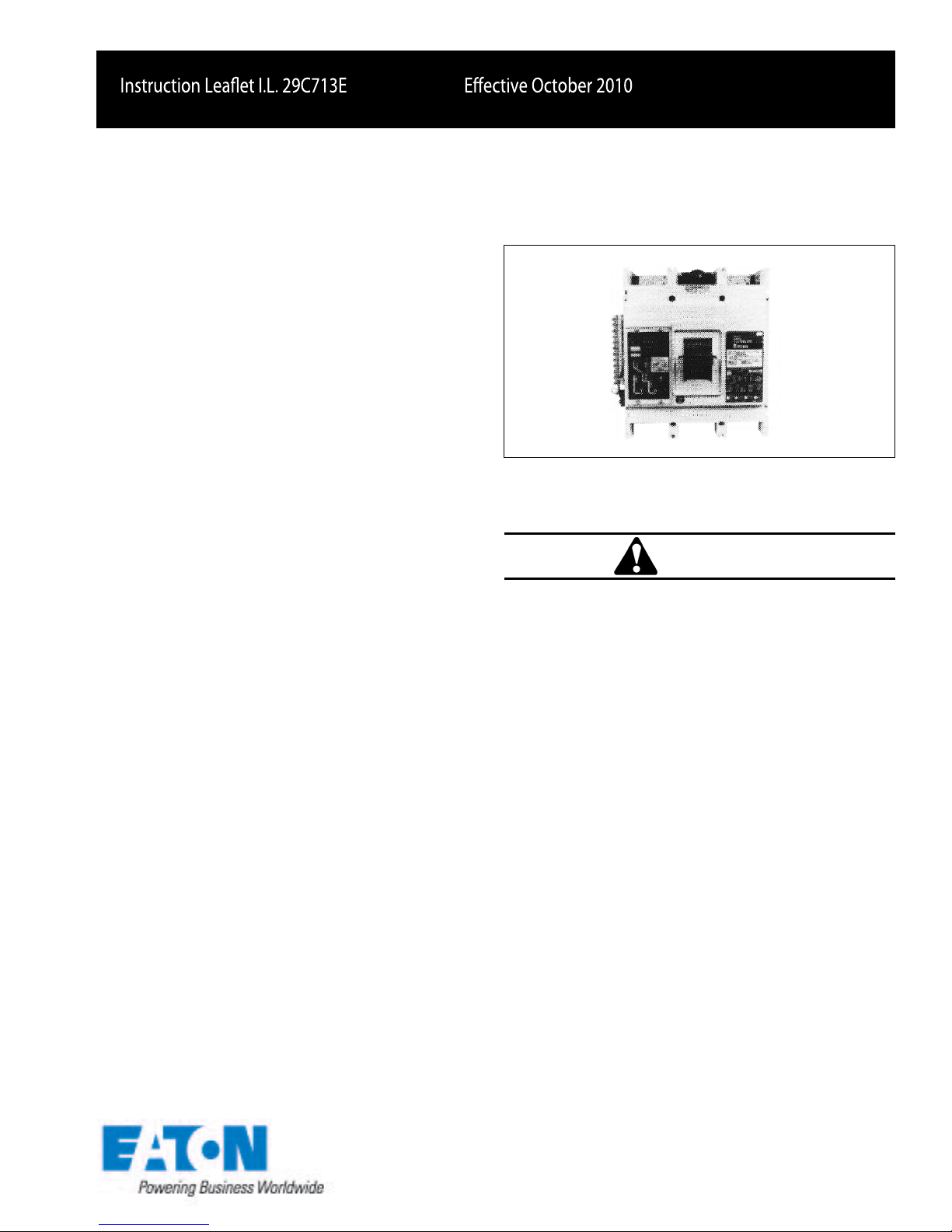
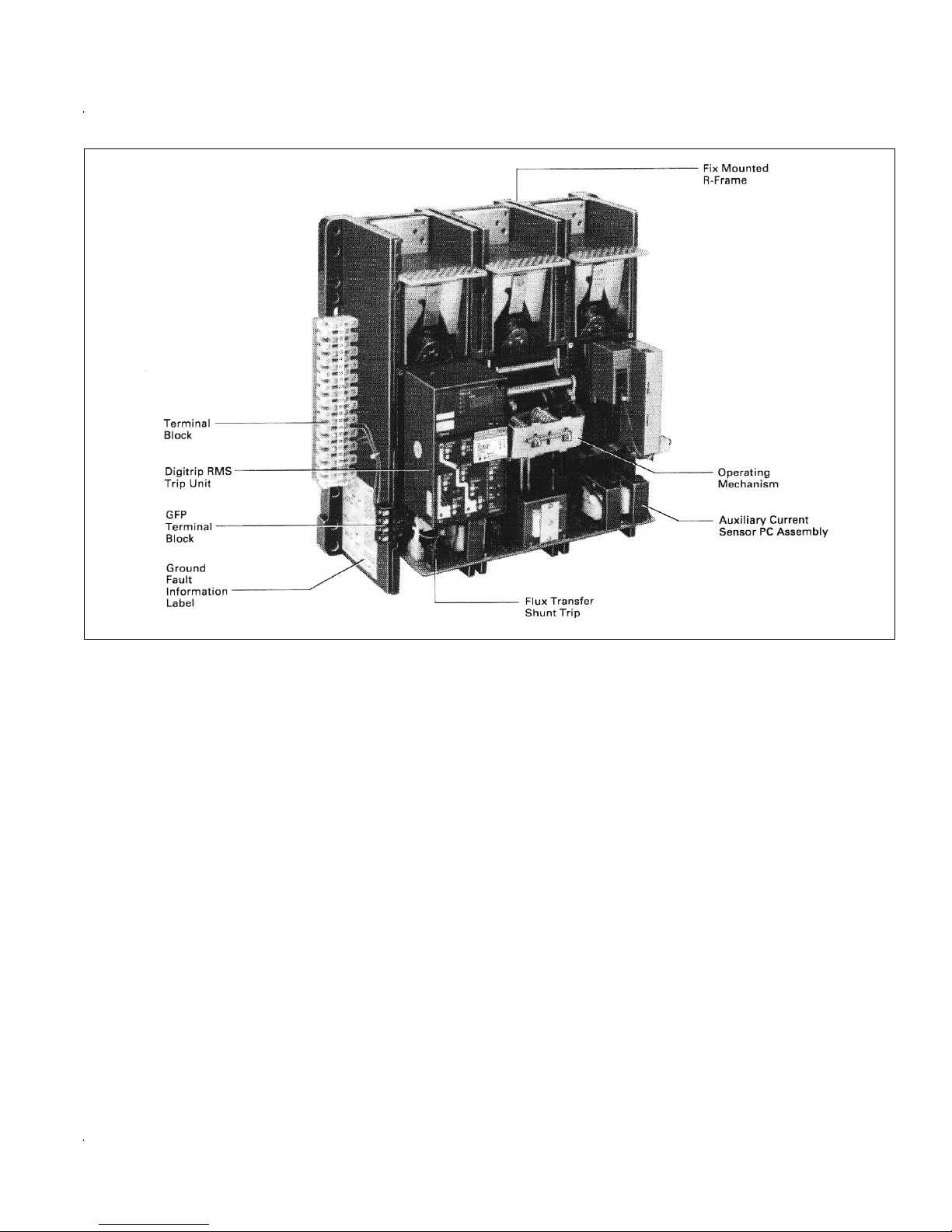
Fig. 1. View of R- Frame Circuit Brea ker
Shown with Digitrip RMS 510 Trip Unit Installed
WARNING
DO NOT ATTEMPT TO INSTALL OR PERFORM MAINTENANCE ON EQUIPMENT WHILE IT IS ENERGIZED.
DEATH, SEVERE PERSONAL INJURY, OR SUBSTANTIAL PROPERTY DAMAGE CAN RESULT FROM CONTACT WITH ENERGIZED EQUIPMENT. ALWAYS
VERIFY THAT NO VOLTAGE IS PRESENT BEFORE
PROCEEDING WITH THE TASK, AND ALWAYS FOLLOW GENERALLY ACCEPTED SAFETY PROCEDURES.
EATON IS NOT LIABLE FOR THE MISAPPLICATION
OR MISINSTALLATION OF ITS PRODUCTS.
The user is cautioned to observe all recommendations,
warnings and cautions relating to the safety of personnel
and equipment, as well as all general and local health
and safety laws, codes , and procedures .
The recommendations and information contained herein
are based on Eaton experience and judgment,
but should not be considered to be all-inclusive or covering every application or circumstance which may arise. If
any questions arise, contact Eaton for further
information or instructions.

Eective Date October 2010 Instruction Leaet 29C713E
Eective October 2010
Fig. 2a View of Five Basic Models of the Digitrip RMS Trip Unit
1.0 SUPPLEMENTARY INFORMATION
The instructions contained in this book supplement the
instructions for R- F rame Circuit Breakers cov
in l.L. 29C107 and Connection Diagram 290714.
2.0 DIGITRIP RMS AND DIGITRIP OPTIM TRIP UNITS
This instruction book specically covers the application of
Digitrip RMS and Digitrip OPTIM Trip Units installed in
R- Frame Circuit Breakers as illustrated in Fig. 1.
Digitrip RMS and Digitrip OPTIM Trip Units are ac
devices that employ microprocessor-based technology
that provides true rms current sensing means for proper
correlation with thermal character
equipment. The
circuit protection. This is achiev
ondary current signals received from the circuit breaker
current sensors and initiating tr
breaker shunt trip when pre-set current levels and time
delay settings are exceeded.
In addition to the basic protection function, Digitrip RMS
Trip Unit models 510, 610, 810, 910 and Digitrip OPTIM
750 and 1050, provide mode of trip information and integral test provisions.
The protection section of the Digitrip Trip Unit can be
equipped with a maximum of ve phase and two ground
(time current) curve shaping adjustments. The exact
primary function of the Digitrip Trip Unit is
istics of conductors and
ed by analyzing the sec-
ip signals to the circuit
ered
Fig. 2b View of the Two Basic Models of the Digitrip
OPTIM Trip Unit
selection of the available protection function adjustments
is optional to satisfy the protection needs of any specic
installation. The short delay and ground fault pick-up
adjustments can be set for either at or I²t response. A
pictorial representation of the applicable time-current
curve for the selected protection functions is provided on
the face of the trip unit for user reference.
On the Digitrip Models 510, 610, 810, 910, 750 and 1050
red LEDs that are imbedded in the Time-Current curves
EATON CORPORATION www.eaton.com Page 2

Eective Date October 2010 Instruction Leaet 29C713E
Eective October 2010
depicted on the face of the trip unit provide mode of trip
indication for ground fault, overload and short circuit trip
operations.
Digitrip RMS Models 510, 610, 810, and 910 that are not
equipped with an adjustable instantaneous trip element
(LS and LSG) are provided with a making current release
which is referred to as a DIScriminator. The DIScriminator is switch selectable to disable this function. In addition, on all models, a high-level instantaneous override
circuit is provided to ensure rapid circuit clearing under
abnormal fault current conditions. The override is set for
16,000A ±15%.
Digitrip RMS Trip Units are available in ve basic models,
as illustrated in Fig. 2a: 310, 510, 610, 810, and 910.
Separate instruction leaets referenced in Section 8.2
cover the basic functions and features of each model.
Digitrip OPTIM Trip Units are available in two models as
illustrated in Fig. 2b: 750 and 1050. A separate related
series of 3 instruction leaets, referenced in Section 8.0,
cover the two trip unit models, the hand held OPTIMizer
and the panel mounted BIM (Breaker Interface Module).
This instruction book is arranged to describe the unique
features of each type as they relate to their application in
R- Frame Circuit Breakers . Table 1 illustrates the
available functions and features of each of the trip unit
models.
3.0 RATING PLUGS
3.0.1 Digitrip RMS Plugs 510, 610, 810, 910
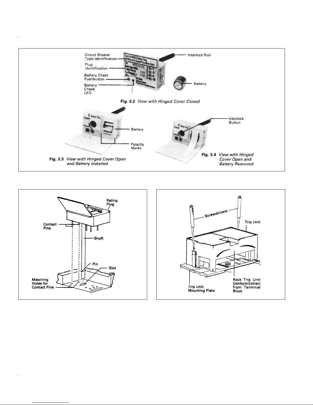
Rating Plugs, as illustrated in Figures 3.2 thru 3.4, determine the maximum continuous current rating of the circuit
breaker. All protection function settings on the face of the
trip unit are expressed in per unit multiples of the plug
ampere rating (I
) . A fractional multiplier of the plug
n
ampere rating is set by the long delay setting switch to
further dene the (l
) continuous current rating for the
r
long time and short time functions. See curve references
in Section 8.3.
Available rating plugs are shown in Table 2b. Plugs must
be selected to match the desired continuous current rating of the circuit breaker as well as the frame rating.
3.0.2 Digitrip RMS 310- Plugs
This family of plugs is illustrated in Fig. 3.1. This plug
design will not mechanically t into the other Digitrip
models. On the model 310 units the continous current
rating (I
) equals the rating plug ampere rating (l ). The
r
n
Fig. 3.1 Typical Rating Plug for Digitrip RMS 310
plug scaled by the short delay pickup or instantaneous
switch settings provides short circuit protection levels.
See curve references in Section 8.3. Available rating
plugs are shown in Table 2a. Plugs must be selected to
match the desired continuous current rating of the circuit
breaker as well as frame rating.
3.0.3 Digitrip RMS Plugs for OPTIM, 750 and 1050
The Digitrip OPTIM rating plugs are similar in construction to the plug family described in Section 3.0.1. The
plugs are marked Digitrip RMS. The plug determines the
maximum continuous current rating of the circuit breaker.
The pickup settings are ultimally loaded via software into
the trip unit in per unit but are displayed for user's ease as
an ampere value. The Long Delay Current Setting (Long
Delay Pickup) loaded in amperes via an external device
is actually a fractional multiplier of the plug ampere rating
(I
) and in turn denes a (l ) continuous current rating for
n
the long time and short time functions. See curve refer-
r
ences in Section 8.3. Available rating plugs are shown in
Table 2c. Plugs must be selected to match the desired
continuous current rating of the circuit breaker as well as
frame rating.
3.0.4 Rating Plugs Battery
For all models except Digitrip 310, rating plugs are
equipped with a back-up battery to maintain the mode of
trip operation following a circuit breaker tripping operation
when external control power is not available. The battery
is a long-life lithium type, that is replaceable from the front
of the trip unit, when required, without removing the rating plug. See Figs. 3.2 thru 3.4. Replacement types and
instructions are provided in the Digitrip RMS Trip Unit
instruction leaet referred to in Section 8.2 of this book.
Following a trip operation and with no supplementary
control power available, the battery will maintain the
mode of trip LED for approximately 60 hours.
EATON CORPORATION www.eaton.com Page 3
Eective Date October 2010 Instruction Leaet 29C713E
Eective October 2010
Fig. 3.2 thru 3.4 Typical Rating Plug for Digitrip RMS 510, 610, 810, 910 and Digitrip OPTIM 750, 1050
Fig. 3.5. Installation of Rating Plug
Note: The rating plug must be securely tightened in
the trip unit before operating the circuit breaker.
3.1 Installation and Removal of Trip Components
R- F rame circuit breakers are shipped with the
trip unit installed. Make sure that the trip unit and the circuit breaker are suitable for the intended installation by
comparing nameplate data with any existing equipment
Fig. 3.6. Removal of Trip Unit
and system requirements. If both trip unit and circuit
breaker are suitable, the circuit breaker requires only the
installation of a rating plug to make it operational.
3.2 Installation of Rating Plug
Note: The rating plug mechanically interlocks with
the circuit breaker frame. If the rating plug is not cor-
EATON CORPORATION www.eaton.com Page 4
rectly installed, the circuit breaker cannot be reset or
placed in the ON position.
WARNING
Before the rating plug can be installed, the transparent trip unit cover must be removed from the circuit breaker.
To install the rating plug on Digitrip RMS Models 510,
interlock button to point towards the REMOVE position.
a. Remove transparent trip unit cover after loosening
the four thumbscrews.
b. Make sure arrow on rating plug interlock button is
pointing at REMOVE. Adjust, if necessary, using a
c. Position the rating plug over the trip unit as shown
in Fig. 3.5. The pin on the rating plug shaft must
line up with the matching slot in the trip unit.
d. Push the rating plug in as far as it will go. The
electrical contact pins will enter matching holes in
the trip unit. A springiness will be felt when the rating plug bottoms in the trip unit.
lock button. Press in approximately 1/16-inch and
turn button 90° clockwise to the “ENGAGED” position.
BEFORE YOU FIT THE RATING PLUG INTO THE
TRIP UNIT, BE SURE TO CHECK THAT THE
BREAKER TYPE AND FRAME RATING (OR
SENSOR RATING IF APPLICABLE), MATCH
THOSE PRINTED ON THE RATING PLUG COVER.
INSTALLING A RATING PLUG THAT DOES NOT
MATCH THE BRAKER TYPE AND FRAME
RATING (OR SENSORRATING, IF APPLICABLE),
CAN PRODUCE SERIOUS MISCOORDINATION
AND/OR FAILURE OF THE PROTECTION
SYSTEM.
3.3 Trip Unit Removal
Use the following instructions to remove a Digitrip trip unit
from a circuit breaker.
WARNING
THE VOLTAGES IN ENERGIZED EQUIPMENT CAN
CAUSE DEATH OR SEVERE PERSONAL INJURY.
BEFORE REMOVING THE COVER OF AN R-FRAME
CIRCUIT BREAKER MOUNTED IN AN ELECTRICAL
SYSTEM, MAKE SURE THERE IS NO VOLTAGE AT
LINE OR LOAD TERMINALS. SPECIAL ATTENTION
SHOULD BE PAID TO REVERSE FEED APPLICATIONS TO ENSURE NO VOLTAGE IS PRESENT.
Note: If unit is a Digitrip RMS 310, and an adjustable
rating plug is installed, set rating plug switch marked
a. Press the Push-to-Trip button in the circuit breaker
cover to trip the circuit breaker.
A, B, C, D to the current rating desired.
b. Remove eight cover screws and circuit breaker
f. After adjusting trip unit settings to the desired set-
cover.
tings, close the rating plug's hinged cover and re-
install trip unit transparent cover. Secure in position
with four thumbscrews
.
c. Remove the rating plug. Flip the hinged cover
open. Turn the interlock button counter clockwise to
the REMOVE position. Rating plug will raise
g. Circuit break
the ON and OFF positions.
er can now be reset and switched to
slightly. Grasp rating plug and pull out gently. Make
sure pin in shaft lines up with slot in trip unit. Adjust
position of interlock button as required to ensure a
smooth withdrawal of the shaft.
screwdrivers, lift up on the spring clips located at
each end of the trip unit (see Fig. 3.5).
EATON CORPORATION www.eaton.com Page 5
e. With the screwdrivers in position, gently rock the
trip unit from side to side until it works free from the
circuit breaker.
3.4 Trip Unit Replacement
Make sure the trip unit to be installed is suitable for the
intended installation by comparing the trip unit catalog
number with the nameplate on the circuit breaker frame
located to the right of the handle. Rejection pins are used
in the circuit breaker frame to prevent the installation of
an incorrect trip unit.
a. Remove any existing trip unit by following the
procedures in paragraphs 3.3.a through e.
Note: The replacement trip unit should be installed
before the circuit breaker cover is re-installed.
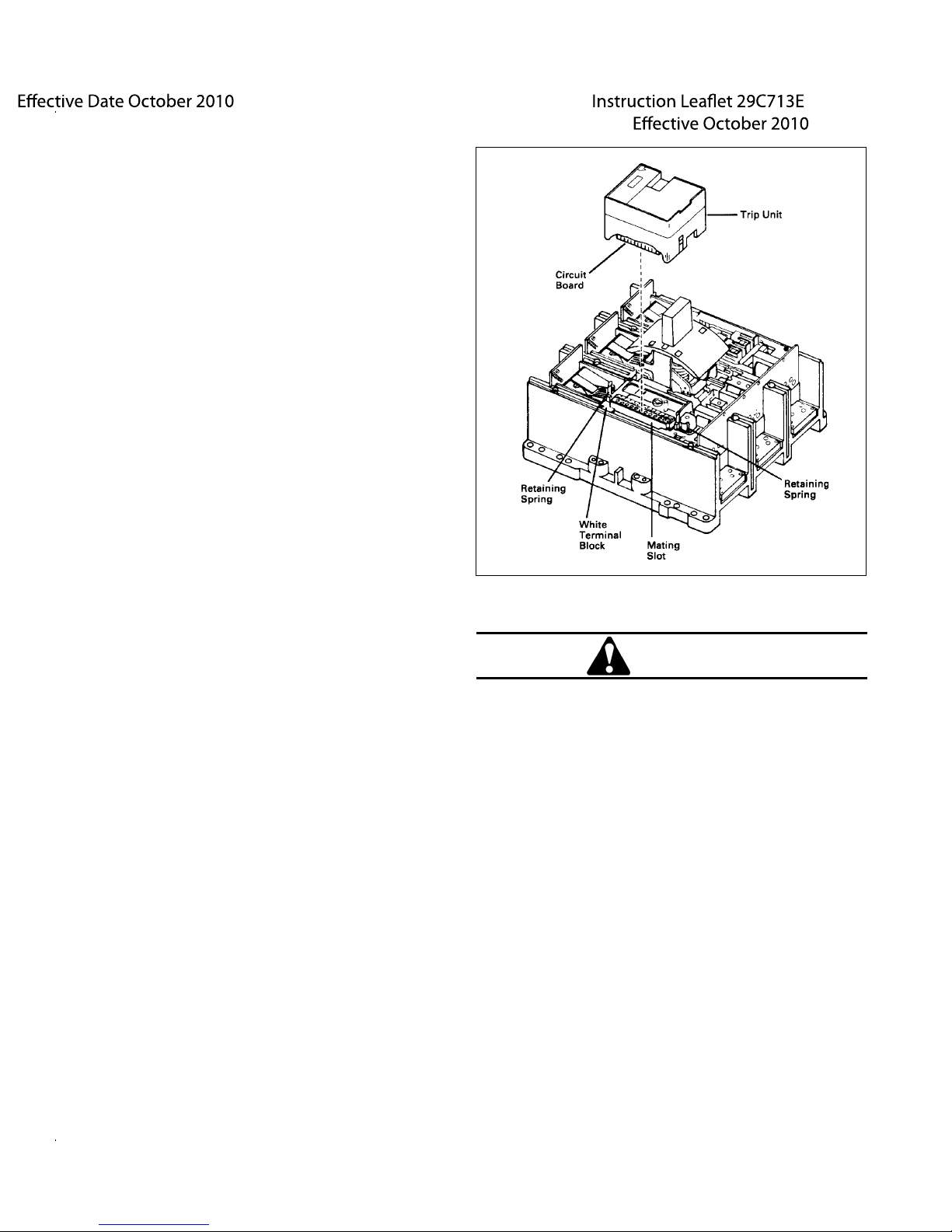
b. Position the replacement trip unit above the white
terminal block to the left of the circuit breaker handle. Align the protruding circuit board with the mating slot in the white terminal block (see Fig. 3.7).
c. Carefully press the trip unit into place. A sharp click
will be heard as the retaining springs click into position.
Fig. 3.7. Installation of Trip Unit
d. Install rating plug (see paragraphs 3.2.b through e).
e. Reinstall the circuit breaker c over. Torque cover
screws to 24 in-lbs.
4.0 DIGITRIP RMS MODEL CONSIDERATIONS
4.1 Digitrip RMS 310
The Digitrip RMS 310 Tr
RMS 310 Trip Unit as described in I.L. 29C883, 3 or 4
auxiliary current transformers and a stab-in trip unit terminal block as shown in Figs. 4 and 5.
The fourth auxiliary current transformer is supplied when
the optional ground fault or neutral protection function is
selected in the trip unit. Also, a side mounted 4-point terminal block is provided to pre-wire the mode of ground
fault sensing used, i.e., residual or source ground. These
connections are shown in Fig. 16.
ip Assembly consists of a Digitrip
CAUTION
IN A DRAWOUT MOUNTED BREAKER TESTING OF A
CIRCUIT BREAKER BY INITIATING A TRIP OPERATION
WHILE IN THE CELL " CONNECTED" POSITION BY
THE EXTERNAL TEST KIT OR THE INTEGRAL TEST
PROVISIONS IN THE DIGITRIP RMS TRIP UNIT IS
NOT RECOMMENDED.
THE TRIPPING OPERATION OF THE CIRCUIT
BREAKER WILL CAUSE DISRUPTION OF SERVICE
AND POSSIBLY PERSONAL INJURY RESULTING
FROM UNNECESSARY SWITCHING OF CONNECTED EQUIPMENT.
TESTING OF A CIRCUIT BREAKER SHOULD BE
DONE ONLY IN THE " TEST", " DISCONNECTED" OR
“ WITHDRAWN" CELL POSITIONS.
WHERE A CIRCUIT BREAKER TRIP OPERATION IS
DESIRED FOR A FIXED MOUNTED CIRCUIT
BREAKER, TESTING SHOULD BE CONDUCTED
ONLY WHEN THE EQUIPMENT IN WHICH THE
BREAKER IS MOUNTED IS COMPLETELY DE-ENERGIZED.
EATON CORPORATION www.eaton.com Page 6
Eective Date October 2010 Instruction Leaet 29C713E
Eective October 2010
Fig. 4. View of 1600A, Type R-Frame Circuit Breaker with Front Cover Removed to Expose Digitrip RMS Trip Unit
4.2 Digitrip RMS 510
The Digitrip RMS 510 Trip Assembly consists of a Digitrip
RMS 510 Trip Unit as described in I.L. 29-885, 3 or 4 auxiliary current transformers and a stab-in trip unit terminal
block as shown in Figs. 4 and 5.
4.3 Digitrip RMS 610
The Digitrip RMS 610 Trip Assembly consists of a Digitrip
RMS 610 Tr
ip Unit
as described in l.L. 29-886, 3 or 4 aux-
iliary current transformers, a stab-in trip unit terminal
lock and a Power/Rela
b
y module mounted as illustrated
in Figs. 4 and 5. The Digitrip RMS 610 Trip Unit is similar
The fourth auxiliary current transformer is supplied when
the optional ground fault protection function is selected in
the trip unit. Also, a side mounted 4-point terminal block
is provided to pre-wire the mode of ground fault sensing
used, i.e., residual or source ground.
to a Digitrip RMS 510 Trip Unit with the addition of a fourdigit display, three-phase (l
rent (I
) or one neutral current ( I ) green pointer LEDs
G
along with a stepping push button as illustrated in
, I
, IC) and one ground cur-
B
A
D
Table 1. Signal contacts are provided for hard wiring
three remote mode of trip indicators (long delay, short cir-
The trip unit contains a receptacle for use with an
cuit, ground fault) and a High-Load remote alarm.
optional Auxiliary Power module (Cat. No. PRTAAPM).
When this module is plugged in the trip unit and connected to a 120V, 50/60 Hz supply, the circuit breaker can
be bench tested using the integral test panel. With the cir-
The ground current pointer LED and ground fault mode of
trip signal contact are supplied only when the ground
fault protection function is provided in the trip unit.
cuit breaker in the closed position, it can be "tripped”
when the test selector switch is in either the "6T ” or “GFT ”
positions.
A 120V, 50/60 Hz 6 VA Power/Relay module is standard
for operating the display and internally mounted signal
relays. The relay contacts are each rated 120V, 1.0A. A
230V 50/60 Hz 6 VA power relay module is also available.
EATON CORPORATION www.eaton.com Page 7

Eective Date October 2010 Instruction Leaet 29C713E
Eective October 2010
The Power/Relay module will maintain the cause of trip
LEDs history and trip history as long as the control power
supply is available. With loss of the control power supply,
only the cause of trip LEDs will be maintained by the
back-up battery located in the rating plug.
The High-Load message and remote alarm switch are
pre-set at 85% of the value of the long delay setting. The
High-Load relay operates and the LED turns "ON” when
the 85% level is exceeded only after an approximate 40
second delay to ride through momentary High-Load conditions.
4.4 Digitrip RMS 810
The Digitrip RMS 810 Trip Assembly is
similar to
the Digitrip RMS 610 Trip Assembly with the addition of a fourdigit display, three-phase (I , I
rent (l
) or one neutral current (l ), green pointer LEDs
G
, IC) and one ground cur-
A
B
D
along with a stepping push button, peak demand, present
demand and energy consumed green pointer LEDs along
with a peak demand reset push button as illustrated in
Table 1. The Digitrip RMS 810 Trip Unit is described in
l.L. 29-888.
The Trip Assembly provides for both local displays on the
face of the trip unit and remote communications via an
IMPACC communication network signal link as illustrated
in Table 1.
4.5 Digitrip RMS 910
The Digitrip RMS 910 Trip Assembly is similar to the Digitrip RMS 810. It is a communicating trip unit that provides all the functions described in Section 4.4 plus the
addition of the following features both locally displayed
and remotely communicated:
1. Phase-to-phase voltages - V ,
AB
, V
V
BC
CA
2. System power factor - PF
, I
3. Total harmonic distortion THD for I
, I
B
C
A
The THD calculation also includes the individual harmonic currents up to the 27 harmonic as a percentage of
the fundamental. Also included with the THD is provisions for waveform capture information via a host computer. Detailed information is provided in l.L. 29-889.
4.6 Digitrip OPTIM 750
The Digitrip OPTIM 750 is a programmable communicating microprocessor-based RMS current sensing trip unit.
For the R-Frame breaker it is physically the same plug-in
trip unit as all the other Digitrip models. There are two
style oerings – Phase Protection with Ground Fault Trip
(Cat. P76LSIG) and Phase Protection with Ground Fault
Alarm (Cat. P77LSIA).
In addition, if desired, an Assemblies Electronic Monitor
(AEM) as described in l.L. 17-216, may also be installed
to show the parameters in Table 1 covered under Note 2.
A communicating panel mounted device, the Breaker
Interface Module (BIM), as described in l.L. 29C893 can
be used to display metering and other transmittable data.
Interconnections for the IMPACC circuit must be connected as shown in l.L. 29-888 and wiring diagram using
twisted pair (shielded) No. 18 AWG conductors.
The three-digit IMPACC address must be set on each trip
unit per instructions given in l.L. 29-888. To insure that
each circuit breaker in an assembly is properly located
after the address is set, the breaker should be identied
with its proper cell location and that reference along with
the breaker IMPACC address marked on the face of the
trip unit in the spaces provided.
In addition to the communication of the breaker data, the
IMPA
CC module allows for remote tripping (via the ux
shunt trip) and closing of the circuit breaker.
The front panel of the unit has 3 or 4 causes of trip LEDs
and a telephone type receptacle for purposes of programming settings, testing and displaying phase currents
via a separate hand-held unit called the OPTIMizer.
There are up to 10 trip functions that can be programmed
which includes both a 1
2
t and 14t curve for the Long-Time
slope. There are also typically ten times the number of
setpoints compared to a front adjustable trip unit. All
transmittable data as well as programming of the trip
curve settings can also be communicated over a twisted
pair cable via the breaker's secondaries (terminals C11,
C12) to either a host computer or a panel mounted
Breaker Interface Module (BIM).
The breaker includes a Power/Relay module per Fig. 5 to
provide power for the communications function and delay
output for alarming.
Detail information on Digitrip OPTIM tr
ip units is in
l.L. 29C891.
4.7 Digitrip OPTIM 1050
The Digitr
ip OPTIM 1050 is a programmable communicating microprocessor-based RMS current sensing trip
unit. For the R-Frame breaker it is physically the same
EATON CORPORATION www.eaton.com Page 8
 Loading...