

Eaton Digitrip 520V, Digitrip 520MCV Instructions Manual

I.L. 66A7534H04
Instructions for Digitrip Models 520V and 520MCV
for use only in Cutler-Hammer T ype VCP-T, VCP-TR
and T -V AC, T-VACR Circuit Breakers
Table of Contents
I.L. 66A7534H04
Page 1
1.0 General Description of Digitrip Trip Units ................. 2
1.1 Protection ............................................................... 3
1.2 Mode of Trip and S tatus Information ........................ 3
1.3 Installation and Removal.......................................... 3
1.3.1 Installation of the Trip Unit............................ 3
1.3.2 Installation of the Rating Plug....................... 3
1.3.3 Trip Unit/Rating Plug Removal...................... 4
1.4 Installing the CH T ype-V Curent Sensors................. 5
1.4.1 Installation of the Rating Plug...................... 5
1.4.2 CH T ype-V Current Sensor Functiionality .... 5
1.5 Plexiglass Cover ..................................................... 5
1.6 Ground Alarm/Power Supply Module (520MCV)....... 5
1.6.1 Auxilary Power............................................ 7
1.6.2 Ground Alarm .............................................. 7
1.6.3 Ground Fault Trip ........................................ 7
1.6.4 Ground Fault Alarm..................................... 7
1.7 Display Feature (520MCV) ...................................... 7
1.8 UL, CSA and CE Recognition.................................. 8
2.0 General Description of VCP-T , VCP-TR
and T-V AC, T -VACR Circuit Breakers.......................8
2.1 General ...................................................................8
2.2 Low Energy Trip Actuator ........................................ 9
2.3 Ground Fault Protection .......................................... 9
2.3.1 General ........................................................ 9
2.3.2 Zero Sequence Sensing ............................... 9
2.3.3 Residual Sensing......................................... 9
2.3.4 Ground Fault Settings................................ 10
3.0 Principles of Operation .......................................... 12
3.1 General ................................................................. 12
3.2 Trip and Operation Indicators................................. 12
3.3 Zone Interlocking ............................................. 12, 28
4.0 Protection Settings ............................................... 14
4.1 General ................................................................. 14
4.2 Long Delay Current Setting ................................... 14
4.3 Long Delay Time Setting ....................................... 14
4.4 Short Delay Current Setting................................... 15
4.5 Short Delay Time Setting ...................................... 15
4.6 Instantaneous Current Setting ............................... 15
4.7 Ground Fault Current Setting................................. 16
4.8 Ground Fault Time Delay Setting .......................... 16
4.9 INCOM (520MCV).................................................. 16
4.9.1 Breaker Interface Module (BIM) .................. 16
4.9.2 Remote Master Computer .......................... 16
4.9.3 INCOM Network Interconnections .............. 17
5.0 Test Procedures.................................................... 18
5.1 Test Precautions ................................................... 18
5.2 When to Test ........................................................ 18
5.3 Functional Field Testing ........................................ 18
5.3.1 Field Test Kit............................................... 18
5.3.2 Handheld Functional Test Kit...................... 19
5.3.2.1 Description of Handheld Test Kit...... 19
5.3.2.2 Test Procedure................................ 19
5.3.2.3 Currents .......................................... 19
5.3.2.4 Batteries ......................................... 19
5.4 Performance T esting of Digitrip Trip Units .............. 19
5.4.1 General ...................................................... 19
5.4.2 Testing using MS-2 MultiAMP® Tester....... 19
5.4.2.1 Description of MS-2 T ester .............. 19
5.4.2.2 Primary Injection Testing ................. 20
5.4.2.3 Secondary Injection Testing............. 21
6.0 Battery................................................................. 23
6.1 General ................................................................. 23
6.2 Battery Check....................................................... 23
6.3 Battery Installation and Removal ........................... 23
7.0 Frame Ratings
(Sensor Ratings and Rating Plugs)....................... 24
8.0 Record Keeping .................................................... 24
9.0 References ............................................................ 24
9.1 Medium V oltage T ype VCP Circuit Breakers.......... 2 4
9.2 Time-Current Curves .............................................. 24
Appendix A Zone Interlocking Examples..................... 28
Appendix B Troubleshooting Guide ............................ 30
Appendix C T ypical Breaker Master
Connection Diagram................................ 32
Appendix D MODBUS Translator Wiring .................... 33
Manufacturer’s Statement ............................................. 34
Effective 8/2006
Page 2
WARNING
DO NOT A TTEMPT TO INST ALL OR PERFORM
MAINTENANCE ON EQUIPMENT WHILE IT IS
ENERGIZED. DEA TH OR SEVERE PERSONAL INJURY
CAN RESUL T FROM CONTACT WITH ENERGIZED
EQUIPMENT . AL W A YS VERIFY THA T NO VOL T AGE IS
PRESENT BEFORE PROCEEDING . AL W A YS FOLLOW
SAFETY PROCEDURES. CUTLER-HAMMER IS NOT
LIABLE FOR THE MISAPPLICA TION OR
MISINST ALLA TION OF ITS PRODUCTS.
WARNING
OBSERVE ALL RECOMMENDA TIONS, NOTES, CAUTIONS, AND W ARNINGS RELA TING TO THE SAFETY
OF PERSONNEL AND EQUIPMENT. OBSERVE AND
COMPL Y WITH ALL GENERAL AND LOCAL HEAL TH
AND SAFETY LAWS, CODES, AND PROCEDURES.
I.L. 66A7534H04
NOTE: The recommendations and information contained
herein are based on experience and judgement, but should
not be considered to be all inclusive or to cover every
application or circumstance which may arise.
NOTE: If you have any questions or need additional
information or instructions concerning the operation or
installation of this device, please contact your local
representative or the Cutler Hammer Customer Support
Center.
1.0 GENERAL DESCRIPTION OF DIGITRIP TRIP UNITS
The Digitrip Trip Unit is a breaker subsystem that provides
the protective functions for a circuit breaker. The trip unit s
are in removable housings, installed in the circuit breaker,
and can be replaced or upgraded in the field by the
customer.
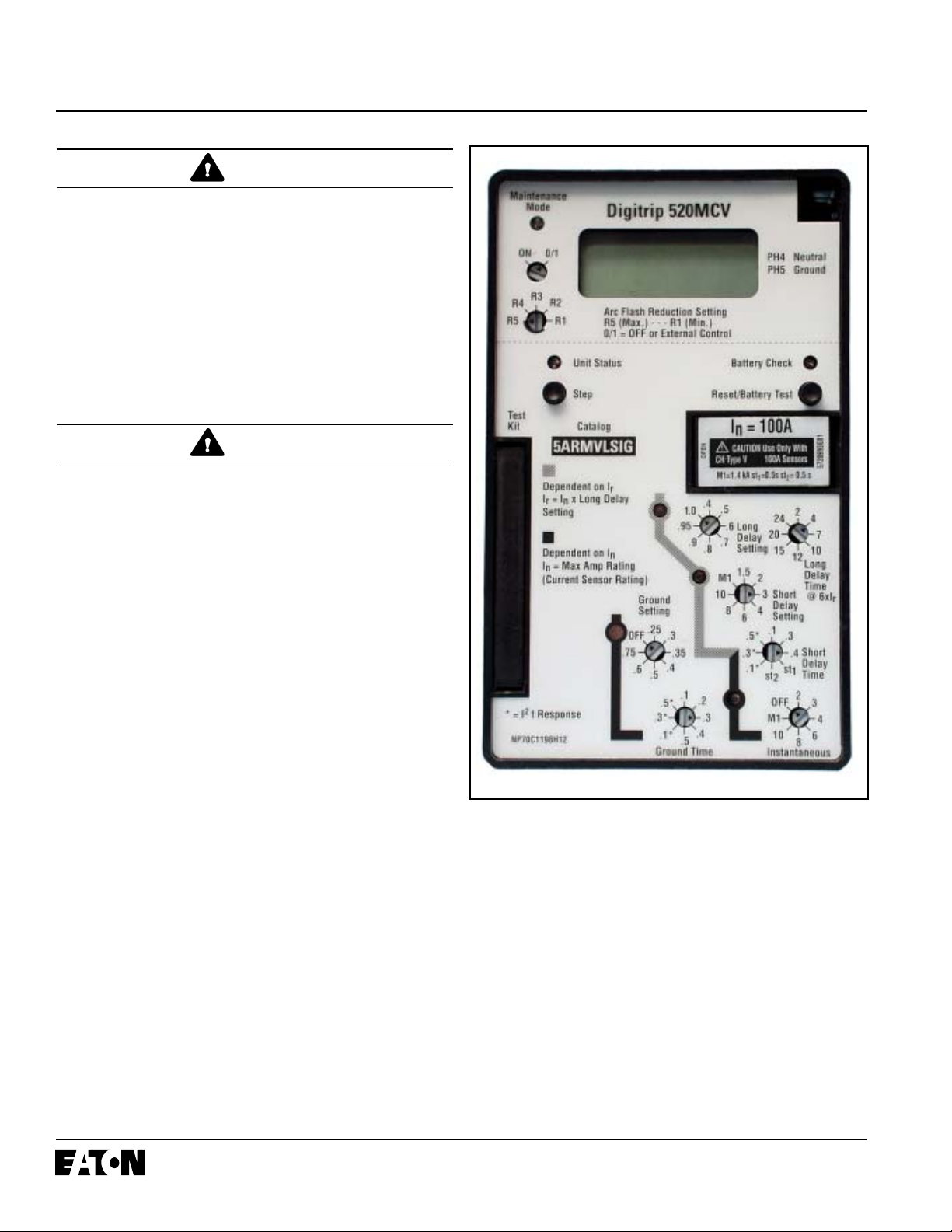
This instruction book specifically covers the application of
the Digitrip Trip Unit s (See Figure 1.1) installed in T ype
VCP-T , VCP-TR, T -V AC or T -V ACR Medium V oltage
Circuit Breakers.
Figure 1.1 Digitrip T rip Unit with Rating Plug
The Digitrip 520V and 520MCV trip units may be applied
on both 50 and 60 Hertz systems. It detects the power and
frequency and adjusts itself automatically .
The Digitrip 520V and 520MCV are self powered and self
protecting trip units designed to function only with the
associated CH T ype-V current sensors.
Effective 8/2006

I.L. 66A7534H04
Page 3
CAUTION
CONNECTING THIS TRIP UNIT TO CURRENT SENSORS OTHER THAN CH TYPE-V MIGHT DAMAGE OR
DESTROY IT .
All trip unit models are microprocessor-based AC protection devices that provide true RMS current sensing for the
proper coordination with the thermal characteristics of
conductors and equipment. The primary function of this
Digitrip trip unit is circuit protection. The Digitrip analyzes
the secondary current signals from the CH T ype-V current
sensors and, when preset current levels and time delay
settings are exceeded, will send an initiating trip signal to
the Trip Actuator of the circuit breaker, causing it to “open.”
In addition to the basic protection function, the Digitrip
520V and 520MCV provide modes of trip indication such
as:
• Long Time trip (overload)
• Short Time trip
• Instantaneous trip
• Ground (Earth) Fault trip
The CH T ype-V current sensors provide the power to the
trip unit. As current begins to flow through the breaker , the
sensors generate a secondary current which powers the
trip unit. No auxilary power is needed to trip the circuit
breaker.
The Digitrip 520V and 520MCV trip units have five phase
and two ground (time-current) curve shaping adjustments.
T o satisfy the protection needs of any specific inst allation,
the exact selection of the available protection function
adjustments is necessary . The short delay and ground
fault pick-up adjustments can be set for either FLA T or I2t
response. A pictorial representation of the applicable timecurrent curves for the selected protection functions is
provided, for user reference, on the face of the trip unit as
shown in Figure 1.1. The user chooses the settings
according to the needs of his application. (See Sections
4.0 & 9.2)
Status LED will also blink at a faster rate if the Digitrip is
in a “Long Pick-up” (overload) mode.
Four red LEDs on the face of the trip units flash to indicate
the cause of trip for an automatic trip operation... i.e.:
Long Delay (overload), Short Delay, Inst antaneous or
Ground (Earth) Fault. A battery , inside the rating plug
compartment of the Digitrip unit, maintains the trip indication until the Reset/Battery T est button is pushed. The
battery is satisfactory if its Battery Check LED lights
green when the Battery Check button is pushed (See
Section 6).
NOTE: The Digitrip unit provides all protection functions
independant of the status of the battery . The battery is
used only to maintain the automatic trip indication.
1.3 Installation and Removal
1.3.1 Installation of the Trip Unit
Align the Digitrip unit with the guide pins and spring clip of
the circuit breaker. Press the unit into the breaker until the
pins on the trip unit seat firmly into the connector housing
and the unit clicks into place (see Figure 1.2).
1.3.2 Installation of the Rating Plug
Insert the rating plug into the cavity on the right-hand side
of the trip unit. Carefully align the three pins on the plug
with the sockets in the cavity . The plug should fit with a
slight insertion force.
WARNING
DO NOT CLOSE THE CIRCUIT BREAKER WHEN THE
DIGITRIP IS REMOVED OR DISCONNECTED. DAMAGE
TO ASSOCIA TED CURRENT TRANSFORMERS MA Y
OCCUR DUE TO AN OPEN CIRCUIT CONDITION.
THERE IS NO PROTECTION FOR THE LOAD CIRCUIT .
1.1 Protection
The Digitrip trip system; including associated CH T ype-V
current sensors, require no external control power to
operate their protection systems. They operate from
current signal levels derived through the CH Type-V current
sensors.
1.2 Mode of Trip and S tatus Information
A green light emitting diode (LED), labeled Unit Status in
Figure 1.1, blinks approximately once each second to
indicate that the trip unit is operating normally . This Unit
Effective 8/2006
CAUTION
IF A RATING PLUG IS NOT INST ALLED IN THE TRIP
UNIT, THE UNIT WILL INITIATE A TRIP WHEN IT IS
ENERGIZED. IN ADDITION THE INST ANT ANEOUS LED
OF THE DIGITRIP TRIP UNIT WILL LIGHT DUE TO A
MISSING OR BAD RA TING PLUG .
Page 4
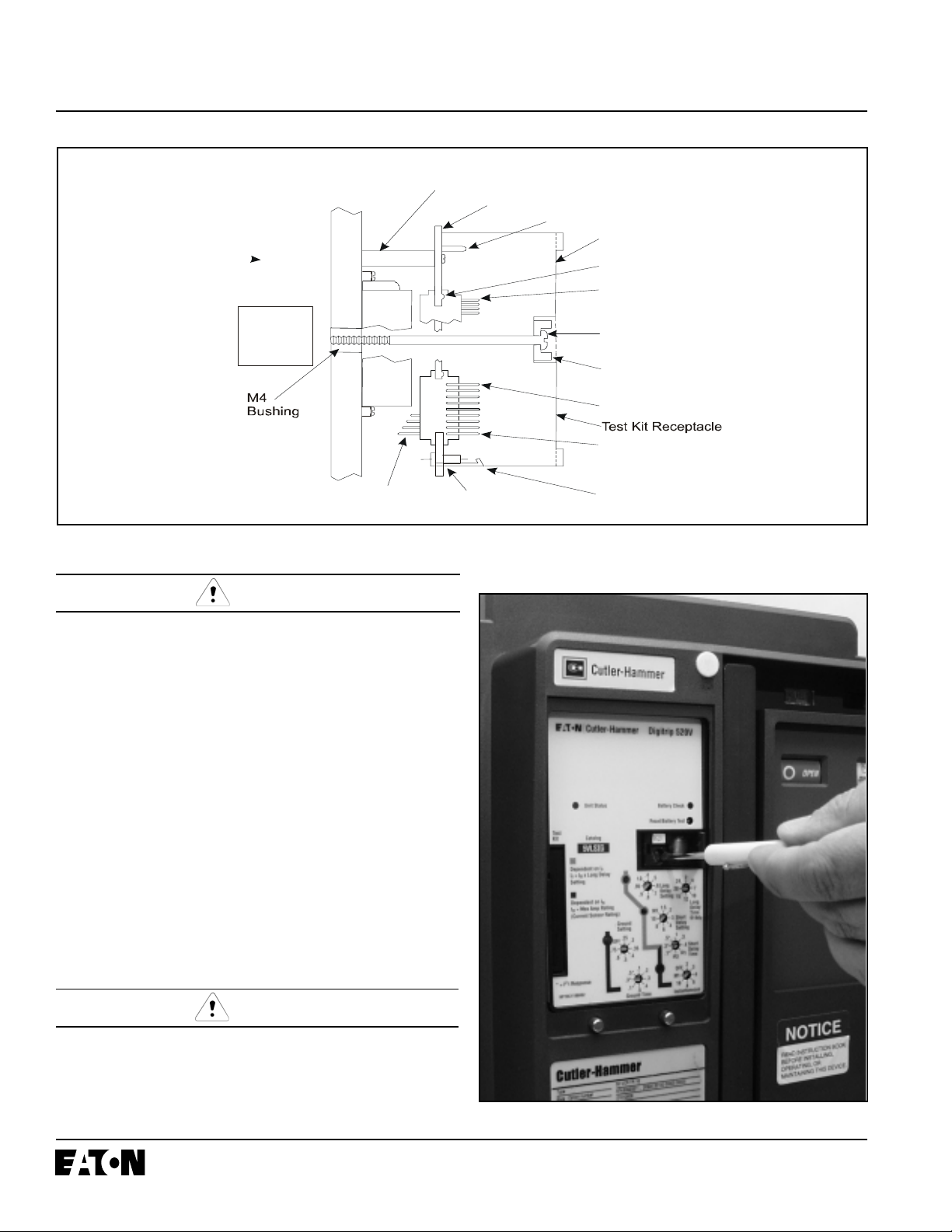
J3 (3 point)
J4 (4 point)
Connectors
Ground Alarm/Power
Supply Module
(520MCV option only)
Trip
Actuator
Mounting Boss
Steel Mounting Plate
Guide / Rejection Pin
Digitrip 520V / 520MCV
Dimple
Pin 1
Connector K2
M-4 x 80mm
Mounting Screw
Rating Plug
(3 Pins)
Pin 1 - Connector K1
0.045 Dia. Pin s Exiting
0.045 Dia. Pin s Exiting
Digitrip Housing
Digitrip Housing
I.L. 66A7534H04
Wires with
Connectors
Connector I1
Figure 1.2 Installation of the Digitrip Unit into Breaker (Side View)
CAUTION
THE M4 SCREW SHOULD BE TIGHTENED ONL Y UNTIL
IT IS SNUG BECAUSE THERE IS NO STOP. DO NOT
USE A LARGE SCREWDRIVER. A 1/8" (3mm) WIDE
SCREWDRIVER BLADE IS ADEQUA TE.
1.3.3 Trip Unit/Rating Plug Removal
T o remove the rating plug from the trip unit, make sure the
circuit breaker is open. Now open the left side of the rating
plug door. Use a 1/8" (3mm) wide screwdriver to loosen and
remove the M4x80mm mounting screw. Pull the rating plug
from the trip unit.
T o remove the trip unit from the circuit breaker , remove the
breaker cover screws using a 10mm driver. Deflect the
spring clip under the trip unit to release the unit from the
steel mounting plate. Pull the unit straight forward to
disengage the two 9-pin connectors from the circuit breaker
control circuit. (See Figure 1.2).
Spring Clip
CAUTION
DO NOT FORCE THE RATING PLUG INT O THE CA VITY .
USE A 1/8" (3MM) WIDE SCREWDRIVER TO TIGHTEN
THE M4 SCREW AND SECURE THE PLUG AND THE
TRIP UNIT TO THE CIRCUIT BREAKER (See Figure 1.3).
CLOSE THE RA TING PLUG DOOR.
Figure 1.3 Installating the Rating Plug & Mounting Screw
Effective 8/2006
I.L. 66A7534H04
Page 5
1.4 Installing the CH Type-V Current Sensors
The internal components of the circuit breaker, and how
they are wired out to the breaker secondary contacts are
shown in Figures 1.4, 1.5, 1.6 and 2.3. Also refer to the
master connection diagram provided in Appendix C.
1.4.1 Installation Procedure
The CH T ype-V Current Sensors/Rating Plug Kit supplied
with this breaker must be installed and wired by the user .
The installation steps are as follows:
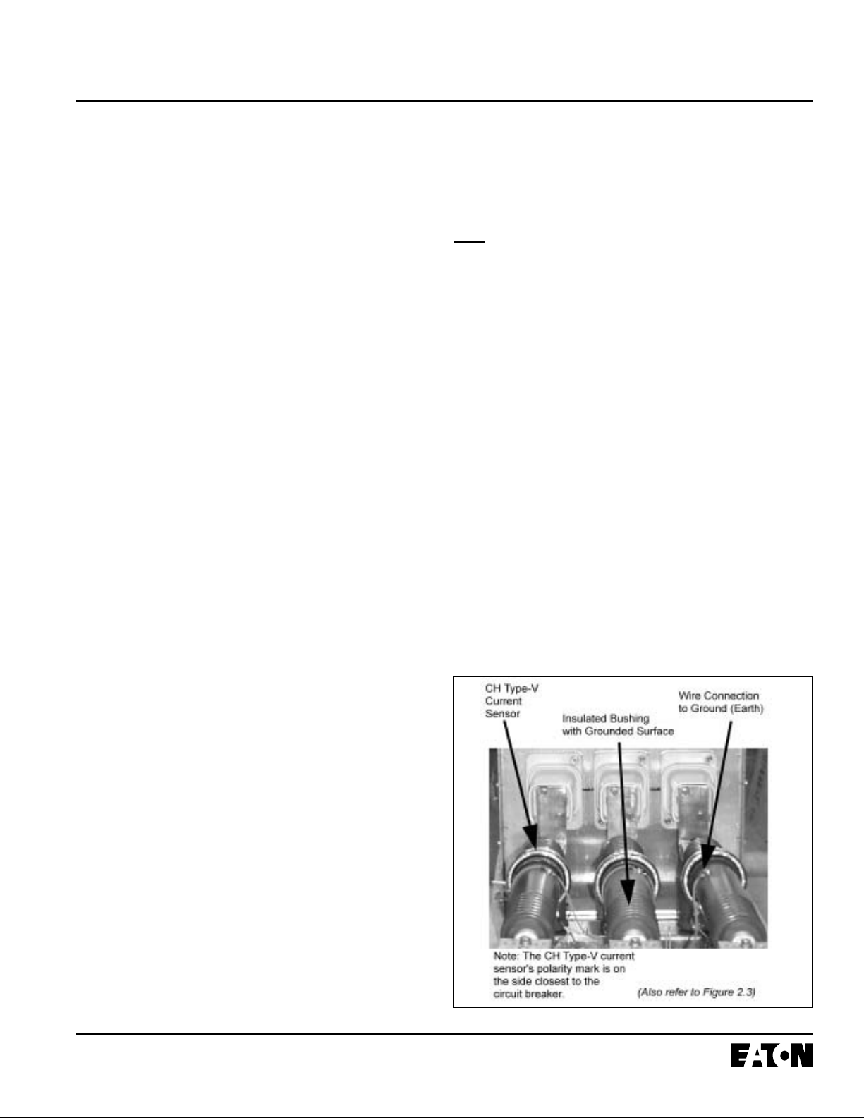
a. PRIMARY - Mount one CH T ype-V current sensor on the
insulated bushing behind the circuit breaker . The bushing
must be rated for the system Lightning Impulse Withstand
Volt age (LIWV), and the ground (earth) shield terminal or
ground (earth) shield surface must be connected to the
ground (earth) bus. Confirm that the polarity mark (red dot)
on the front of the current sensor faces the circuit breaker.
b. SECONDARY - Connect secondary terminals of the
current sensor to the correct terminals in the switchgear
control circuit using #14 A WG T ype SIS wire. Terminal X1
is the one nearest to the polarity mark. Refer to Appendix
C for distinction between Fixed and Drawout variations.
Consult manufacturer if length of wire to device exceeds 12
feet (3.7m).
c. Use ring terminals on current sensor terminals. Use
AMP #66598-2 female sockets to connect to breaker’s
secondary connector.
d. Ground (Earth) the non polarity terminal of each sensor.
Also Ground the bushing shield surfaces.
circuit breaker when functional protection settings are
exceeded.
If the CH T ype-V current sensors and circuit breaker
enclosure label are changed to a different ratio, the rating
plug must also be changed. The associated rating plug
must match the current sensors installed and as specified
on the circuit breaker enclosure label. Refer to Figure 2.3
for CH T ype-V current sensors available.
1.5 Plexiglass Cover
A clear , tamper-proof, plexiglass door sits on the breaker
cover. This door allows the settings to be viewed but not
changed, except by authorized personnel. The plexiglass
cover meets applicable tamper-proof requirements. The
cover is held in place by two screws. Security is insured
by the insertion of a standard meter seal through the holes
in both of the cover retention screws. The plexiglass cover
has an access hole for the Reset/Battery T est push
button.
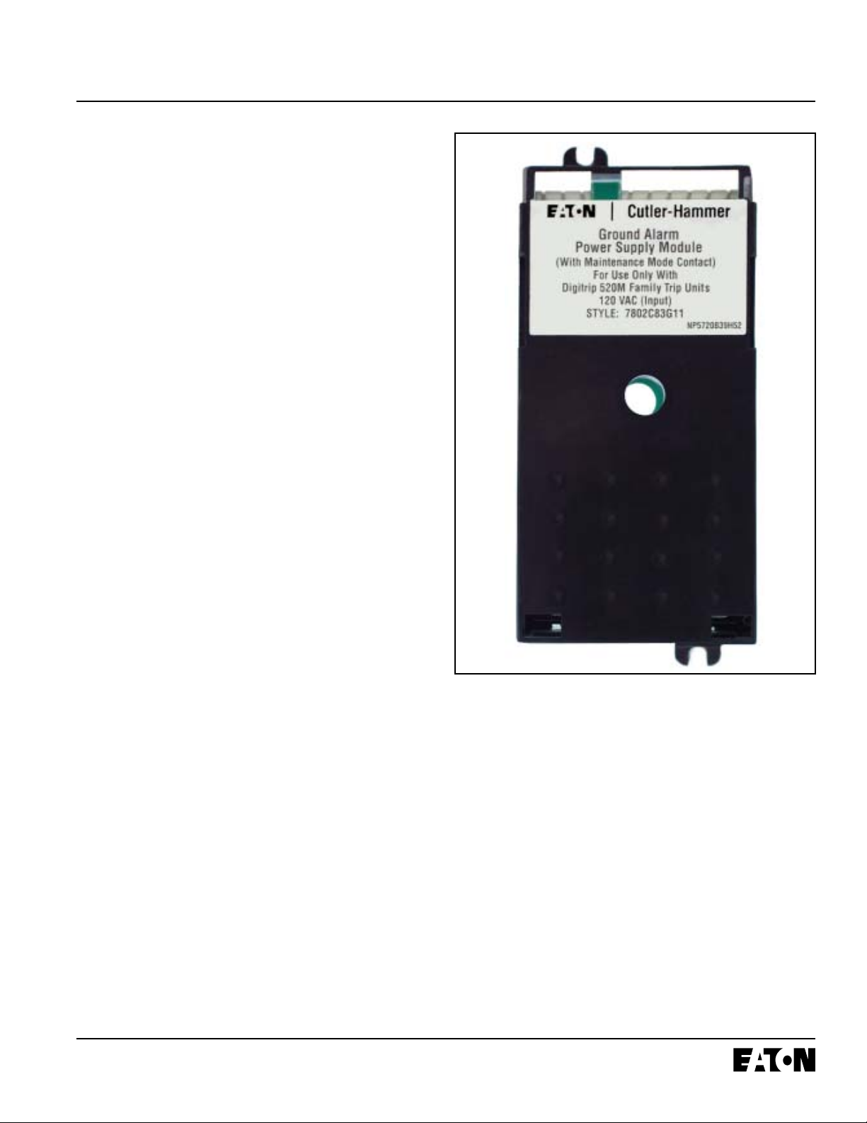
1.6 Ground Alarm/Power Supply Module (520MCV
Models Only)
The Ground Alarm/Power Supply Module (See Figure 1.7)
is a required accessory to enable communications on the
Digitrip 520MCV model. The module can be installed
beneath the metal mounting plate of the trip unit in the
Magnum Circuit Breaker. The module covers the following
input voltage ratings: 120 V AC (7802C83G1 1), 230 V AC
(7802C83G12), 24-48 VDC (7802C82G12) and 125VDC
(7802C8213). The burden of the Power/Relay Module is
10VA.
e. Install rating plug into the Digitrip 520V and 520MCV trip
units for the matching CH T ype-V current sensors. Also
attach the additional rating plug label to the circuit breaker
enclosure as a future reference indicating which CH T ype-V
current sensors used in this application.
1.4.2 CH Type-V Current Sensor Functionality
The three CH Type-V current sensors are inst alled external
to the circuit breaker over the main circuit conductors by
means of bushings equipped with a ground shield. The
current sensor rating defines the breaker rating (In)... i.e.
1200A:1A sensors are used on a 1200A rated breaker .
There are four auxiliary current transformers with a ratio of
10:1 which further step down the rated current to 100 milliamperes, which is equivalent to 100% (In) to the Digitrip.
The primary current sensors produce an output signal
proportional to the load current and furnish the Digitrip trip
units with the information and energy required to trip the
Effective 8/2006
Figure 1.4 CH T ype-V Current Sensor Installation
Page 6
I.L. 66A7534H04
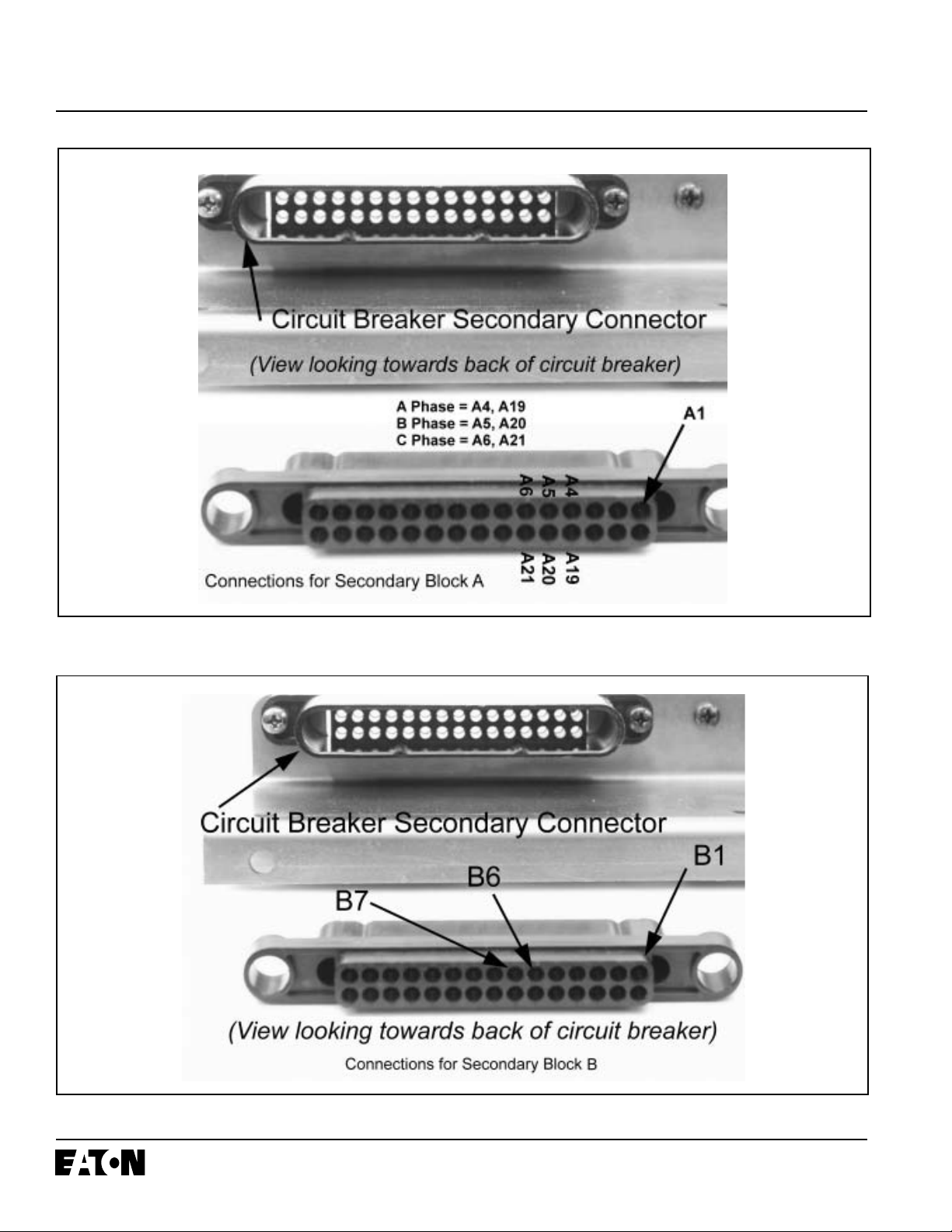
Figure 1.5 Secondary Block “A” Connections
Figure 1.6 Secondary Block “B” Connections
Effective 8/2006
I.L. 66A7534H04
1.6.1 Auxiliary Power
When the module is wired as shown in Figure 1.8, it will
provide an auxiliary power supply so that the 520MCV
liquid crystal display (LCD) will be functional even when the
circuit breaker has no load. A Digitrip 520MCV tripunit
without auxiliary power will not display data until load
current reaches approximately 30% 1 phase or 10%
3 phase of the (In) rating.
1.6.2 Ground Alarm
A second function of the module is to provide either a
ground trip or ground alarm only output contact via the
relay supplied in the module. An LED on the front of the
unit also provides an indication of ground fault trip.
1.6.3 Ground Fault Trip
When the Ground Alarm/Power Supply module is used,
this unit will provide ground fault trip contacts when the
circuit breaker trips on a ground fault. You must then push
the Reset button on the Digitrip in order to reset the
contacts (See Figure 1.8, Note 3).
Page 7
1.6.4 Ground Fault Alarm
A ground fault alarm alerts a user to a ground fault condition without tripping the circuit breaker. A red Alarm Only
LED on the front of the trip unit will indicate the presence
of a ground fault condition that exceeds the programmed
setting.
The ground fault alarm relay is energized when the ground
current continuously exceeds the ground fault pickup
setting for a time in excess of a 0.1 second delay . The
alarm relay will reset automatically if the ground current is
less than the ground fault pickup (See Figure 1.8, Note 4).
1.7 Display Feature (520MCV only)
The Digitrip 520MCV model has a user interface in addition
to the green and red LED trip indicators. This seven
element display performs a metering function and can be
used to monitor load currents.
When the Step button on the face of the trip unit is
pressed and released, the display will show PH 1, for
Phase 1 or A, and the current value. If the S tep button is
not pressed again, the display will continue to show the
current value for Phase 1. Each time that the Step button
is pressed, the next monitored function will be displayed.
The other real time readings can be displayed in the
following sequence:
Figure 1.7 Ground Alarm/Power Supply Module for the
520MCV T rip Unit
PH 2 Phase 2 (B)
PH 3 Phase 3 (C)
PH 4 Neutral
PH 5 Ground
H I Highest phase current
OL Overload (Digitrip in overload mode)
Pushing the Step button while the unit is in the OL
mode will have the unit again display the overload
current value.
HELP This message can indicate more than one problem
with the trip unit. If the rating plug is missing, a
HELP message and an Instantaneous trip LED
light will be observed. The rating plug needs to be
installed and the Instantaneous trip LED must be
cleared by pressing the Reset/Battery Test button.
Effective 8/2006
Page 8
I.L. 66A7534H04
This message could also indicate that the trip unit
is out of calibration and should be replaced at the
earliest opportunity .
Ground
Control V oltage
2
3
Fault Trip
Remote
A-10
J3-3
J3-2
Output -
J3-1
G-Alarm
Ground Alarm / Power Supply Module
K2-3
K2-1
K2-6
G-ALM 1
Output +
1
Ground
Fault Alarm
A14
A-11
J4-4
J4-3
J4-2
ATR V o lt.
G-ALM 2
Digitrip 520MCV
1.8 UL, CSA and CE Recognition
The Digitrip 520V and 520MCV Trip Units are a UL
®
(Underwriters Laboratories, Inc.) Recognized Component
under File E146559 for use in Type VCP-T, VCP-TR and
Type T-V AC, T-V ACR Medium V oltage Circuit Breakers.
They have also been tested by the Canadian Standards
Association (CSA).
This Digitrip 520V and 520MCV have also passed the IEC
947-2 test program which includes radiated and conducted
A-15
J4-1
ATR CO M
emissions testing. As a result, all units carry the CE mark.
Co ntact Ra ting (r esist ive lo a d)
1
AC 0.5A @ 230VAC
Available
Input Voltages
120 VAC
230 VAC
24-48 VDC
125 VDC
Style
Number
7802C83G01
7802C83G02
7802C82G02
7802C82G02
7802C82G03
2
AC 1A @ 120VAC
DC 1A @ 48VDC
DC 0.35A@ 125VDC
Verify input voltage rating before energizing circuit.
2
When used in conjunction with a T. U. Cat .
3
5ARMVLSIG will indicate GF trip.
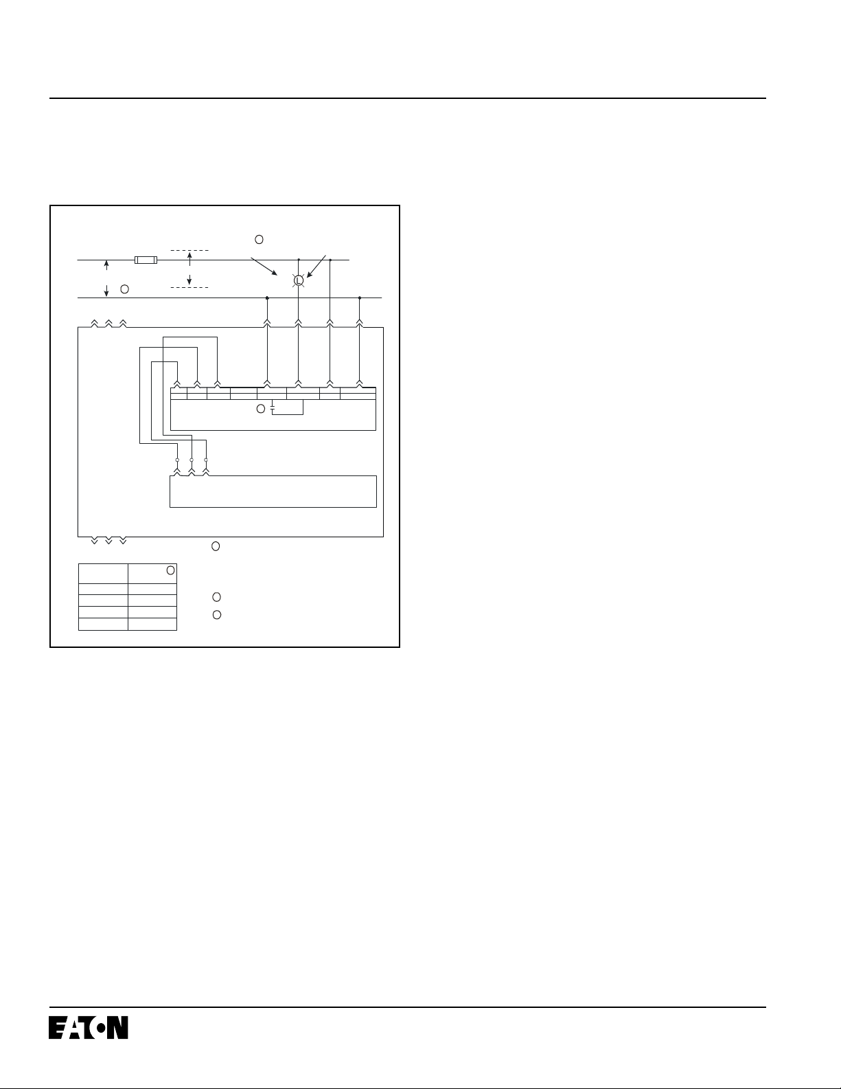
Figure 1.8 Wiring Diagram for 520MCV with Ground
Alarm/Power Supply Module
In addition, the Digitrip 520MCV will display and freeze the
magnitude of the trip value after a trip event if auxilary
power is available. Use the Step pushbutton to view each
phase value. The highest value that can be presented is
9999. Any fault current s greater than this value will be
shown as “HI.” Pushing the Reset pushbutton will clear
this data.
Also related to the phase value after a trip event are four
dashes “----”. This message means that the microprocessor could not complete its writing of the trip event’s
magnitude into its non volatile memory . A possible cause
of this would be the lack or loss of auxilary power during
the trip event.
2.0 GENERAL DESCRIPTION of VCP-T, VCP-TR or
T-V AC, T -V ACR CIRCUIT BREAKERS
2.1 General
The circuit breakers are tripped automatically on overload
and fault current conditions by the combined action of
three components:
1. The sensors, which measure the current level
2. The Digitrip Trip Unit, which provides a tripping signal to
the Trip Actuator , when current and time delay settings
are exceeded.
3. The low-energy T rip Actuator , which actually trips the
circuit breaker.
This arrangement provides a very flexible system, covering
a wide range of tripping characteristics described by the
time-current curves referenced in Section 9.2.
Effective 8/2006
I.L. 66A7534H04
Page 9
2.2 Low-Energy Trip Actuator
The mechanical force required to initiate the tripping action
of the circuit breaker is provided by a special low-energy
Trip Actuator . This device is located behind the molded
platform on which the Digitrip units are supported. (See
Figure 1.2) The T rip Actuator cont ains a permanent magnet
assembly , moving and stationary core assemblies, a
spring, and a coil. Nominal coil resistance is 25 ohms and
the black lead is positive. The circuit breaker mechanism
automatically resets the T rip Actuator each time the circuit
breaker opens.
When the T rip Actuator is reset by the operating mechanism, the moving core assembly is held in readiness
against the force of the compressed spring by the permanent magnet. When a tripping action is initiated, the lowenergy T rip Actuator coil receives a tripping pulse from the
Digitrip trip unit. This pulse overcomes the holding effect of
the permanent magnet, and the moving core is released to
upset the trip latch of the circuit breaker mechanism.
2.3 Ground Fault Protection
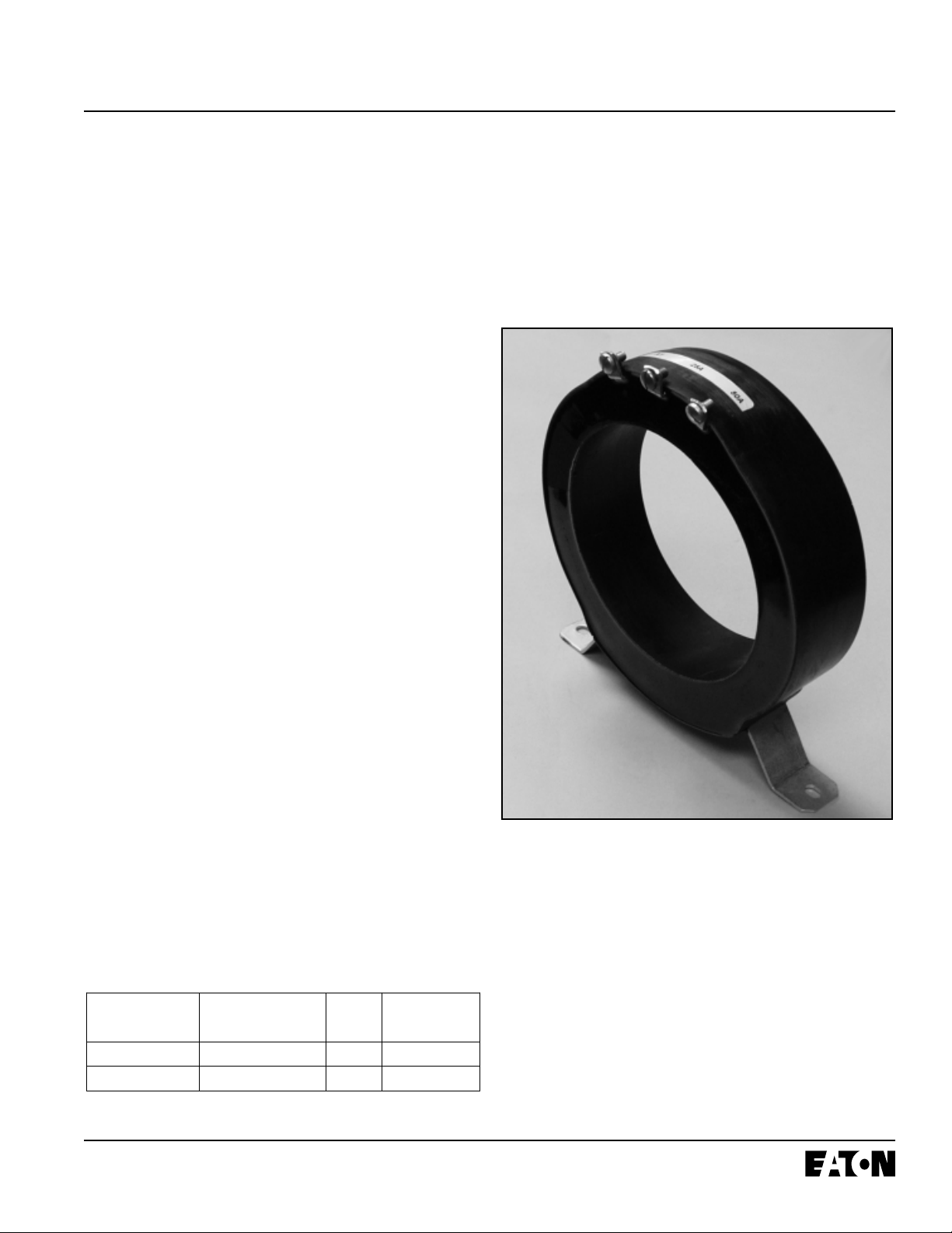
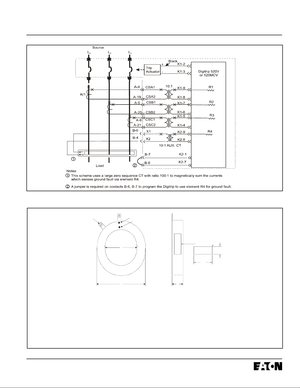
2.3.2 Zero Sequence Sensing
Zero Sequence Sensing, also referred to as vectorial
summation, is applicable to mains, feeders, and special
schemes involving zone protection. An optional CH Type-V
Zero Sequence current transformer (See Figure 2.1), having
taps for 100A and 200A ratings is available for this
application. The torroidal sensor has a 4.8” I.D. (12.192cm)
with a 7.6” O.D. (19.304cm). Its style number
69C3016G01. (See Figure 2.3 and Appendix C)
2.3.1 General
When employing a ground fault scheme, the distribution
system characteristics (i.e. system grounding, number of
sources, number and location of ground points, etc.) must
be considered along with the manner and location in which
the circuit breaker is applied to the system. These elements are discussed in Sections 2.3.2 through 2.3.4.
The Digitrip uses two modes of sensing to detect ground
fault currents: residual and zero sequence (See T able 2.1).
The breaker’s secondary contact inputs B-6, B-7, that
were shown in Figure 1.6, are used to configure the
breaker cell positions for the two schemes. Having no
jumper from B-6 to B-7 programs the unit for a residual
ground fault scheme, while installing a jumper from B-6 to
B-7 programs the unit for zero sequence configuration. If
present, this jumper resides on the stationary side of the
switchgear assembly . The proper current sensor input is
required on the external sensor input terminals B-4, B-5 of
the breaker secondary contacts.
Ground (Earth)
Fault
Sensing Method
Residual No Jumper 2.2 element R5
Zero Sequence Jumper B6 to B7 2.3 element R4
Breaker Se condary
Contacts Req’d Figure
Ref
Digitrip GF
Sensing
Element Used
Figure 2.1 Zero Sequence Current T ransformer
2.3.3 Residual Sensing
Residual is the standard operating mode of ground fault
sensing. This mode utilizes one current sensor on each
phase conductor (See Figure 2.2). If the system neutral is
grounded, but no phase to neutral loads are used, the
Digitrip includes all of the components necessary for
ground fault protection. This mode of sensing vectorily
sums the outputs of the three or four individual CH T ype-V
current sensors. Residual ground fault sensing features
are adaptable to main and feeder breaker applications.
T able 2.1 Digitrip Sensing Modes
Effective 8/2006
Page 10
A
A
A
I.L. 66A7534H04
2.3.4 Ground Fault Settings
The adjustment of the ground fault functional settings
(FLA T response or I
2
t) is discussed in Section 4.8. The
effect of these settings is illustrated in the ground fault
time-current curve referenced in Section 9. The residual
ground fault pick-up settings are from 0.25x, 0.3x, 0.35x,
0.4x, 0.5x, 0.6x, 0.75x and OFF.
Source
L
A
L
B
L
C
CAUTION
IF THE PHASE CONNECTIONS ARE INCORRECT , A
NUISANCE TRIP MA Y OCCUR. ALW A YS OBSER VE THE
POLARITY MARKINGS ON THE INST ALLA TION DRA WINGS. TO INSURE CORRECT GROUND F AUL T EQUIPMENT PERFORMANCE, CONDUCT FIELD TESTS TO
INSURE PROPER GROUND F AULT FUNCTIONALITY.
Black
K1-2
K1-3
Digitrip 520V
or 520MCV
Trip
Actuator
+
-
10:1
K1-9
K1-8
K1-7
1
K1-6
R/1
A-4
-19
A-5
-20
CSA1
CSA2
CSB1
CSB2
K1-5
R/1
A-6
-21
B-5
B-4
CSC1
CSC2
X1
X2
K1-4
K2-9
K2-8
10:1 AUX. CT
Load
Notes:
1
In this scheme, all breaker secondary currents (at the 100 mA level) are summed together at the PC
board donut transformer to sense ground fault via element R5.
2
Do not jumper secondary contacts B-6, B-7. This will defeat the residual ground fault protection.
R5
Figure 2.2 Breaker Using Residual GF Sensing
Effective 8/2006
I.L. 66A7534H04
A
B
C
100A 69C3011H01 3.42 5.35 1.55
2 X
17
1:1
0
0
200A 3.42 5.35 1.55
1
7
1
: 2
0
0
250A 3.42 5.35 1.55
1
8
1
: 2
5
0
300A 3.42 5.35 1.55
1
8
1
: 3
0
0
400A 3.42 5.35 1.55
1
7
1
: 4
0
0
600A 3.42 5.35 1.55
1
8
1
: 6
0
0
630A 3.42 5.35 1.55
1
8
1:
6
3
0
800A 3.42 5.35 1.55
1
9
1
:
80
0
1000A 3.42 5.35 1.55
1
9
1
:10
0
0
1200A 3.42 5.35 1.55
1
9
1
:12
0
0
1250A 3.42 5.35 1.55
1
9
1
:12
5
0
1600A
2000A
3.42
3.42
5.35
5.35
1.55
1.55
2
0
2
1
1:1
600
1
:
20
0
0
3.0
6
1.1
7
4
.67
7
.25
2
.
2
9
2.9
3
1
.
871
.
2
1
0.4
7
0.6
10.
5
6
0
.
310
.
0
9
R
d
c
(O
h
m
s +
/
-
1
5
%
)
RAT
I
O
W
IRE
G
A
U
G
E
C (max)B (max)A (min )DESCRIPTION
POLARITY MARK SECONDARY “X1
”
L
A
B
E
L
2
.
0
0.7
5
LA
B
EL
INF
O
R
M
A
TIO
N
:
CU
TLE
R-H
A
M
M
E
R P
A
R
T N
U
M
BER
RA
T
ING
C-
H
Ty
p
e
V
C
U
R
REN
T S
E
N
S
O
R
DA
T
E C
O
D
E (
YR
M
O
D
Y L
O
C
)
69C3011H02
69C3011H2 5
69C3011H03
69C3011H04
69C3011H06
69C3011H63
69C3011H08
69C3011H10
69C3011H12
69C3011H13
69C3011H16
69C3011H20
2 x 10-32 Bra ss
Slot Head Terminal Screws
POLARITY MARK PRIMARY “H1”
2500A
6
9C3
0
1
1
H
5
2
3.4
2
5.35 1. 55
1
: 2
5
0
0
8.9021
Page 11
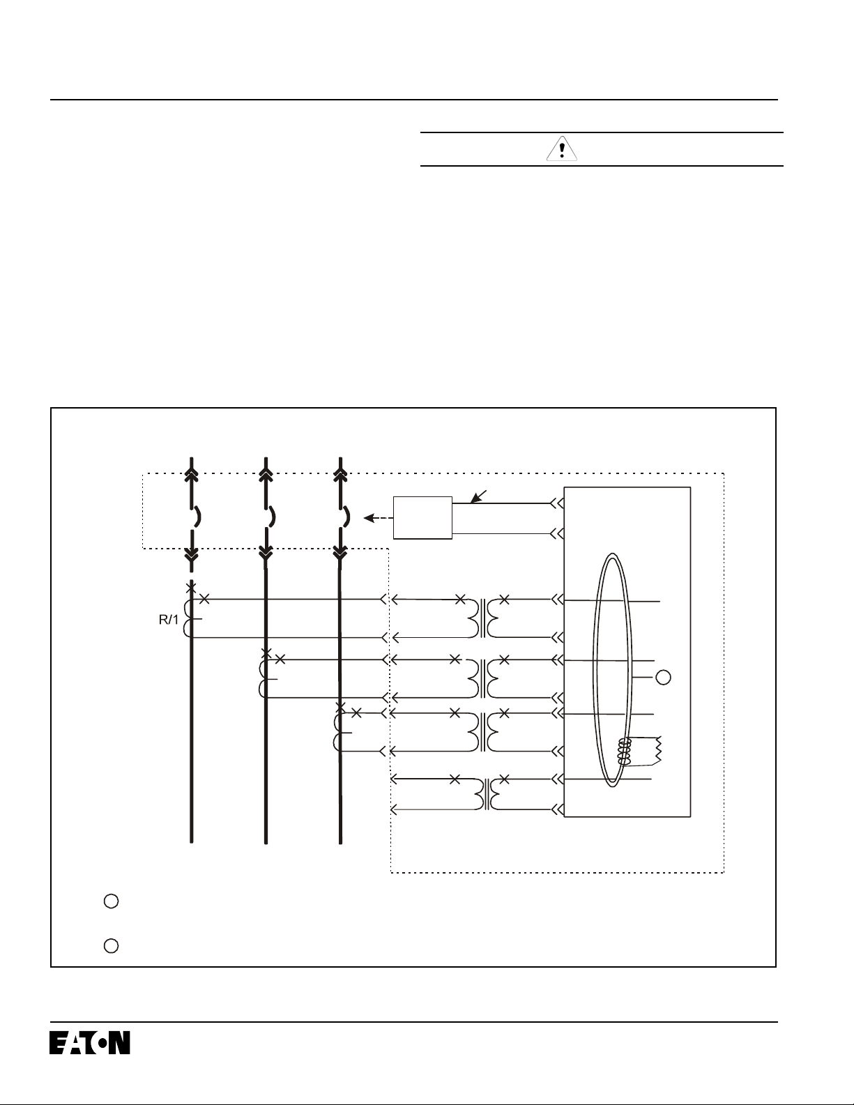
R/1
R/1
Figure 2.3 Zero Sequence Sensing Scheme
Figure 2.4 Digitrip Phase Sensor (CH T ype-V)
Effective 8/2006
 Loading...