

Eaton Digitrip 3000 series Installation, Operation And Maintenance Instructions
I.B. 17555D
INSTRUCTIONS FOR INSTALLATION, OPERATION AND MAINTENANCE OF THE
CUTLER-HAMMER DIGITRIP 3000 SERIES OF PROTECTIVE RELAYS
Supersedes I.B. 17555C dated November 1999
Effective July 2002

Supersedes I.B. 17555C dated November 1999
Effective July 2002

Supersedes I.B. 17555C dated November 1999
Effective July 2002

Instruction Leaflet DT3000
Page iv Effective: Date 07/02 I.B. 17555D
TABLE OF CONTENTS
SECTION 1: INTRODUCTION......................................................................................................................................................2
1-1 PRELIMINARY COMMENTS AND SAFETY PRECAUTIONS ............................................................................................2
1-1.1 WARRANTY AND LIABILITY INFORMATION..............................................................................................................3
1-1.2 SAFETY PRECAUTIONS .............................................................................................................................................3
1-2 GENERAL INFORMATION .................................................................................................................................................3
1-3 FUNCTIONS/FEATURES/OPTIONS ..................................................................................................................................4
1-4 STANDARDS ......................................................................................................................................................................6
SECTION 2: FUNCTIONAL DESCRIPTION.................................................................................................................................6
2-1 PROTECTION, TESTING AND COMMUNICATION CAPABILITIES ..................................................................................6
2-1.1 RMS SENSING.............................................................................................................................................................6
2-1.2 PICKUP SETTING ........................................................................................................................................................6
2-1.3 TIME SETTING.............................................................................................................................................................7
2-1.4 PROTECTION CURVE SETTINGS ..............................................................................................................................7
2-1.5 INTEGRAL TESTING .................................................................................................................................................11
2-1.6 COMMUNICATIONS ..................................................................................................................................................11
2-2 PROTECTIVE RELAY HARDWARE .................................................................................................................................14
2-2.1 FRONT OPERATIONS PANEL ..................................................................................................................................14
2-2.2 Rear Access Panel......................................................................................................................................................16
2-2.3 EXTERNAL HARDWARE ...........................................................................................................................................18
SECTION 3: OPERATION..........................................................................................................................................................20
3-1 INTRODUCTION ...............................................................................................................................................................20
3-2 POWER-UP AND SELF TESTING....................................................................................................................................20
3-3 PANEL OPERATIONS ......................................................................................................................................................20
3-3.1 CHARACTERISTIC CURVE .......................................................................................................................................20
3-3.2 PROGRAM MODE......................................................................................................................................................26
3-3.3 PROGRAMMING OVERVIEW....................................................................................................................................27
3-3.4 TEST MODE ...............................................................................................................................................................28
3-4 COMMUNICATIONS FUNCTION......................................................................................................................................28
3-4.1 ADDRESS AND BAUD RATE SETTINGS..................................................................................................................29
SECTION 4: APPLICATION CONSIDERATIONS......................................................................................................................29
4-1 ZONE INTERLOCKING CAPABILITIES............................................................................................................................29
SECTION 5: INSTALLATION, STARTUP AND TESTING .........................................................................................................32
5-1 INTRODUCTION ...............................................................................................................................................................32
5-2 PANEL PREPARATION ....................................................................................................................................................32
5-2.1 CUTOUT .....................................................................................................................................................................32
5-2.2 MOUNTING ................................................................................................................................................................32
5-3 REPLACING DIGITRIP MV WITH DIGITRIP 3000 ...........................................................................................................32
5-4 WIRING .............................................................................................................................................................................33
5-5.1 BEFORE POWER APPLICATION ..............................................................................................................................34
5-5.2 INITIAL POWER APPLICATION.................................................................................................................................34
5-6 MISCELLANEOUS TESTING ...........................................................................................................................................34
SECTION 6: MAINTENANCE AND STORAGE..........................................................................................................................34
6-1 GENERAL .........................................................................................................................................................................34
6-1.1 STORAGE ..................................................................................................................................................................34
6-2 TROUBLESHOOTING GUIDE (TABLE 6.1) .....................................................................................................................34
6-3 REPLACEMENT................................................................................................................................................................34
SECTION 7: TIME-CURRENT CURVES ....................................................................................................................................37
7-1 DIGITRIP 3000 INVERSE TIME OVERCURRENT CURVES ...........................................................................................37
7-2 DIGITRIP 3000 CURVE EQUATIONS ..............................................................................................................................61
APPENDIX A ..............................................................................................................................................................................62
A1.0 INTRODUCTION............................................................................................................................................................62
For more information visit: www.cutler-hammer.eaton.com
Supersedes I.B. 17555C dated November 1999

DT3000 Instruction Leaflet
I.B. 17555D Effective: Date 07/02 Page v
A2.0 GENERAL DESCRIPTION.............................................................................................................................................62
A3.0 INSTALLATION..............................................................................................................................................................62
A3.1 PANEL PREPARATION ..............................................................................................................................................62
A3.2 DIGITRIP 3001 DRAWOUT RELAY PARTS LIST .....................................................................................................62
A3.3 MOUNTING THE DRAWOUT OUTER CASE ............................................................................................................62
A4.0 WIRING AND SETUP ....................................................................................................................................................63
A5.0 APPLICATION CONSIDERATIONS ..............................................................................................................................67
A6.0 DRAWOUT OPERATION ..............................................................................................................................................67
A6.1 INSERTING THE RELAY ............................................................................................................................................67
A6.2 REMOVING THE RELAY ............................................................................................................................................68
APPENDIX B ..............................................................................................................................................................................69
B1.0 INTRODUCTION............................................................................................................................................................69
B2.0 GENERAL DESCRIPTION.............................................................................................................................................69
B3.0 FUNCTIONAL DESCRIPTION.......................................................................................................................................71
B4.0 INSTALLATION..............................................................................................................................................................71
B4.1 PANEL PREPARATION .............................................................................................................................................71
B4.2 MOUNTING THE DIGITRIP 3000 WITH DUALSOURCE POWER SUPPLY .............................................................71
B5.0 WIRING AND SETUP ....................................................................................................................................................73
B6.0 APPLICATION CONSIDERATIONS ..............................................................................................................................73
B6.1 SENSITIVITY AND CT RATIOS .................................................................................................................................73
B6.2 TRIPPING ON FACILITY ENERGIZATION................................................................................................................73
B6.3 CT SATURATION.......................................................................................................................................................73
B6.4 BURDEN DATA.........................................................................................................................................................75
B7.0 TESTING THE DUAL-SOURCE POWER SUPPLY.......................................................................................................75
B7.1 IN-SERVICE TEST.....................................................................................................................................................75
B7.2 LAB BENCH TEST ..................................................................................................................................................... 75
For more information visit: www.cutler-hammer.eaton.com
Supersedes I.B. 17555C dated November 1999

Instruction Leaflet DT3000
Page 2 Effective: Date 07/02 I.B. 17555D
SECTION 1: INTRODUCTION
1-1 PRELIMINARY COMMENTS AND SAFETY
PRECAUTIONS
This technical document installation, application, operation,
and maintenance of the Cutler-Hammer Digitrip 3000
Family of Protective Relays.
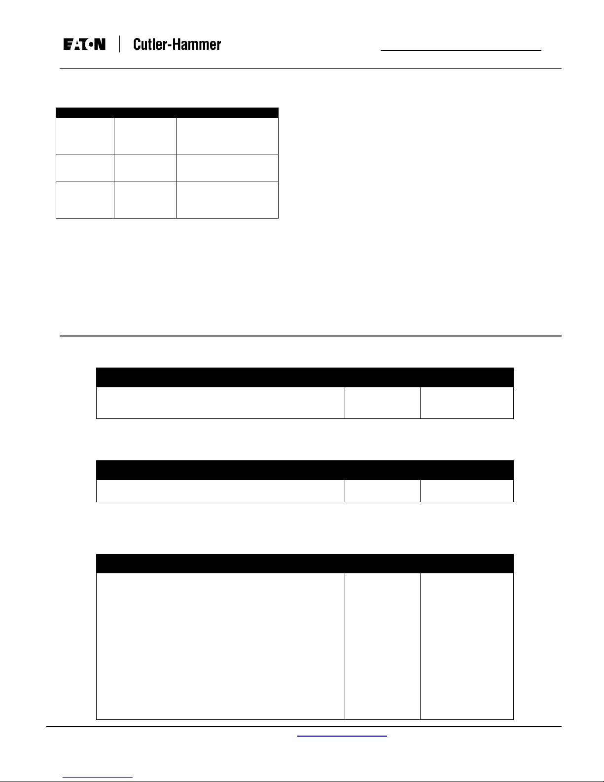
Table 1.1 shows all of the DT3000 Family products that are
covered by this Instruction Book.
The DT3001 and DT3031 Drawout Case styles
replacement parts can be ordered separately. Please refer
to Table 1.2 for a list of these style numbers.
NOTE: THE TERM “DT3000”, AS USED IN THIS
INSTRUCTION BOOK I.B. 17555D, IMPLIES TO ALL
DT3000 FAMILY PRODUCT STYLES LISTED IN
TABLES 1.1 AND 1.2. INDIVIDUAL STYLE NAMES (I.E.
DT3030, DT3031, ETC.) WILL BE USED WHERE
PRODUCT STYLES DIFFER.
Appendix A and B describe product specifics regarding the
DT3000 Drawout Case and the DT3000 Dual Source
Power Supply. THE INFORMATION PROVIDED IN THE
APPENDICES SUPERCEDES THAT IN THE MAIN
PORTION OF THIS BOOK.
DT3000 NEW
STYLE #
4D13120G21 4D13120G11 DT3000 Protective Relay – Standard FW, HR PS, PM
4D13120G22 4D13120G12 DT3100 Protective Relay – Chicago FW, HR PS, PM
4D13120G24 4D13120G04 DT3030 Protective Relay – Standard FW, LR PS, PM
4D13124G21 4D13124G11 DT3001 Protective Relay – Standard FW, HR PS, DO See Notes 1
4D13124G22 4D13124G12 DT3101 Protective Relay – Chicago FW, HR PS, DO
4D13124G24 4D13124G04 DT3031 Protective Relay – Standard FW, LR PS, DO See Notes 1
4D13125G21 4D13125G11 DT3010 Protective Relay – Standard FW, 120V DS PS, PM See Notes 2
4D13125G22 4D13125G12 DT3020 Protective Relay – Standard FW, 240V DS PS, PM See Notes 2
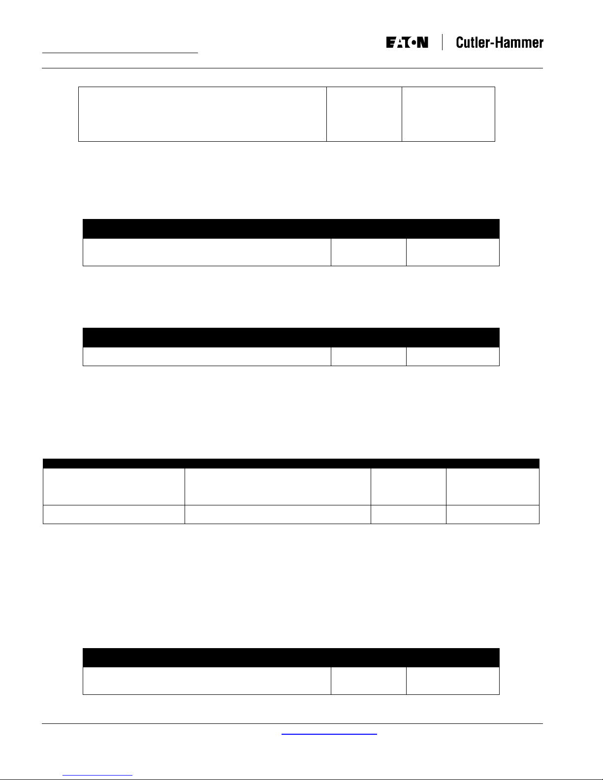
DT3000 NEW
STYLE #
66D2001G21 66D2001G11 DT3001-IC DT3001 Protective Relay – Inner Case Only See Notes 1
66D2001G22 66D2001G12 DT3101-IC DT3101 Protective Relay – Inner Case Only
66D2001G24 66D2001G14 DT3031-IC DT3031 Protective Relay – Inner Case Only See Notes 1
66D2005G21 66D2005G11 DT3001-OC DT3001 Outer Case Only
DT3000 OLD
STYLE #
DT3000 OLD
STYLE #
TABLE 1.1 DT3000 PROTECTIVE RELAY FAMILY STYLES
CATALOG # DESCRIPTION NOTES
TABLE 1.2 DT3000 DRAWOUT CASE REPLACEMENT PARTS
CATALOG # DESCRIPTION NOTES
For use with DT3XXX-IC Protective Relays
This document is provided as a guide for authorized and
qualified personnel only. Please refer to the specific
CAUTION in Section 1-1.2 before proceeding. If further
information is required regarding a particular installation,
application or maintenance activity, please contact a
Cutler-Hammer representative.
See Notes 1
Abbreviations:
DS PS = Dual Source Power Supply
LR PS = Low Range 24-48Vdc Power Supply
HR PS = High Range 120-240Vac / 48-250Vdc Power Supply
IC = Inner Chassis
PM = Panel Mount
DO = Draw Out
FW = Firmware
OC = Outer Chassis
Notes:
For more information visit: www.cutler-hammer.eaton.com
1. Additional product specifications and information in Appendix
A.
2. Additional product specifications and information in Appendix
B.
Supersedes I.B. 17555C dated November 1999
DT3000 Instruction Leaflet
I.B. 17555D Effective: Date 07/02 Page 3
1-1.1 WARRANTY AND LIABILITY INFORMATION
NO WARRANTIES, EXPRESSED OR IMPLIED,
INCLUDING WARRANTIES OF FITNESS FOR A
PARTICULAR PURPOSE OF MERCHANTABILITY, OR
WARRANTIES ARISING FROM COURSE OF DEALING OR
USAGE OF TRADE, ARE MADE REGARDING THE
INFORMATION, RECOMMENDATIONS AND
DESCRIPTIONS CONTAINED HEREIN.
In no event will Cutler-Hammer be responsible to the
purchaser or user in contract, in tort (including negligence),
strict liability or otherwise for any special, indirect, incidental
or consequential damage or loss whatsoever. Including but
not limited to damage or loss of use of equipment, plant or
power system, cost of capital, loss of power, additional
expenses in the use of existing power facilities or claims
against the purchaser or user by its customers resulting from
the use of the information and descriptions contained herein.
1-1.2 SAFETY PRECAUTIONS
All safety codes safety standards and/or regulations must be
strictly observed in the installation, operation and
maintenance of this device.
from dc power only) and provides true rms sensing of each
phase and ground current. Only one relay is required per
three-phase circuit. An integral part of each device is the
monitoring and the ability to select protective
current
functions.
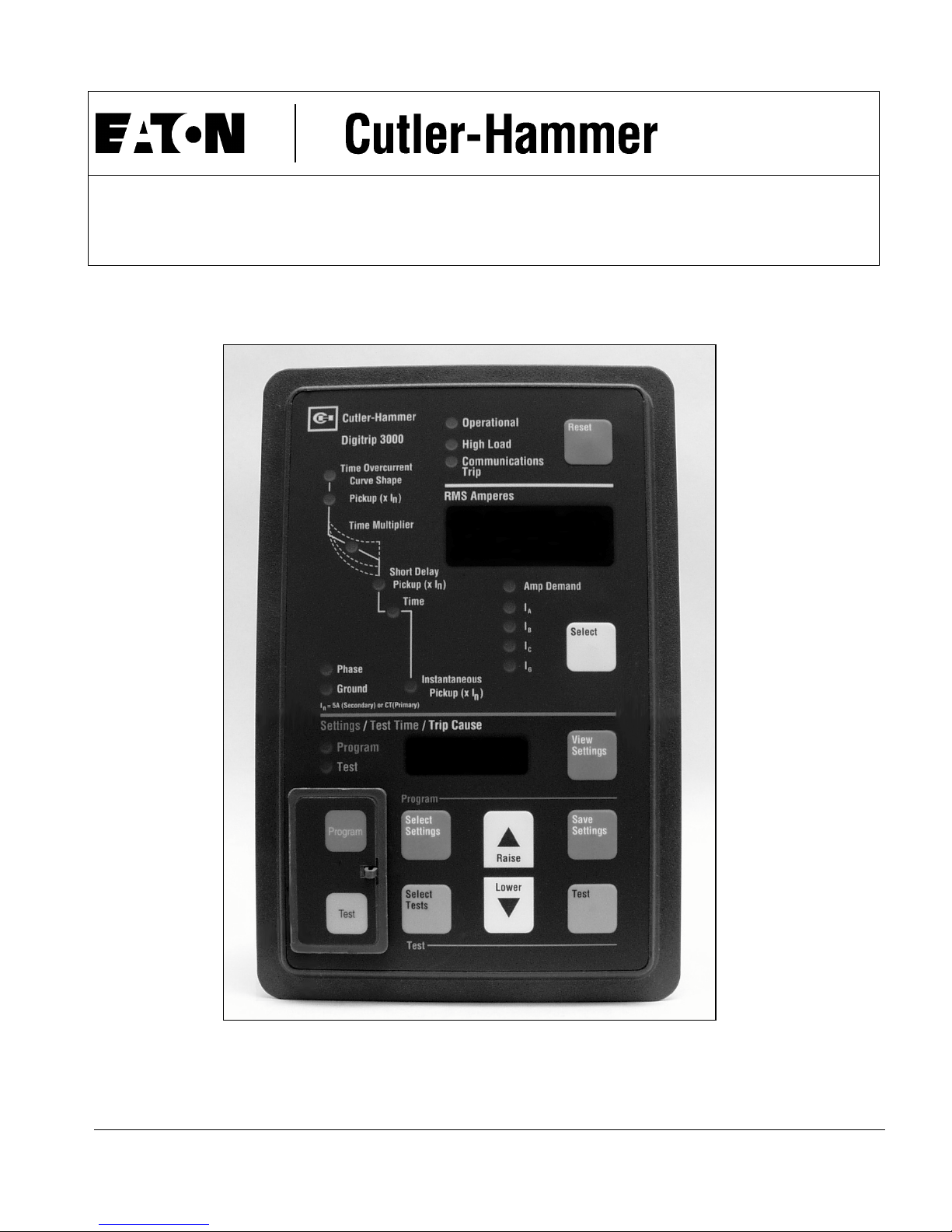
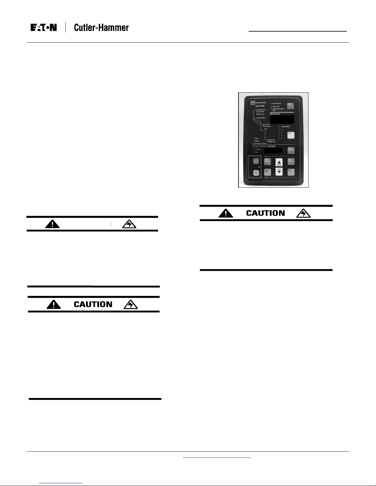
Fig. 1-1 Digitrip 3000 Protective Relay (Front View)
WARNING
THE WARNINGS AND CAUTIONS INCLUDED AS
PART OF THE PROCEDURAL STEPS IN THIS
DOCUMENTARE ARE FOR PERSONNEL SAFETY
AND PROTECTION OF EQUIPMENT FROM
DAMAGE. THIS IS AN EXAMPLE OF A TYPICAL
WARNING LABEL. THIS WILL HELP TO ENSURE
THAT PERSONNEL ARE ALERTED TO CAUTIONS
THAT APPEAR THROUGHOUT THE DOCUMENT.
COMPLETELY READ AND UNDERSTAND THE
MATERIAL PRESENTED IN THIS DOCUMENT
BEFORE ATTEMPTING INSTALLATION,
OPERATION OR APPLICATION OF THE
EQUIPMENT. ONLY QUALIFIED PERSONS
SHOULD BE PERMITTED TO PERFORM ANY
WORK ASSOCIATED WITH THE EQUIPMENT. ANY
WIRING INSTRUCTIONS PRESENTED IN THIS
DOCUMENT MUST BE FOLLOWED PRECISELY.
FAILURE TO DO SO COULD CAUSE PERMANENT
EQUIPMENT DAMAGE, BODILY INJURY OR
DEATH.
THE LOSS OF CONTROL VOLTAGE WILL CAUSE
THE DIGITRIP 3000 TO BE INOPERABLE. IF AC
CONTROL VOLTAGE IS USED, IF AC CONTROL
VOLTAGE IS USED AN APPROPRIATE RELIABLE
POWER SOURCE/SCHEME SHOULD BE
SELECTED (POSSIBLY AN UPS SYSTEM) TO
SUPPLY POWER TO THE RELAY.
The Digitrip 3000 Protective Relay provides protection for
most types of medium voltage electrical power distribution
systems. It was designed for use with Cutler-Hammer Type
VCP-W vacuum circuit breakers, as well as other medium
and high voltage circuit breakers. Digitrip 3000 Protective
Relays are compatible for use with all circuit breakers
utilizing a shunt trip coil.
Thermal curves, plus ANSI and IEC inverse time overcurrent
curves provide close coordination with both downstream and
upstream protective devices. One Digitrip 3000 Protective
Relay replaces the following conventional electromechanical
overcurrent relays: 1) an ammeter, 2) a demand ammeter, 3)
an ammeter switch, 4) in some situations, a lockout relay
switch (device 86).
All Digitrip 3000 Protective Relays include a built-in INCOM
communication capability that is compatible with the CutlerHammer PowerNet and IMPACC Systems.
1-2 GENERAL INFORMATION
The Digitrip 3000 Protective Relay is a panel mounted
multifunction, microprocessor based overcurrent relay,
designed for both ANSI and IEC applications (Figures 1-1
and 1-2). It is a self-contained device that operates from
either ac or dc control power (the DT3030 & DT3031 operate
For more information visit: www.cutler-hammer.eaton.com
Supersedes I.B. 17555C dated November 1999
Instruction Leaflet DT3000
Page 4 Effective: Date 07/02 I.B. 17555D
1-3 FUNCTIONS/FEATURES/OPTIONS
The primary function of the Digitrip 3000 Protective Relay is
overcurrent protection. This is achieved by analyzing the
secondary current signals received from the switch gear
current transformers. When predetermined current levels
and time delay settings are exceeded, the closing of trip
contact(s) is used to initiate breaker tripping.
The Digitrip 3000 Protective Relay operates from the
secondary output of standard switch gear current
transformers rated at = 5 amperes. It is configured to fit
specific distribution system requirements. The phase and
ground Ct ratios can be independently programmed over a
range of 5:5 to 5000:5. Refer to Table 2.2 for the available Ct
ratio settings.
Protective functions can also be configured with the circuit
breaker in the open or closed position. The DIP Switch S2,
located on the rear of the relay, is used to control closed
breaker settings (Figure 1-3). Refer to Paragraph 2-2.2 and
Table 5.1 for additional information.
Inverse time overcurrent protection for the phase element
cannot be disabled. This insures that all phase protection
cannot be disabled. The relay also automatically exits the
program mode, if there is no programming activity for 2-1/2
minutes. Programming and test mode security is provided by
a sealed, hinged access cover on the front of the relay.
Direct reading displays indicate the value currently being
considered, while multi-colored LED’s indicate operational
conditions and specific functions.
In addition to performing a continuous self-testing of internal
circuitry, all Digitrip 3000 Protective Relays include field
testing capabilities that are accessible from the front. To
check that all tripping features are functioning properly a test
current simulates an overload or short circuit condition. Refer
to Paragraph 2-1.5 for additional information.
The Digitrip 3000 Protective Relay provides five protective
functions for both phase and ground protection:
• Inverse Time Overcurrent Pickup
• Inverse Time Overcurrent Time Multiplier
• Short Delay Pickup
• Short Delay Time
• Instantaneous Pickup
The ground element is capable of a residual, an external
source ground or a zero sequence connection. But if ground
protection is not desired, it does not have to be connected.
Each of the protective functions is independently
programmed for various combinations to fit specific system
requirements. For protective functions not required, the relay
will allow all of the protective functions on ground and all but
the inverse time overcurrent function on phase to be
disabled. When the Digitrip 3000 is not set for an
instantaneous trip function, a true making current release
(discriminator) is available. But if it’s not desired, the
discriminator can be disabled.
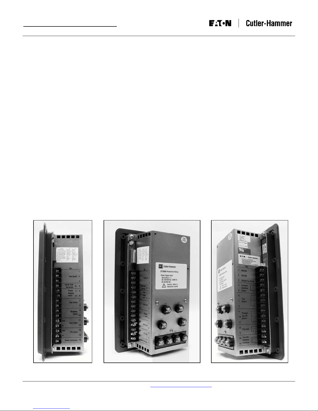
Fig. 1-2 Digitrip 3000 Protective Relay (Rear and Side Views)
For more information visit: www.cutler-hammer.eaton.com
Supersedes I.B. 17555C dated November 1999
DT3000 Instruction Leaflet
I.B. 17555D Effective: Date 07/02 Page 5
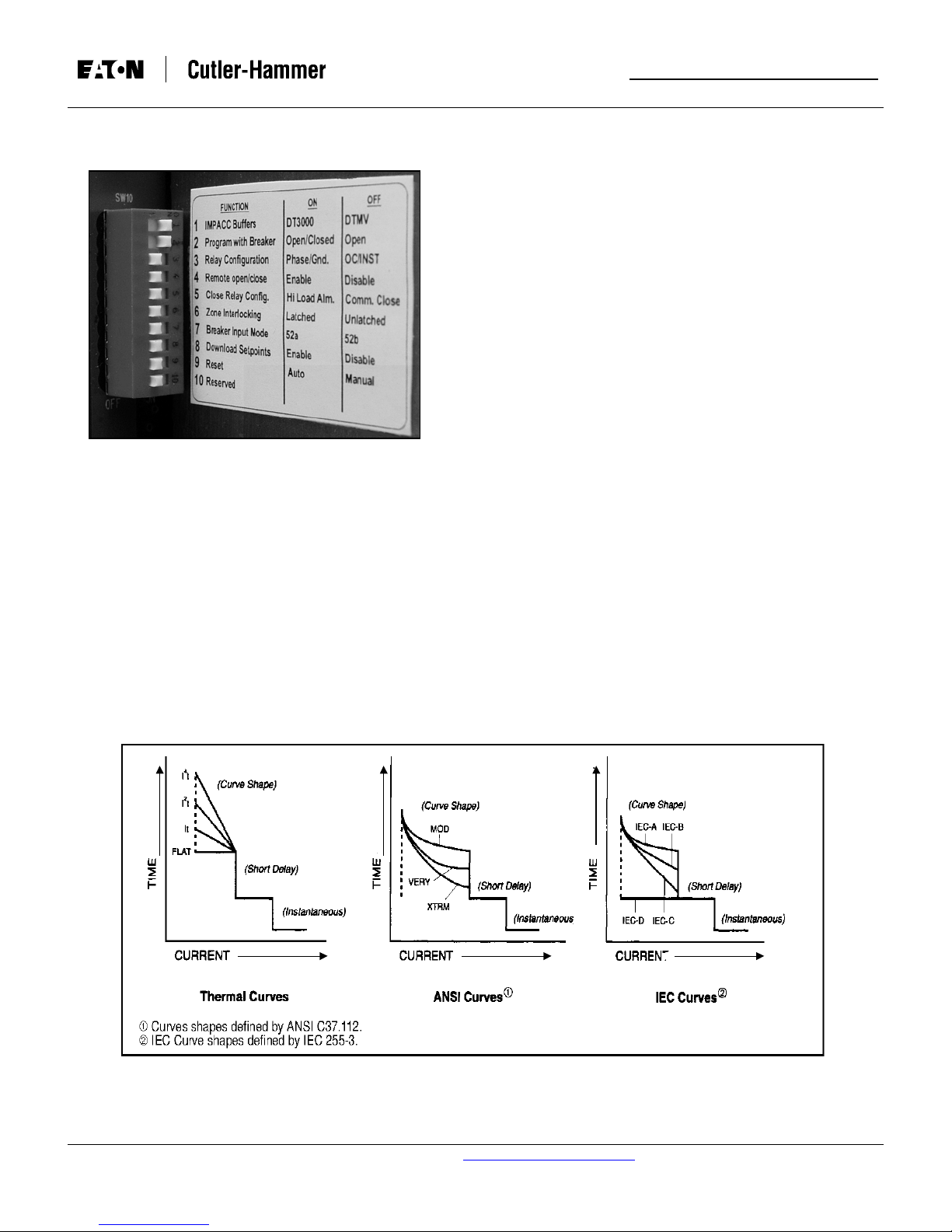
Fig. 1-3 Digitrip 3000 Protective Relay with DIP Switches
Shown in Upper Left (Rear View)
By providing 11 different curve shapes the Digitrip 3000
provides greater selective coordination with almost any
existing electromechanical overcurrent relay or power fuse.
(Figure 1-4).
- Very Inverse
- Extremely Inverse
• lEC Curves (4 shapes per IEC 255-3)
- IEC-A (Moderately Inverse)
- IEC-B (Very Inverse)
- IEC-C (Extremely Inverse)
- IEC-D (Definite Time)
The ground element of Digitrip 3000 can have a curve shape
independent of the phase element, providing for a more
versatile ground protection.
A pictorial representation of characteristic curve shapes is
provided on the face of the relay for reference purposes.
All Digitrip 3000 Protective Relays have zone selective
interlocking capabilities for phase and ground fault
protection. Zone selective interlocking is a means by which
two or more coordinated trip devices can communicate to
alter their pre-set tripping modes to provide a faster response
for certain upstream fault conditions. The relay is shipped
with the zone selective interlocking feature disabled by the
use of the two jumpers on the rear mounted terminal strip
TB1 (Figure 1-5).
• Thermal Curves (4 shapes)
- It
- I2t
- I4t
- Flat
• ANSI Curves (3 shapes per ANSI C37.112)
- Moderately Inverse
Digitrip 3000 Protective Relays operating parameters and
troubleshooting information are displayed on the front of the
relay, via the two display windows. This is considered “ON
DEVICE” information. In addition, all relay information can be
transmitted to a remote location via the built-in INCOM
communication system. This type of information is referred to
as “COMMUNICATED INFORMATION”.
For more information visit: www.cutler-hammer.eaton.com
Fig. 1-4 Digitrip 3000 Curve Shape Possibilities
Supersedes I.B. 17555C dated November 1999
Instruction Leaflet DT3000
Page 6 Effective: Date 07/02 I.B. 17555D
1-4 STANDARDS
Digitrip 3000 Protective Relays are “Component
Recognized” by the Underwriters Laboratory, Inc.® under
UL File E154862. Refer to Section 2-3 UL Testing and
Specification Summary for more information.
SECTION 2: FUNCTIONAL DESCRIPTION
2-1 PROTECTION, TESTING AND COMMUNICATION
CAPABILITIES
2-1.1 RMS SENSING
Digitrip 3000 Protective Relays provide true RMS sensing
for proper correlation with the thermal characteristics of
conductors and equipment. The root-mean-square (rms)
value is determined by a microprocessor calculation of
discrete sampled points of the current waveform. This rms
value is used for the protection response and metering
displays of the relay.
2-1.2 PICKUP SETTING
A Digitrip 3000 Protective Relay pickup setting is a
discrete, pre-selected value of current used to initiate a
tripping action. The Digitrip 3000 has several current
based tripping functions:
Fig. 1-5 Installed Jumpers in Place on Terminal Block
TB-1 Disabling the Zone Interlocking Feature
In addition to being able to provide a circuit breaker
“OPEN” or “CLOSED” status to the remote location, the
Digitrip 3000 displays and remotely transmits parameters,
such as:
• Individual phase currents
• Ground current
• Maximum current for each phase and ground since
last reset (A Demand)
• Magnitude and phase of current causing trip
• Cause of trip
• Current transformer ratio
• Existing set point settings
• Software Version
The remote communications capability is made possible by
the Cutler-Hammer Integrated Communications (INCOM)
Chip and Protocol which is compatible with the Power-Net
Monitor and Control System. Reliable two-way
communications can be provided over a twisted pair
communications network. The protocol permits a remote
master computer to perform:
1) Interrogation of relay data
2) Execution of circuit breaker “Close” and “Trip”
commands
3) “Reset” of the relay after a trip
4) Downloading of settings
• Phase inverse time overcurrent tripping - Thermal,
ANSI, and IEC Curves.
• Ground inverse time overcurrent tripping - Thermal,
ANSI, and IEC Curves.
• Phase and ground short delay tripping.
• Phase and ground instantaneous tripping.
AS SHOWN IN FIGURE 3-2, THE ANSI AND IEC
“CURVE SHAPES” ARE IN TERMS OF MULTIPLES OF
I
(PICKUP CURRENT OF THE CT PRIMARY),
PU
WHEREAS ‘SHORT DELAY’ AND “INSTANTANEOUS”
ARE IN TERMS OF MULTIPLES OF I
(5A SECONDARY
N
OF CT PRIMARY CURRENT). THE THERMAL CURVE IS
REPRESENTED IN TERMS OF MULTIPLES OF I
FOR
N
ITS CURVE SHAPE, SHORT DELAY, AND
INSTANTANEOUS SETTINGS. THIS MUST BE
CONSIDERED IN THE COORDINATION STUDY AND IN
THE PROGRAMMING OF THE DIGITRIP 3000
PROTECTIVE RELAY.
EXAMPLE: THERMAL CURVES, SHORT DELAY AND
INSTANTANEOUS SETTINGS USING I
N
Ct Rating = In = 1200A
Pickup Setting = 1.5
Pickup (amperes) = (1 200)(1 .5)
= 1800A
Example: ANSI and lEC curves using I
pu
Ct Rating = 1200A
I
= Pickup Current = 1800A
pu
For more information visit: www.cutler-hammer.eaton.com
Supersedes I.B. 17555C dated November 1999
DT3000 Instruction Leaflet
I.B. 17555D Effective: Date 07/02 Page 7
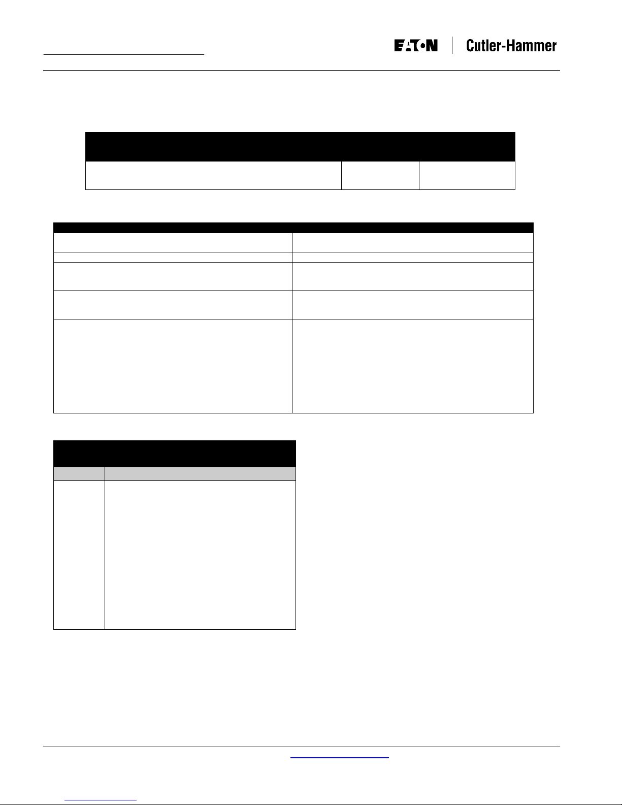
TABLE 2.1 CURVE SELECTION
Curve Type Settings Result
Thermal
ANSI
IEC
Ct Ratio = 1200:5 (Entered as “1200”)
Actual secondary current at pickup=7.5=(1800/1200) x 5
FLAT
MOD
VERY
XTRM
IEC-A
IEC-B
IEC-C
IEC-D
It
Moderately Inverse
2
t
I
Inverse
4
t
I
Extremely Inverse
Definite or Fixed Time
Moderately Inverse
Very Inverse
Extremely Inverse
Moderately inverse
Very Inverse
Extremely Inverse
Definite Time
occurs is a function of the current magnitude and the time
setting. The delay can be determined from the appropriate
time-current curves.
2-1.4 PROTECTION CURVE SETTINGS
Curve Selection: Extensive flexibility on inverse time
overcurrent (phase and ground) curve shaping is possible
with eleven available curve types. The selection and
associated result is determined by the type of curve shape
that best fits the coordination requirements (Figure 1-4,
Table 2.1). Different curve shape settings can be applied
to phase and ground to maximize coordination flexibility.
The curves are discussed in more detail in Paragraph 3-
3.1.
2-1.3 TIME SETTING
A Digitrip 3000 Protective Relay time setting is a preselected time delay initiated when a pickup point on the
long or short curve is exceeded. If the current value drops
below the pickup value, the timing function resets.
Note: The DT3000 displays pickup settings in the
“Settings” window to three significant digits only. If
there is a 4th digit in the setting, it will not be
displayed in the “Settings” window.
Memory is NOT provided. If the current value does not
drop below pickup, the amount of delay before tripping
Phase Inverse Time Overcurrent Pickup: The available pickup settings for the standard DT3000, shown below, range from
0.20 to 2.2 times (In).
Phase Element Inverse Time Overcurrent Pickup –
Available Settings
0.20, 0.25, 0.30, 0.35, 0.40, 0.45, 0.50, 0.55, 0.60, 0.65, 0.70, 0.75,
0.80, 0.85, 0.90, 0.95, 1.00, 1.10, 1.20, 1.30, 1.40, 1.50, 1.60, 1.70,
1.80, 1.90,2.00,2.10, 2.20
Tolerance Curve #
±5%
The available pickup settings for the Chicago version (DT3100 and DT3101) are shown below, they range from 0.20 to 1.00
times (I
).
n
Phase Element Inverse Time Overcurrent Pickup –
0.20, 0.25, 0.30, 0.35, 0.40, 0.45, 0.50, 0.55, 0.60, 0.65, 0.70, 0.75,
0.80, 0.85, 0.90, 0.95, 1.00
Available Settings
Tolerance Curve #
±5%
Phase Inverse Time Overcurrent Time Multiplier: The available time settings, shown below, depend on the curve shape
selected. For the thermal curves, the settings represent relay operating times at a current value equal to 3 times (In). For ANSI
and IEC curves, the settings represent the relay’s time multiplier for the current value equal to I/I
Phase Element Inverse Time Overcurrent Time Multiplier
Available Settings
Curve = IT, I2T, I4T:
0.20, 0.25, 0.30, 0.35, 0.40, 0.45, 0.50, 0.55, 0.60, 0.65, 0.70, 0.75,
0.80, 0.85, 0.90, 0.95, 1.00, 1.25, 1.50, 1.75, 2.00, 2.25, 2.50, 2.75,
3.00, 3.50, 4.00, 4.50, 5.00, 5.50, 6.00, 6.50, 7.00, 7.50, 8.00, 8.50,
9.00, 10.0, 12.5, 15.0, 17.5, 20.0, 22.5, 25.0, 27.5, 30.0, 35.0, 40.0
Curve = FLAT:
0.20, 0.25, 0.30, 0.35, 0.40, 0.45, 0.50, 0.55, 0.60, 0.65, 0.70, 0.75,
0.80, 0.85, 0.90, 0.95, 1.00, 1.25, 1.50, 1.75, 2.00
Curve = ANSI MOD, VERY, XTRM:
0.1, 0.2, 0.3, 0.4, 0.5, 0.6, 0.7, 0.8, 0.9, 1.0, 1.1, 1.2, 1.3, 1.4, 1.5,
1.6, 1.7, 1.8, 1.9, 2.0, 2.1, 2.2, 2.3, 2.4, 2.5, 2.6, 2.7, 2.8, 2.9, 3.0,
3.1, 3.2, 3.3, 3.4, 3.5, 3.6, 3.7, 3.8, 3.9, 4.0, 4.1, 4.2, 4.3, 4.4, 4.5,
4.6, 4.7, 4.8, 4.9, 5.0
Tolerance Curve #
+10%
See Notes 1 & 2
± 0.05 seconds
±10%
See Notes 1 & 2
.
pu
IT SC-5392-92B
2
T SC-5391-92B
I
4
T SC-5390-92B
I
FLAT
SC 5393-92B
MOD SC-6685-96
VERY SC-6686-96
XTRM SC-6687-96
For more information visit: www.cutler-hammer.eaton.com
Supersedes I.B. 17555C dated November 1999
Instruction Leaflet DT3000
Page 8 Effective: Date 07/02 I.B. 17555D
Curve = IECA, IECB, IECC, IECD:
0.025, 0.050, 0.075, 0.100, 0.125, 0.150, 0.175, 0.200, 0.225,
0.250, 0.275, 0.300, 0.325, 0.350, 0.375, 0.400, 0.425, 0.450,
0.475, 0.500, 0.525, 0.550, 0.575, 0.600, 0.625, 0.650, 0.675,
0.700, 0.725, 0.750, 0.775, 0.800, 0.825, 0.850, 0.875, 0.900,
0.925, 0.950, 0.975, 1.00
NOTES:
1. Curves go to constant operating time above 30 X In.
2. Tolerance: ± 10% or 0.09 seconds, whichever is larger (>1.5 x I
3. For IECD, the Time Multiplier Tolerance is ±0.05 seconds.
±10%
See Notes 1, 2 &
3
). Minimum trip time is 2 power line cycles.
pu
IECA SC-6688-96
IECB SC-6689-96
IECC SC-6690-96
IECD SC-6691-96
Phase Short Delay Pickup: The available pickup settings, shown below, range from 1 to 11 times (In) or NONE. If NONE is
selected, the short delay protective function is disabled.
Phase Element Short Delay Pickup
Available Settings
1.00, 1.25, 1.50, 1.75, 2.00, 2.25, 2.50, 2.75, 3.00, 3.50, 4.00, 4.50,
5.00, 5.50, 6.00, 6.50, 7.00, 7.50, 8.00, 8.50, 9.00, 9.50, 10.0, 11.0,
NONE
Tolerance Curve #
± 10% SC-5394-92B
Phase Short Delay Time: The available time settings, shown below, range from 0.05 to 1.5 seconds at currents equal to or
above the short delay pickup setting selected. If NONE was selected for the Phase Short Delay Pickup Setting, the relay will
bypass requesting the time setting.
Phase Element Short Delay Time (in seconds)
Available Settings
0.05, 0.10, 0.15, 0.20, 0.25, 0.30, 0.35, 0.40, 0.45, 0.50, 0.55, 0.60,
0.65, 0.70, 0.75, 0.80, 0.85, 0.90, 0.95,1.00,1.25, 1.50
Tolerance Curve #
± 0.05 seconds SC-5394-92B
Phase Instantaneous: The available pickup settings, shown below, range from 1 to 25 times (In) or NONE. If NONE is
selected, the instantaneous protective function is disabled and a choice of whether to turn the discriminator option on (DON) or
off (DOFF) is offered. The discriminator is a true making current release. When the circuit breaker closes, the discriminator
function, if selected to be on, is functional in an instantaneous trip mode for 10 cycles after the breaker closes. The breaker will
trip instantaneously via the discriminator, if the fault current is above 11 times (I
). After the 10-cycle period has passed, the
n
discriminator will no longer be functional. It becomes functional again only when the breaker opens and then is re-closed.
INSTANTANEOUS PICKUP
Type Setting Available Settings Tolerance Curve #
DISCRIMINATOR
(IF PHASE INST SET TO NONE)
1.00, 1.25, 1.50, 1.75, 2.00, 2.25, 2.50, 2.75, 3.00,
3.50, 4.00, 4.50, 5.00, 5.50, 6.00, 6.50, 7.00, 7.50,
8.00, 8.50, 9.00, 9.50, 10.0, 12.5, 15.0, 17.5, 20.0,
22.5, 25.0, NONE
D ON Fixed At 11 x In
D OFF
± 10% SC-5396-92B
+10%
Ground Fault: After the phase instantaneous setting is established, the ground curve shape, the ground inverse time
overcurrent pickup, ground inverse time overcurrent time, ground short delay pickup, ground short delay time and ground
instantaneous settings are selected. The available settings are shown below. Note that the ground curve settings are
independent of the phase curve and are programmed separately.
Programming the ground settings is done in the same manner as the phase settings, except there is no discriminator option for
ground instantaneous, and there is a NONE selection for the inverse time overcurrent pickup setting.
Ground Inverse Time Overcurrent Pickup: The available pickup settings, shown below, range from 0.20 to 2.2 times (I
Ground Element Inverse Time Overcurrent Pickup –
Available Settings
0.100, 0.125, 0.150, 0.175, 0.200, 0.225, 0.250, 0.275, 0.300,
0.350, 0.400, 0.450, 0.500, 0.550, 0.600, 0.650, 0.700, 0.750,
0.800, 0.850, 0.900, 0.950, 1.00, 1.25, 1.50, 1.75, 2.00, NONE
Tolerance Curve #
+ 5%
).
n
For more information visit: www.cutler-hammer.eaton.com
Supersedes I.B. 17555C dated November 1999

DT3000 Instruction Leaflet
I.B. 17555D Effective: Date 07/02 Page 9
Ground Inverse Time Overcurrent Time Multiplier: The available time settings, shown below, depend on the ground curve
shape setting selected. For the thermal curves, the settings represent relay operating times at a current value equal to 3 times
(I
). For ANSI and IEC curves, the settings represent the relay’s time multiplier for the current value equal to I/Ipu.
n
Ground Element Inverse Time Overcurrent Time Multiplier
Available Settings
Curve = IT, I2T, I4T:
0.20, 0.25, 0.30, 0.35, 0.40, 0.45, 0.50, 0.55, 0.60, 0.65, 0.70, 0.75,
0.80, 0.85, 0.90, 0.95, 1.00, 1.25, 1.50, 1.75, 2.00, 2.25, 2.50, 2.75,
3.00, 3.50, 4.00, 4.50, 5.00, 5.50, 6.00, 6.50, 7.00, 7.50, 8.00, 8.50,
9.00, 10.0, 12.5, 15.0, 17.5, 20.0, 22.5, 25.0, 27.5, 30.0, 35.0, 40.0
Curve = FLAT:
0.20, 0.25, 0.30, 0.35, 0.40, 0.45, 0.50, 0.55, 0.60, 0.65, 0.70, 0.75,
0.80, 0.85, 0.90, 0.95, 1.00, 1.25, 1.50, 1.75, 2.00
Curve = ANSI MOD, VERY, XTRM:
0.1, 0.2, 0.3, 0.4, 0.5, 0.6, 0.7, 0.8, 0.9, 1.0, 1.1, 1.2, 1.3, 1.4, 1.5,
1.6, 1.7, 1.8, 1.9, 2.0, 2.1, 2.2, 2.3, 2.4, 2.5, 2.6, 2.7, 2.8, 2.9, 3.0,
3.1, 3.2, 3.3, 3.4, 3.5, 3.6, 3.7, 3.8, 3.9, 4.0, 4.1, 4.2, 4.3, 4.4, 4.5,
4.6, 4.7, 4.8, 4.9, 5.0
Curve = IECA, IECB, IECC, IECD:
0.025, 0.050, 0.075, 0.100, 0.125, 0.150, 0.175, 0.200, 0.225,
0.250, 0.275, 0.300, 0.325, 0.350, 0.375, 0.400, 0.425, 0.450,
0.475, 0.500, 0.525, 0.550, 0.575, 0.600, 0.625, 0.650, 0.675,
0.700, 0.725, 0.750, 0.775, 0.800, 0.825, 0.850, 0.875, 0.900,
0.925, 0.950, 0.975, 1.00
NOTES:
1. Curves go to constant operating time above 30 X In.
2. Tolerance: ± 10% or 0.09 seconds, whichever is larger (>1.5 x I
3. For IECD, the Time Multiplier Tolerance is ±0.05 seconds.
4. For Ground Pickup ≤0.2pu: trip time tolerance is ±15%.
Tolerance Curve #
±10%
See Notes 1, 2 &
5
±0.05 seconds
±10%
See Notes 1, 2 &
4
±10%
See Notes 1, 2, 3
& 4
). Minimum trip time is 2 power line cycles.
pu
IT SC-5401-92B
I2T SC-5400-92B
I4T SC-5399-92B
FLAT
SC-5402-92B
MOD SC-6685-96
VERY SC-6686-96
XTRM SC-6687-96
IECA SC-6688-96
IECB SC-6689-96
IECC SC-6690-96
IECD SC-6691 -96
Ground Short Delay Pickup: The available pickup settings, shown below, range from 0.100 to 11 times (In) or NONE. If
NONE is selected, the short delay protective function is disabled.
Ground Element Short Delay Pickup
Available Settings
0.100, 0.125, 0.150, 0.175, 0.200, 0.225, 0.250, 0.275, 0.300,
0.350, 0.400, 0.450, 0.500, 0.550, 0.600, 0.650, 0.700, 0.750,
0.800, 0.850, 0.900, 0.950, 1.00, 1.25, 1.50, 1.75, 2.00, 2.25, 2.50,
2.75, 3.00, 3.50, 4.00, 4.50, 5.00, 5.50, 6.00, 6.50, 7.00, 7.50, 8.00,
8.50, 9.00, 9.50, 10.0, 11.0, NONE
Tolerance Curve #
+ 10% SC-5403-92B
Ground Short Delay Time: The available time settings, shown below, range from 0.05 to 1.5 seconds at currents equal to or
above the short delay pickup setting selected. If NONE was selected for the Phase Short Delay Pickup Setting, the relay will
bypass requesting the time setting.
Ground Element Short Delay Time (in seconds)
Available Settings
0.05, 0.10, 0.15, 0.20, 0.25, 0.30, 0.35, 0.40, 0.45, 0.50, 0.55, 0.60,
0.65, 0.70, 0.75, 0.80, 0.85, 0.90, 0.95, 1.00, 1.25, 1.50
Tolerance Curve #
+ 0.05 seconds SC-5403-92B
For more information visit: www.cutler-hammer.eaton.com
Supersedes I.B. 17555C dated November 1999
Instruction Leaflet DT3000
Page 10 Effective: Date 07/02 I.B. 17555D
Ground Instantaneous: The available pickup settings, shown below, range from 0.50 to 11times (In) or NONE. If NONE is
selected, the instantaneous protective function is disabled.
Ground Element Short Delay Time
(in seconds)
AVAILABLE SETTINGS
0.50, 0.55, 0.60, 0.65, 0.70, 0.75, 0.80, 0.85, 0.90, 0.95, 1.00, 1.25,
1.50, 1.75, 2.00, 2.25, 2.50, 2.75, 3.00, 3.50, 4.00, 4.50, 5.00, 5.50,
6.00, 6.50, 7.00, 8.00, 8.50, 9.00, 9.50, 10.0, 11.0, NONE
TABLE 2.2 MISCELLANEOUS SETTINGS
TYPE SETTING AVAILABLE SETTINGS
HIGHLOAD TIME
(pickup fixed @ 0.85 X Phase Time Overcurrent Setting)
FREQUENCY
PHASE CT RATIO
GROUND CT RATIO
TEST
Phase Trip
Ground Trip
Phase
Ground
Tolerance Curve #
+ 10% SC-5396-92B
0 Sec, 5 Sec, 10 Sec, 30 Sec, 1 min, 2 min, 5 min
5 min (Chicago version)
50 Hz, 60 Hz
5,10, 25, 50, 75,100,150, 200, 250, 300, 400, 500, 600, 630,
800, 1000, 1200, 1250, 1500, 1600, 2000, 2400, 2500,
3000,3200, 4000, 5000
5,10, 25, 50, 75,100,150, 200, 250, 300, 400, 500, 600, 630,
800, 1000, 1200, 1250, 1500, 1600, 2000, 2400, 2500,
3000,3200, 4000, 5000
P1, P2, P3, P4, P5, P6, P7, P8, P9, P10, P12, P14, P16
P18, P20, P22, P25
P3T, P10T, P25T
G.1, G.2, G.3, G.4, G.5, G.6, G.7, G.8, G.9, Gi, G2, G3, G4,G5,
G6, G8, G10
G1T, G3T, G10T
Table 2.3 Factory Set Defaults
Dip Switch Settings
Type Default Setting
S1 ON (Digitrip 3000 IMPACC Buffers)
S2 OFF (Program with Breaker Open
Only)
S3 OFF (Standard Relay Configuration –
OC/Instantaneous)
S4 OFF (Enable Remote Open/Close)
S5 OFF (Communications Close)
S6 OFF (Zone Interlocking Unlatched)
S7 OFF (52b Breaker Input Mode)
S8 OFF (Disable Download Set Points)
S9 OFF (Manual Reset)
S10 OFF Reserved
For more information visit: www.cutler-hammer.eaton.com
Supersedes I.B. 17555C dated November 1999
Phase Settings
Type Default Setting
Curve Shape It
2
I
T (Chicago version)
LDPU 1.0
LDT 5 seconds
40 seconds (Chicago
version)
SDPU 1.5
11 (I
) (Chicago version)
n
SDT 1.0 seconds
1.5 seconds (Chicago
version)
INST 1.75
25 (I
) (Chicago version)
n
Ground Settings
Type Default Setting
Curve Shape It
LDPU 0.5
2.0 (I
) (Chicago version)
n
LDT 5 seconds
40 seconds (Chicago
version)
SDPU 0.75
11 (I
) (Chicago version)
n
SDT 1.0 seconds
1.5 seconds (Chicago
version)
INST 1.0
11 (I
) (Chicago version)
n
DT3000 Instruction Leaflet
I.B. 17555D Effective: Date 07/02 Page 11
N.O. contacts at terminals TB2-4 and 5. These events
are reset when the current drops below the 85% level.
System Frequency Selection: Either 60Hz or 50Hz may
be selected.
Phase and Ground Ct Ratio Selection: The available Ct
ratios, shown in the above table range from 5:5 to 5000:5.
Defaults: In the unlikely event that settings are missed or
entered incorrectly, the Operational LED will blink Red and
the relay will display “PRGM” in the Settings Display
window. This means the program settings should be reentered and saved.
2-1.5 INTEGRAL TESTING
Digitrip 3000 Protective Relays have a front accessible,
integral field testing capability. This feature introduces a
selected level of internal test current to simulate an
overload or short circuit. It checks proper functioning of the
relay and verifies that curve settings have been set-up
correctly.
The integral test function provides selectable ‘Trip’ and ‘No
Trip’ test settings for both phase and ground testing. Refer
to the above tables for available test settings. The ‘P’ used
refer to a phase current test setting, while the ‘G’ refers to
a ground current test setting. ‘T’ in the table means that the
test will initiate a breaker trip. All settings are in per unit
current values times the I
rating.
value, which is the selected Ct
n
Miscellaneous Settings
Type Default Setting
DISC OFF
HILD 10 seconds
FREQ 60 Hz
CT P 500
CT G 500
High Load: The available high load time-out settings are
shown in the tables above. At a current 85% or above the
inverse time overcurrent phase setting value, the high load
function will begin timing to the time setting selected and
the High Load LED will blink. If the current drops below the
85% value, the high load timer will reset, and only start
again when the 85% value is again reached. When the
High Load Timer times out three coinciding events occur:
1. The “High Load” LED on the front of the relay lights
continuously,
2. An alarm signal is sent over the communications
network, and
3. If DipSwitch #5 is in the “On” position, the high load
alarm also closes the Communications Close Relay
For more information visit: www.cutler-hammer.eaton.com
Supersedes I.B. 17555C dated November 1999
THE TEST MODE SHOULD NOT BE USED TO
TRIP LIVE CURRENT CARRYING CIRCUITS. IF A
LIVE CURRENT OF GREATER THAN 0.1 TIMES
THE VALUE IS FLOWING IN EITHER A PHASE OR
GROUND CIRCUIT, THE TEST MODE IS
AUTOMATICALLY EXITED, ACCOMPANIED BY AN
ERROR MESSAGE IN THE SETTINGS/TEST
TIME/TRIP CAUSE WINDOW.
2-1.6 COMMUNICATIONS
An important function of the Digitrip 3000 Protective Relay
is communications and control via the Cutler-Hammer
PowerNet Protocol. It allows the combining of electrical
distribution and control products with personal computers
into a comprehensive communications and control
network.
The Digitrip 3000’s communications chip permits the
interrogation of relay data, remote tripping and closing of
breaker, the Reset of the relay after a trip, and
downloading of set points from a remote master computer.
Note: Dip Switch #5 must be in the “Off” position to
initiate a “Communications Close” command.
Communications is accomplished from the relay to the
master computer via a 115.2 kHz frequency carrier signal

Instruction Leaflet DT3000
Page 12 Effective: Date 07/02 I.B. 17555D
over a shielded twisted pair of conductors. The receiving
terminal is a remote mounted master computer (IBM
compatible). Refer to Figure 2-1 for a typical
communications wiring diagram. Ground shielding
should be provided at one place only, with the
computer end being the recommended location.
For more information visit: www.cutler-hammer.eaton.com
Supersedes I.B. 17555C dated November 1999
DT3000 Instruction Leaflet
I.B. 17555D Effective: Date 07/02 Page 13
1
2
3
4
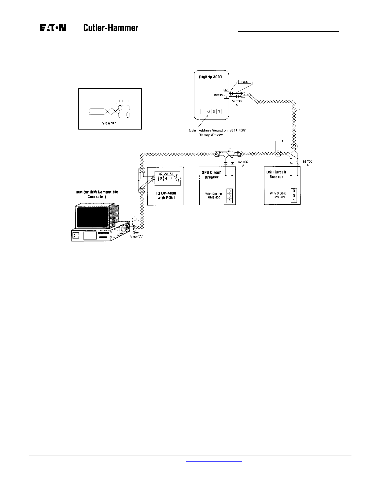
Fig. 2-1 Typical Communications Wiring Diagram
FOR NETWORK INTERCONNECTION CABLE, SEE CABLE SPECIFICATIONS ON FIGURE 3-1.
REFER TO CIRCUIT BREAKER WIRING DIAGRAMS FOR ACTUAL CONNECTIONS.
CARBON COMPOSITION RESISTOR MUST BE INSTALLED ON THE MOST REMOTE DEVICDE AS SHOWN:
- 150 OHM, ½ WATT FOR 1200 BAUD RATE COMMUNICATIONS.
- 100 OHM, ½ WATT FOR 9600 BAUD RATE COMMUNICATIONS.
A CUTLER-HAMMER CONI (COMPUTER OPERATED NETWORK INTERFACE) OR CONI-3 CARD MUST BE INSERTED INTO
THE COMPUTER ISA BUS.
CUSTOMER TO SUPPLY A COMPUTER AND MODULAR TELEPHONE CONNECTOR TYPE RJ11 AND WIRE PER VIEW A.
GROUND SHIELDING AT ONE PLACE ONLY (COMPUTER END RECOMMENDED).
WHERE DEVICES ARE DAISY CHAINED, TIE SHIELDING TOGETHER FOR END-TO-END CONTINUITY, SOME PRODUCTS
WILL PROVIDE AN EXTRA TERMINAL FOR A TIE POINT FOR THE CABLE SHIELD LEADS.
CIRCUIT BREAKER TRUCK OPERATED CELL TOC SWITCH (SHOWN FOR CIRCUIT BREAKER IN “CONNECTED” POSITION)
IS OPTIONAL TO AUTOMATICALLY DISCONNECT RELAY FROM THE COMMUNICATION NETWORK WHEN CIRCUIT
BREAKER IS IN THE “TEST” POSITION.
LAST DEVICE IN NETWORK, TIE BACK SHIELD AND TAPE.
WHEN TOC SWITCH IS USED, DOWNLOADING OF PROTECTION SETTINGS FROM THE COMPUTER WILL NOT BE
POSSIBLE WITH BREAKER IN THE “TEST” POSITION.
For more information visit: www.cutler-hammer.eaton.com
Supersedes I.B. 17555C dated November 1999

Instruction Leaflet DT3000
Page 14 Effective: Date 07/02 I.B. 17555D
2-2 PROTECTIVE RELAY HARDWARE
2-2.1 FRONT OPERATIONS PANEL
The operations panel, which is normally accessible from
the outside of the switch gear panel door, provides a
means to program, monitor and test the unit (Figure 1-1).
For the purpose of familiarization, the panel is divided into
three sub-sections:
1. Pushbuttons
2. LED’s
3. Display Windows
Pushbuttons: The front operations panel supports eleven
membrane pushbuttons. Pushbuttons are color coded (red,
white, blue and yellow) by their function. For example, blue
pushbuttons are associated with actual program functions,
yellow pushbuttons with integral testing functions, and
white pushbuttons are common to both operations or are
independent. White pushbuttons accomplish their function
when depressed. They can be held down and not released
to accelerate their function. Blue and Yellow pushbuttons
accomplish their function after having been pressed and
released.
Reset Pushbutton (Blue)
The Reset pushbutton is used to reset any of the following:
the trip relays (overcurrent and instantaneous), the trip
alarm relay, the trip LED’s, and the ampere demand
current. Reset applies to both normal operations and
integral testing. If the unit is in the auto-reset mode, as set
by DIP switch #9 on the back of the unit, the trip relays and
the trip alarm relay will automatically reset when the circuit
breaker is opened after a trip.
Program Mode Pushbutton (Blue)
The Program Mode pushbutton, which is accessed by
opening, hinged access cover, is used to enter and exit the
program mode. When this pushbutton is pressed and
released, the program LED flashes and set points can be
altered.
DIP Switch S2 establishes when the Program Mode can be
entered. With S2 set to “off,” the Program Mode can only
be entered when the breaker is open. With S2 set to “on,”
the Program Mode can be entered with the breaker open
or closed.
Selections made in the program mode are only saved
when the Save Settings pushbutton, which is described
later, is depressed. When programming is concluded, the
Program Mode pushbutton should be pressed to exit the
program mode. Note that if the Save Settings pushbutton
is not depressed prior to exiting the program mode, the
previous settings will be retained. The program mode is
also exited if the Reset pushbutton is pressed or if there is
no programming activity for approximately 2-1/2 minutes.
Note: Each Digitrip 3000 is shipped from the factory
with nominal protection settings. The user should
program the relay before putting it into service, as
For more information visit: www.cutler-hammer.eaton.com
Supersedes I.B. 17555C dated November 1999
these nominal values may not give optimum system
protection or coordination.
Test Mode Pushbutton (Yellow)
Also located behind the sealed hinged access cover is the
Test Mode pushbutton. This pushbutton is used to enter
and exit the test mode. When the pushbutton is pressed
and released, the word TEST will appear in the
Settings/Test Time/Trip Cause display window. If there is
more than 0.1 times (I
) current flowing in either the phase
n
or the ground circuit, the Test Mode cannot be initiated and
the error message “ERR” will appear in the display window.
The test mode will automatically exit if there is no activity
for approximately 2-1/2 minutes.
Select Test Pushbutton (Yellow)
The Select Test pushbutton is used, after the test mode
has been entered, to select the type of test. There are
phase and ground tests to trip or not trip the breaker (See
Section 3-3.4).
Test Pushbutton (Yellow)
The selected test operation is initiated by pressing and
releasing the Test pushbutton.
Select Settings Pushbutton (Blue)
In the program mode, the Select Settings pushbutton is
used to step to the next set point. This pushbutton steps
forward. To step back, the Select Settings pushbutton can
be pressed and held, while pressing and releasing the
Lower pushbutton.
Raise/Lower Pushbutton (White)
The Raise and Lower pushbuttons are used during the
program and test modes to increase or decrease the value
of the displayed set point.
Save Settings Pushbutton (Blue)
While in the program mode, selected Set Points can be
saved by pressing and releasing the Save Settings
pushbutton. Settings can be saved individually or as a
group. If the Save Settings pushbutton is not used, the
previous Set Points will remain when the program mode is
exited.
View Settings Pushbutton (Blue)
The View Settings pushbutton is only functional when the
unit is in the normal operating mode. It displays the unit’s
set point including the phase and ground current
transformer ratio selected via programming. The software
version of the DT3000 will be displayed after the ground Ct
ratio setting, and will appear in the rms Amperes display
window with the letters “SVER”.
Select Pushbutton (White)
The Select pushbutton is used to step between any of the
eight current values that are displayed in the rms ampere
window. The eight currents are IA, IB, IC, IG, IA ampere
demand, lB ampere demand, IC ampere demand, and IG
ampere demand. The currents displayed are the present
rms values. The ampere demand currents are the
averaged RMS values sensed over a 5-minute period of

DT3000 Instruction Leaflet
I.B. 17555D Effective: Date 07/02 Page 15
time. The demand value is the largest 5-minute average
measured since the ampere demand was last reset.
LED: LED’s are used to indicate a number of functions,
operations and/or warnings. Many of the LED’s provide
different indication messages. The color and a constant on
or blinking operation determines the specific message.
Several of the LED’s are bi-colored and can be lit green or
red.
Operational LED
The Operational LED at the top of the relay should be
green and blink on for approximately one second and then
off for one second. This indicates that the relay is
functioning properly in its normal operation mode. If this
LED is blinking red, it indicates the relay may need
reprogramming. If this LED is lit in any color shade other
than a definite green or red, or if it is not blinking at all, an
internal problem has been detected requiring replacement
of the relay.
High Load LED
The High Load LED will blink green when high load
settings are being selected in the program mode. The High
Load LED will blink red (in operational or test modes) when
a load current reaches 85% or reaches above the inverse
time overcurrent phase pick-up setting. If the load current
remains at 85% or remains above the inverse time
overcurrent phase pickup setting for the time interval
setting, the LED will change to steady red at the end of the
time interval. Whenever the load current drops below the
85% level, the timer will reset and the LED will turn off.
multiplier is being viewed in the unit’s normal operating
mode, the LED is a constant green.
Short Delay Setting LED
This LED is bi-colored and operates like the time
overcurrent setting LED.
Short Delay Time LED
The short delay time LED, when lit is green, and operates
like the inverse time overcurrent time LED.
Instantaneous LED
This LED is bi-colored and operates like the inverse time
overcurrent setting LED.
Phase LED
The phase LED is bi-colored. The LED will blink green
when the phase inverse time overcurrent setting, inverse
time multiplier, short delay setting, short delay time, and
instantaneous Set Points are displayed in the Settings/Test
Time/Trip Cause window while in the program mode.
When these Set Points are viewed in the normal operating
mode, this LED will be a constant green. The LED will blink
red, along with the time overcurrent setting LED, when the
phase load current exceeds the inverse time overcurrent
pickup set point. The LED will be a constant red, when the
phase inverse time overcurrent initiates a trip, a short
delay, or instantaneous protective functions.
Ground LED
The ground LED is also bi-colored and operates exactly
like the phase LED for all functions associated to ground.
Communication Trip LED
This LED will be a constant red when the master computer
has tripped the breaker via INCOM. The LED will turn off
when the Reset pushbutton is pressed or the circuit
breaker is re-closed.
Curve Shape LED
This LED will blink green when the slope set point is
displayed in the Settings/Test Time/Trip Cause window
while in the program mode. When the curve shape set
point is being viewed in the unit’s normal operating mode,
this LED will be a continuous green.
Time Overcurrent Setting LED
This LED is bi-colored. While in the program mode, the
LED will blink green when the inverse time overcurrent
pickup set point is displayed in the Settings/Test Time/Trip
Cause window. It will be a constant green when the inverse
time overcurrent pickup set point is being viewed in the
unit’s normal operating mode. The LED will blink red
whenever the load current exceeds the inverse time
overcurrent pickup set point. If the relay trips on inverse
time overcurrent, the LED will be continuous red.
Inverse Time Overcurrent Time LED
This LED will blink green, while in the program mode, when
the LED time overcurrent time set point is displayed in the
Settings/Test Time/Trip Cause window. When the time
For more information visit: www.cutler-hammer.eaton.com
Supersedes I.B. 17555C dated November 1999
Ampere Demand LED
This LED will be a constant green when an ampere
demand current is being viewed in the rms ampere
window.
I
, IB, IC, IG LED’s
A
The specific phase or ground current LED’s will be a
constant green when that phase or ground current is being
displayed in the rms ampere window. When the Ampere
Demand LED is also lit, the displayed current is the
Ampere Demand Current.
Program LED
This LED is a constant green when the relay is in the
program mode.
Test LED
This LED is a constant green when the relay is in the test
mode.
Display Windows: Two windows are used to display the
relay’s data, Set Points and messages. One window is
located in the upper portion of the relay’s faceplate and is
labeled RMS Amperes. A second window is located in the
lower portion of the faceplate adjacent to the program and
test LED’s. It is labeled Settings/Test Time/Trip Cause.
RMS Amperes Window
This window has a five digit numeric display and shows:
Instruction Leaflet DT3000
Page 16 Effective: Date 07/02 I.B. 17555D
1. The present phase or ground currents.
2. The largest phase or ground demand currents since
last reset.
3. The fault current (displayed after a trip until a reset
action is initiated).
4. The phase and ground current transformer Ct setting
(when “View Settings” pushbutton is used with the
relay in the normal operating mode).
Settings/Test Time/Trip Cause Window
This window is a four character alphanumeric display used
to show the value of the Set Points, the test time and the
cause of trip.
2-2.2 REAR ACCESS PANEL
WARNING
THE BACK OF DIGITRIP 3000, WHEN
ENERGIZED, OFFERS EXPOSURE TO LIVE
PARTS WHERE THE HAZARD OF A FATAL
ELECTRIC SHOCK IS PRESENT. ALWAYS
DISCONNECT SOURCE AND CONTROL POWER
SUPPLY BEFORE TOUCHING ANYTHING ON THE
REAR OF THE DIGITRIP 3000. FAILURE TO DO
SO COULD RESULT IN INJURY OR DEATH.
The rear access panel of Digitrip 3000 is normally
accessible from the rear of an open panel door. All wiring
connections to the Digitrip 3000 Protective Relay are made
at the chassis’ rear. For the sake of uniform identification,
the frame of reference used when discussing the rear
access panel is facing the back of the relay. The DIP
switches, for example, are located on the upper left of the
rear panel (Figure 1-3). Become familiar with the functions
and connections involved, especially the following:
DIP Switches: A set of ten DIP switches is located in the
upper left portion of the rear panel. Refer to Table 5.1 for
DIP switch positions. Their basic functions are as follows:
• Switch S1 is used to select whether the IMPACC
buffers are set for the Digitrip 3000 configuration or
the Digitrip MV configuration. (Refer to Section 5: for
configuring the Digitrip 3000 as a replacement for a
Digitrip MV.)
• Switch S2 is used to enable/disable the ability to
program the Set Points when the breaker is in the
open or closed position. CARE MUST BE TAKEN
WHEN PROGRAMMING THE DIGITRIP 3000 WHILE
THE BREAKER IS CLOSED AND CURRENT IS
FLOWING. AN INCORRECT SETTING
CONFIGURATION COULD CAUSE THE RELAY TO
TRIP THE BREAKER WHEN SETTINGS ARE
SAVED.
• Switch S3 is used to configure the trip contacts as
shown below:
Trip
Contacts
TB 12 & 13 Phase & Ground
TB 14 & 15 Phase & Ground
Dip Switch OFF
Position
Trip Inst.
Trip
OC/Communications
Dip Switch ON
Position
Ground Trip Inst./OC
Phase Trip Inst./OC/
Communications
• Switch S4 is used to enable/disable the ability to open
or close the breaker remotely from the
communications interface (host computer).
• Switch S5 is used to configure the Communication
Close output relay at terminals TB2-4 & TB2-5. When
S5 is in the “On” position the output relay is
programmed for High Load Alarm. When S5 is in the
“Off” position the output relay is programmed for
Communications Close.
• Switch S6 is used to configure the zone interlock
input. When the “Zone Input” switch S6 is in the “On”
position, the zone interlock input is latched for
compatibility with low voltage trip units as in the
existing DT3000. The latched Zone Interlock option
will not execute a Zone Interlock Fast Trip until the
downstream relay stops sending the zone interlock
signal and the current drops below the pickup level
settings. When switch S6 is in the “Off” position, the
zone interlock input is unlatched for faster tripping.
The unlatched Zone Interlock option executes Zone
Interlock Fast Trip when the downstream relay stops
sending the zone interlock signal. Use the latched
option for co-ordination with self-powered trip units.
Self-powered trip units stop sending the zone interlock
signal when the trip signal is issued. Latching of the
DT-3000 zone interlock input provides the needed coordination time for the downstream breaker to open.
• Switch S7 is used to select between a 52a and a 52b
input to determine breaker state. When S7 is in the
“On” position, the breaker status is based on the 52a
input. When S7 is in the “Off” position, the breaker
status is based on the 52b input. The OFF/52b
configuration is the default mode. The breaker state
determination is used for the following purposes in the
DT3000:
1. Test the number of cycles the breaker has been
closed for Discriminator operation.
2. Determine the breaker state for setting change
permission if S2 is set to “Program with Breaker
Open Only”.
3. Report breaker state to PowerNet.
The 52b contact is open when the breaker is closed
and closed when the breaker is open. The 52a
contact is closed when the circuit breaker is closed
and open when the breaker is opened or racked out.
The 52a option has the benefit of properly reporting
breaker state when the circuit breaker is racked out.
For more information visit: www.cutler-hammer.eaton.com
Supersedes I.B. 17555C dated November 1999

DT3000 Instruction Leaflet
I.B. 17555D Effective: Date 07/02 Page 17
• Switch S8 is used to enable/disable the ability to
download Set Points from the communication interface
(host computer).
• Switch S9 is used to select whether the relay should
be self-reset or manually reset (lock out function). For
additional information please refer to the “Manual
Reset”
and “Auto Reset’ sections.
In the manual reset mode the Trip Instantaneous
contact (TB2 12 and 13), Trip Overcurrent contact
(TB2 14 and 15) and the Trip Alarm contact (TB2 6, 7
and 8) change state after a protection trip operation.
The contacts stay in that state until the “Reset”
Pushbutton is pressed. In addition, the front panel will
hold the cause of trip in the “Trip Cause” window and
the fault current magnitude in the “RMS Ampere”
window. A RESET COMMAND can be sent to the
Digitrip 3000 by a master computer to remotely reset
the Digitrip 3000.
In the auto reset mode the Trip Instantaneous
contacts (TB2 12 and 13), or Trip Overcurrent
contacts (TB2 14 and 15) are momentarily closed after
a protection trip operation. The contacts will remain
closed until the current drops below 0.5 A. The Trip
Alarm Relay, however, remains energized until the
“Reset” Pushbutton is depressed or a RESET
COMMAND is received from a communication system
master. In this mode after a trip is initiated and the
current is removed, the display will BLINK the cause of
the trip in the “Trip Cause” window and the “RMS
Ampere” window will show the fault current magnitude.
Both displays clear when current is reapplied.
Terminals 11 and 12 are used for ground zone
interlocking, inverse time overcurrent protection and short
delay protection. The zone interlocking function is a low
level dc signal used to coordinate with “downstream” and
“upstream” breakers that see or do not see the fault. If the
function is not used but an inverse time overcurrent or
short delay time is desired, the two terminals should stay
jumpered as they were when shipped from the factory.
Terminals 13 and 14 are used for phase zone interlocking,
inverse time overcurrent protection and short delay
protection.
Terminal 15 is the zone signal common. Zone common
should never be connected to earth ground. Refer to
Figure 4-1 for a typical phase zone interlocking / wiring
scheme.
NOTE: DIGITRIP 3000 PROTECTIVE RELAYS ARE
SHIPPED WITH A PHASE ZONE INTERLOCKING
JUMPER (ACROSS TERMINALS TB 1-13 AND 14) AND
A GROUND ZONE INTERLOCKING JUMPER (ACROSS
TERMINALS TB 1-11 AND 12). FOR PHASE OR
GROUND ZONE CAPABILITY, THE RESPECTIVE
JUMPERS MUST BE REMOVED.
Terminal Block Two (TB2): TB2 is located on the right
side of the rear panel and is numbered 1 through 15.
Terminals 1 and 2 are used for the internal INCOM
communications interface.
Terminal 3 is used to reference the INCOM cable shield. It
is capacitively tied to ground for high frequency noise
immunity purposes.
• Switch S10 is reserved.
Inverse Time Overcurrent Reset: The inverse-time
overcurrent function in the DT3000 requires the measured
current to be below pickup for 4 cycles before the trip
accumulator is reset. The multi-cycle reset counter
eliminates concern that the integration will reset during an
arcing fault and slow down tripping.
Communicating LED: A red LED just above terminal
block (TB2) is used when the relay is communicating. If the
relay is the type designed to accept field installation of a
communication module at a later date, this LED is not
functional at any time.
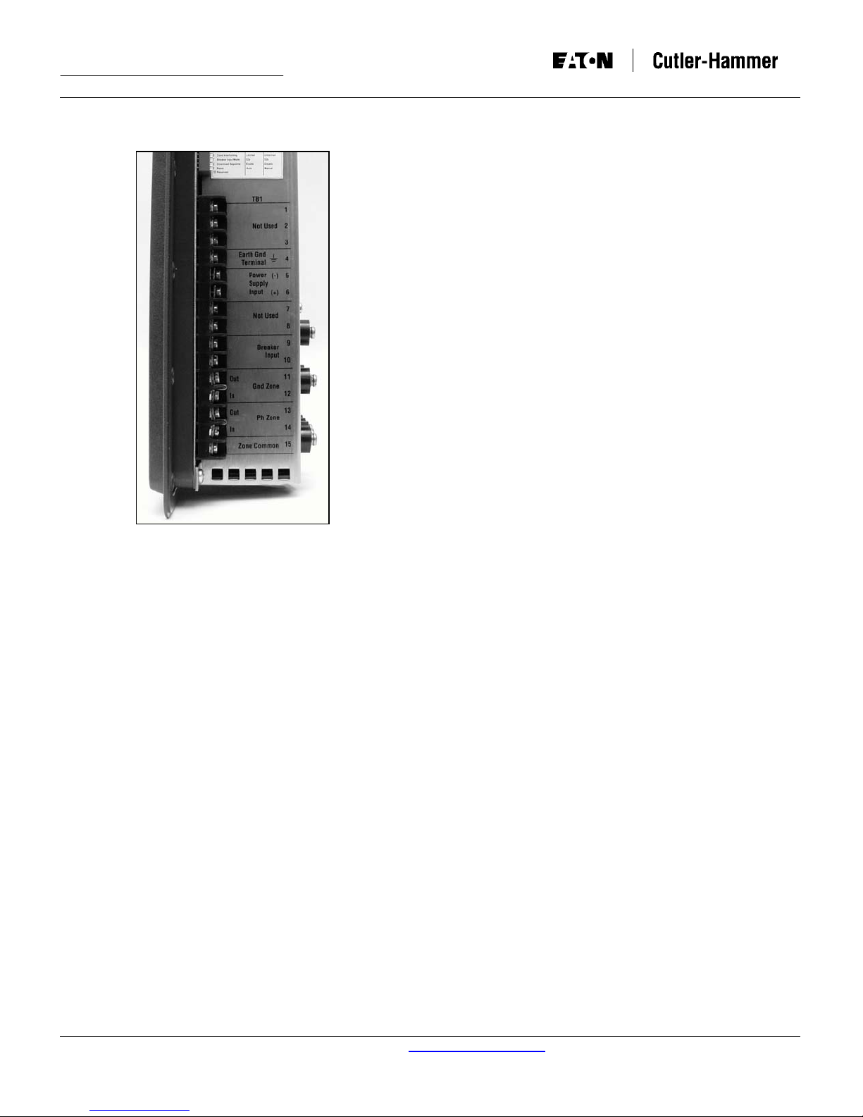
Terminal Block One (TB1): TB1 is located on the left side
of the rear panel, and is numbered 1 through 15, with 1, 2,
3, 7 and 8 not used. Terminals 5 and 6 are provided for
the AC or DC input control power connections. Terminal 4
is the connection for equipment ground. Terminal 9 and
10 provide for connection to a required dry 52b contact and
to a 52 TOC contact from the circuit breaker. When the
relay has input control power, Terminals 9 and 10 will
have this potential on them.
For more information visit: www.cutler-hammer.eaton.com
Supersedes I.B. 17555C dated November 1999
Terminals 4 and 5 are a N.O. contact from the
Communications Close output relay that can be configured
two different ways:
1. When Dip Switch S5 is in the “On” position, this output
relay is programmed to close when the High Load
timer times out.
2. When Dip Switch S5 is in the “Off” position the
Communications Close Relay can be energized via a
specific communications message sent over the
INCOM port.
Terminals 6, 7 and 8 are Form “C” contacts on the trip
alarm relay and change state whenever any protective trip
is initiated by the relay. They do not change state when the
master computer initiates an opening of the circuit breaker
via the communication interface. After a protective trip, the
contacts remain in the changed state until the “Reset”
Pushbutton is pressed, whether the relay is in Manual
Reset Mode or Auto Reset Mode.
Terminals 9,10 and 11 are Form “C” contacts on the
protection off alarm relay. The contacts change state when
nominal control power is applied to the relay and no
internal errors are detected.

Instruction Leaflet DT3000
Page 18 Effective: Date 07/02 I.B. 17555D
Terminals 12 and 13 are a “NO” configurable contact. DIP
Switch S3 is used to configure the trip contacts. With DIP
Switch S3 in the “OFF” position, this contact closes when
the relay detects a need for the circuit breaker to trip due
to either a phase or ground instantaneous fault or the
discriminator function. With DIP Switch S3 in the “ON”
position, this contact closes when the relay detects a need
for the circuit breaker to trip due to any type of ground
fault.
Terminals 14 and 15 are also a “NO” configurable contact.
With DIP Switch S3 in the “OFF” position, this contact
closes when the relay detects a need for the circuit breaker
to trip due to an inverse time overcurrent or short time
function. The contact also operates when the
communication interface initiates an action to open the
circuit breaker. With DIP Switch S3 in the “ON” position,
this contact closes when the relay detects a need for the
circuit breaker to trip due to any type of phase fault or
communications.
Rear Surface Terminals: The rear surface terminals,
identified as (A1, A2), (B1, B2), (C1, C2) and (G1, G2)
provide the current transformer input connection points
and are rated for 5 ampere inputs. (A1, A2), (B1, B2) and
(C1, C2) are phase A, B, C current inputs respectively,
while (G1, G2) is the ground current input.
2-2.3 EXTERNAL HARDWARE
The Digitrip 3000 Protective Relay requires that a
customer supplied source of input control power be wired
into the TB1 terminal block located on the rear panel.
Refer to the typical wiring diagram in Figure 3-1. A power
supply can be either ac or dc voltage within the acceptable
voltage ranges outlined in “UL Testing and Specification
Summary.”
For more information visit: www.cutler-hammer.eaton.com
Supersedes I.B. 17555C dated November 1999
2-3 DT3000 AND DT3030 SPECIFICATIONS AND TEST SUMMARY
COMPLIANCE TESTING:
Certifications:
• CUL/UL Recognized, File # E154862
• CAN/CSA C22.2 No. 14-M91 Industrial Control Equipment
• UL 1053 (6
• ANSI C37.90 (1989)
• EN 61010-1 (1993) - DT303X Models Only
• EN 55011 (1991)
• CE Compliant - DT303X Models Only
Emission Tests:
• EN 55011 (1991) - Group 1 Class A
• FCC 47 CFR Chapter 1 - Part 15 Subpart b Class A
Immunity Tests:
• ANSI C37.90.1 (1989) – Surge Withstand Capability 2.5KV
OSWC, 4KV FTSWC
• ANSI C37.90.2 (1995) – RF Radiated Withstand Capability
to 35V/M – all models
• EN61000-4-2 (1995) – ESD Immunity to 8KV
• IEC 255-22-2 (1989) - ESD Immunity to 8KV
• EN61000-4-3 (1995) – RF radiated Immunity to 10V/M
• IEC 255-22-3 (1989) - RF radiated Immunity to 10V/M
• EN61000-4-4 (1995) - Electrical Fast Transient Immunity to
10V/M
• IEC 255-22-4 (1989) - Electrical Fast Transient Immunity to
10V/M
• EN61000-4-5 (1995) – Surge Immunity 2/1KV C/DM
• EN61000-4-6 (1996) – RF conducted Immunity to 10Vo
• EN61000-4-11 (1994) – Voltage Dip. Short Int., Variations
Immunity
CURRENT INPUTS:
• Ct:
• Ct Burden:
• Saturation:
• Momentary:
• Ct Thermal Rating:
CT (PRIMARY) SETTING AVAILABLE:
Phase & Ground
Phase & Ground (Chicago version)
TIMING ACCURACY:
• Inverse Time Overcurrent Time:
• Short Delay Time:
th
Edition 1999)
5A Secondary
<0.1 VA @ Rated Current (5A)
5A (Secondary or Ct (Primary)
30 x In (Chicago version)
for 1 Second
100 x I
n
10A continuous
500A for 1 Second
10/25/50/75/100/150/200/250/300/400/500/
600/630/800/1000/1200/1250/1500/1600/
2000/2400/2500/3000/3200/4000/5000
5/10/25/50/75/100/150/200/300/400/500/600/
630/800/1000/1200/1250/1500/1600/2000/
2400/2500/3000/3200/4000/5000
±10% @ >1.5 x Pickup
±50ms
DT3000 Instruction Leaflet
I.B. 17555D Effective: Date 07/02 Page 19
OUTPUT TRIP CONTACTS:
(Trip OC/Comm, Trip Inst, & Comm Close)
<0.004 ohm
28 x I
• Momentary:
• Continuous:
• Meets ANSI C37.90, paragraph 6.7
CONTROL POWER:
• Input Voltage: Nominal Oper. Range
DT3000: 48 to 250Vdc 28 to 280Vdc
120 to 240Vac 66 to 264Vac
(50/60Hz) (50/60Hz)
DT3030: 24 to 48 Vdc 19 to 56Vdc
• Power Consumption:
DT3000
48
Vdc
10VA
125
Vdc
10VA
DT3100
48
Vdc
10W
125
Vdc
17W
DT3030 10VA maximum
PHASE AND GROUND TIME-CURRENT CURVES:
• Thermal:
• ANSI:
(Per ANSI C37.112,1996)
n
• IEC:
(Per IEC 255-3, 1989)
PHASE OVERCURRENT PICKUP RANGES:
• Inverse Time Overcurrent Setting:
(0.2 to 1.00) x I
• Short Delay Setting:
• Instantaneous Setting:
GROUND OVERCURRENT PICKUP RANGES:
• Inverse Time Overcurrent Setting:
• Short Delay Setting:
• Instantaneous Setting:
Make 30A ac/dc for 0.25 sec
Break 0.25A @ 250Vdc
Break 5A @ 120/240Vac
5A @ 120/240Vac
10VA
18W
I
I
Flat
250
Vdc
250
Vdc
It
2
t
4
t
120
Vac
10VA
120
Vac
18W
[Moderately Inverse]
[Very Inverse]
[Extremely Inverse]
[Definite Time]
Moderately Inverse
Very Inverse
Extremely Inverse
IEC-A
IEC-B
IEC-C
IEC-D
[Moderately Inverse]
[Very Inverse]
[Extremely Inverse]
[Definite Time]
(0.2 to 2.2) x I
[16 settings] (Chicago version)
n
(1 to 11) x I
(1 x 25) x I
, None [25 settings]
n
, None [30 settings]
n
(0.1 to 2.0) in I
(0.1 to 11) x I
(0.5 to 11) x I
, None [45 settings]
n
, None [33 settings]
n
5A @ 30Vdc
240
Vac
18VA
240
Vac
25VA
[29 settings]
n
[26 settings]
n
For more information visit: www.cutler-hammer.eaton.com
Supersedes I.B. 17555C dated November 1999

Instruction Leaflet DT3000
Page 20 Effective: Date 07/02 I.B. 17555D
2-3 DT3000 AND DT3030 SPECIFICATIONS AND TEST SUMMARY (CONTINUED)
TIME DELAY SETTINGS:
• Inverse Time Overcurrent Time Multiplier:
• Short Delay Time:
AUXILIARY RELAYS:
(Protection Off Alarm and Trip Alarm)
• Make/Break:
• Continuous:
COMMUNICATIONS:
• PowerNet Compatible / Built-in INCOM
• Data Rate is 1200 or 9600 Baud
• Set INCOM address from front panel
CURRENT MONITORING:
• True rms Sensing:
• Display Accuracy:
• Amperes Demand:
• High Load:
Notes: 1. For Ground Pickup < 0.2pu; Time Tolerance ± 15%.
It, I
2
t, I4t Curve: 0.2 to 40 [47 settings] (Chicago version)
It, I
Flat: 0.2 to 2.0 [21 settings]
ANSI (all): 0.1 to 5.0 [50 settings]
IEC (all): 0.025 to 1.00 [40 settings]
IEC (all): 0.05 to 1.00 [20 settings] (Chicago version)
0.05 to 1.5 sec. [22 settings]
5A @ 120/240Vac & 30Vdc
+1% of Full Scale [I
Average Demand over 5 Minute Sampling Window
2
t, I4t Curve: 0.2 to 40 [48 settings]
5A @ 120/240 Vac (Chicago version)
5A @ 120/240Vac
5A Continuous (Chicago version)
] from 0.04 x In to 1 x I
+2% of Full Scale [In] from 1 x In to 2 x I
85% of Inverse Time Overcurrent Setting
n
5A @ 30Vdc
3-Phase and Ground
ENVIRONMENT:
• Environment:
• Mounting Location:
• Operating temperature:
• Operating Humidity:
• Storage Temperature:
ADDITIONAL TESTS:
• Dielectric Strength:
• Seismic Test:
ZONE SELECTIVE INTERLOCKS:
• Phase:
• Ground:
n
n
Indoor Use Only, Pollution Degree II, Altitude 2,500m,
Installation Category II
Device should be positioned near the main disconnect
-30 to +55 Degrees Celsius
0 to 95% Relative Humidity [Non-Condensing]
-40 to +70 Degrees Celsius
Current Inputs: 3,000Vac for 1 minute Phase to Phase
Meets requirements for UBC and California Building Code
Zone 4
ZPA = 3.5
Inverse Time Overcurrent and Short Delay
Inverse Time Overcurrent and Short Delay
SECTION 3: OPERATION
3-1 INTRODUCTION
This section specifically describes the operation and
functional use of the Digitrip 3000 Protective Relay. It does
not address in detail rear power connections and DIP
switch settings. These topics are covered in SECTION 5
entitled “INSTALLATION, STARTUP AND TESTING.” It
would be helpful; however, to become familiar with the
relay’s wiring diagram before proceeding with the rest of
this section (Figure 3-1).
3-2 POWER-UP AND SELF TESTING
When the proper ac or dc control voltage is applied to
power supply input terminals, the unit will initiate a “Power
On Reset” to its chip circuitry. This causes the unit’s
firmware to perform some self-testing and initialization of
its ROM, RAM and E2 (non-volatile) memory. If any
problem exists, a diagnostic message will be displayed in
the Settings/Test Time/Trip Cause Window. A complete list
of messages and their meanings are listed in Table 3.2.
Additionally, if a problem does exist, the “Operational LED”
will light red and the “Protection Off Alarm” relay will not
energize. When all self checks are good, the “Protection
For more information visit: www.cutler-hammer.eaton.com
Supersedes I.B. 17555C dated November 1999
Off Alarm” relay will energize, and the “Operational LED”
will blink green.
3-3 PANEL OPERATIONS
Begin by reviewing the material presented in SECTION 2
entitled “FUNCTIONAL DESCRIPTION.” Since basic
definitions and explanations were given in SECTION 2, no
further explanation as to function will be offered in this
section. It is assumed that the operator is now familiar with
Digitrip 3000 terms, available settings and overall
capabilities.
3-3.1 CHARACTERISTIC CURVE
Digitrip 3000 Protective Relays provide circuit breakers
with an extensive degree of selective coordination potential
and permit curve shaping over a wide range. Available
pickup settings, inverse time overcurrent time multiplier
settings and inverse time overcurrent (phase and ground)
curve selections are addressed here with respect to their
effect on the resultant characteristic curve.
In general, there are three different families of curves to
choose from as shown in Table 3.1. The operating
characteristics of the relay are graphically represented by
time-current characteristic curves shown in Figure 3-2.

DT3000 Instruction Leaflet
I.B. 17555D Effective: Date 07/02 Page 21
TABLE 3.1 DIGITRIP 3000 CURVE SHAPES
Thermal
Curves
ANSI Curves
(per ANSI C37.112)
IEC Curves
(per IEC 255-3)
It Moderately Inverse IEC-A
I2t Very Inverse IEC-B
I4t Extremely Inverse IEC-C
FLAT IEC-D
As shown in Figure 3-1, the ANSI and IEC “Curve
Shapes” are in terms of multiples of (Pickup Current
of the Ct Primary), whereas ‘short delay” and
“instantaneous” are in terms of multiples of I
(5A
n
secondary of Ct primary current). The thermal curve is
represented in terms of multiples of I
for its curve
n
shape, short delay, and instantaneous settings. This
must be considered in the coordination study and in
the programming of the Digitrip 3000 Protective Relay.
ANSI C37.l 12 defines the ANSI curves and IEC curves
are defined by lEC 255-3. These curve shapes combine
with the customized capability of the short delay and
instantaneous functions to allow for very versatile
coordinated protection schemes. The user can also
customize the thermal curve shape to any desired type of
coordinated protection scheme.
These curves show how and when a particular relay will
act for given values of time and current. Because the
DT3000 is very versatile the easier it is to accomplish
close coordination and achieve optimum protection. The
makeup of a typical curve is presented for clarification
purposes.
For the sake of simplification, the curve discussion will
center on a single line curve. Keep in mind, however, that
a characteristic curve in reality is represented by a band of
minimum and maximum values, not a line (Figure 3-1).
Minimum and maximum values are generally the result of
tolerances introduced by the manufacturing process for
components and the relay’s accuracy. Any expected value
of tripping current or time could be the nominal value
anticipated within the plus or minus tolerance. The
tolerances just mentioned are usually stated in terms of the
relay’s accuracy and frequently highlighted on the actual
working curves. Accuracy is stated in terms of a plus or
minus percentage and represents a permitted fluctuation
on either side of the nominal tripping point for a family of
relays, like the Digitrip 3000.
The ability to adjust the relay and the continuous current of
the Digitrip 3000 Protective Relay are two factors that
contribute significantly to the great flexibility.
a) Adjustable: The ability to adjust the relay permits
movement of its characteristic curve or parts of the
curve. This movement can be done in both a
horizontal and vertical direction on the time current
grid. The actual shape of the curve can be changed
along with the curve movement. This ability permits
distinct curves to be established that will better match
the electrical protection to the application need
For more information visit: www.cutler-hammer.eaton.com
Supersedes I.B. 17555C dated November 1999
(Figures 3-3 through 3-9) Notice that there is no
horizontal movement of the ANSI and IEC curve
shapes. Only the point at which the relay starts to time
out moves along the curve shape.
b) Nominal Continuous Current: The Digitrip 3000’s
nominal continuous primary current (I
) is established
n
by the ratio of the selected current transformers. The
current transformer ratio must be set via the initial
programming of the relay. These settings must agree
with the circuit current transformers to which the relay
is connected. Therefore, I
is established by the
n
current transformer ratio used and becomes the
primary scale factor for the trip functions and
readouts.
Before proceeding with the curve explanation, it should be
noted that combining functional capabilities, such as
inverse time overcurrent, short delay and instantaneous, is
a coordination activity. The effects of one set of settings on
another setting should always be evaluated to determine if
the results under all possible circumstances are
acceptable. This helps to avoid unexpected operations or
non-operations in the future. Such possibilities are
highlighted at the end of this discussion as a reminder
when establishing relay characteristic parameters.
Inverse Time Overcurrent Protection
Inverse time overcurrent protection consists of a curve
shape pickup setting and an inverse time multiplier setting.
The inverse time overcurrent function offers eleven
possible curve shape types as previously described
(Figure 3-2 and Table 3.1). When programming the relay,
this will be the first choice to make. The curve shape and
its effect on the characteristic curve will be covered with
the time multiplier explanations.
The pickup setting establishes the current level pickup at
which the relay’s inverse time overcurrent tripping function
begins timing. If, after a predetermined amount of time, the
current condition that started the timing process still exists,
the relay’s trip relay is energized. Pickup settings can be
adjusted from 0.20 to 2.20 times I
for the standard
n
DT3000. The Pickup settings for the Chicago version
(DT3100 and DT3101) can be adjusted from 0.20 to 1.00
times I
Refer to Tables 2.2 and 2.3 for a complete list of
n.
available settings. Figure 3-4 graphically illustrates how the
Inverse Time Overcurrent Pickup portion of the overall
curve can be moved horizontally on the time current grid
by means of the pick-up settings. The Inverse Time
Overcurrent Pickup is represented by the dotted lines,
while a solid line represents the rest of the curve.
The Time Multiplier setting is used to select a
predetermined amount of time a sustained overload
condition will be carried before the breaker trips. For the
Thermal Curves, a value of (3 x I
) is the reference point
n
where the programmed time multiplier setting is fixed on
the curve. Wide ranges of time settings are available and
depend upon the curve shape selection. As Time Multiplier
settings are varied, the Time Multiplier portion of the
overall curve is moved vertically up or down on the time
current grid. This movement is also independent of the
 Loading...