

Eaton DHP VR + Series Instruction Book
Instruction Book IB182917EN
Supersedes July 2018
Eective
September 2018
DHP-VR
+
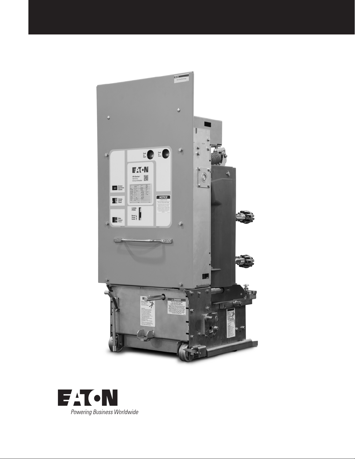
VR-Series+ Replacement Circuit Breaker
50DHP-VR+ 250 1200A Shown

DHP-VR
+
VR-Ser ies+ Replacement Circuit Breaker
DISCLAIMER OF WARRANTIES AND LIMITATION OF LIABILITY
The information, recommendations, descriptions and safety notations in this document are based on Eaton’s experience and judgment and
may not cover all contingencies. If further information is required, an Eaton sales office should be consulted. Sale of the product shown in
this literature is subject to the terms and conditions outlined in appropriate Eaton selling policies or other contractual agreement between
Eaton and the purchaser.
THERE ARE NO UNDERSTANDINGS, AGREEMENTS, WARRANTIES, EXPRESSED OR IMPLIED, INCLUDING WARRANTIES OF FITNESS
FOR A PARTICULAR PURPOSE OR MERCHANTABILITY, OTHER THAN THOSE SPECIFICALLY SET OUT IN ANY EXISTING CONTRACT
BETWEEN THE PARTIES. ANY SUCH CONTRACT STATES THE ENTIRE OBLIGATION OF EATON. THE CONTENTS OF THIS DOCUMENT
SHALL NOT BECOME PART OF OR MODIFY ANY CONTRACT BETWEEN THE PARTIES.
In no event will Eaton be responsible to the purchaser or user in contract, in tort (including negligence), strict liability or other-wise for any
special, indirect, incidental or consequential damage or loss whatsoever, including but not limited to damage or loss of use of equipment,
plant or power system, cost of capital, loss of power, additional expenses in the use of existing power facilities, or claims against the
purchaser or user by its customers resulting from the use of the information, recommendations and descriptions contained herein. The
information contained in this manual is subject to change without notice.
m DANGER
IMPROPERLY INSTALLING OR MAINTAINING THESE PRODUCTS MAY
CAUSE THE EQUIPMENT TO FAIL, RESULTING IN DEATH, SEVERE
PERSONAL INJURY, EQUIPMENT DAMAGE AND/OR IMPROPER
OPERATION.
READ AND UNDERSTAND THESE INSTRUCTIONS BEFORE ATTEMPTING
ANY UNPACKING, ASSEMBLY, OPERATION OR MAINTENANCE OF THE
CIRCUIT BREAKERS.
INSTALLATION OR MAINTENANCE SHOULD BE ATTEMPTED ONLY
BY QUALIFIED PERSONNEL. THIS INSTRUCTION BOOKLET SHOULD
NOT BE CONSIDERED ALL INCLUSIVE REGARDING INSTALLATION OR
MAINTENANCE PROCEDURES. IF FURTHER INFORMATION IS REQUIRED,
YOU SHOULD CONSULT EATON’S ELECTRICAL SERVICES & SYSTEMS.
THE CIRCUIT BREAKERS DESCRIBED IN THIS BOOK ARE DESIGNED AND
TESTED TO OPERATE WITHIN THEIR NAMEPLATE RATINGS. OPERATION
OUTSIDE OF THESE RATINGS MAY CAUSE THE EQUIPMENT TO FAIL,
RESULTING IN DEATH, SEVERE PERSONAL INJURY, EQUIPMENT DAMAGE
AND/OR IMPROPER OPERATION.
ALL SAFETY CODES, SAFETY STANDARDS AND/OR REGULATIONS AS
THEY MAY BE APPLIED TO THIS TYPE OF EQUIPMENT MUST BE STRICTLY
ADHERED TO.
THESE VACUUM REPLACEMENT CIRCUIT BREAKERS ARE DESIGNED TO
BE INSTALLED PURSUANT TO THE AMERICAN NATIONAL STANDARDS
INSTITUTE (ANSI). SERIOUS INJURY, INCLUDING DEATH, SEVERE
PERSONAL INJURY, EQUIPMENT DAMAGE AND/OR IMPROPER
OPERATION.
This product was manufactured by Eaton at the Power Breaker
Center (PBC): 310 Maxwell Avenue, Greenwood, SC 29646.
All possible contingencies which may arise during installation,
operation or maintenance, and all details and variations of this
equipment do not purport to be covered by these instructions. If
further information is desired by purchaser regarding his particular
installation, operation or maintenance of particular equipment,
contact an Eaton representative.
ii
Instruction Book IB182917EN September 2018 www.eaton.com

Table of Contents
DISCLAIMER OF WARRANTIES AND LIMITATION OF LIABILIT Y ii
SECTION 1: INTRODUCTION 4
1.1 VISUAL INSTRUCTION BOOKLET ESSENTIALS 4
1.2 QUICK RESPONSE CODE 4
1.3 AVAILABLE DHP-VR+ CIRCUIT BRE AKERS 4
SECT ION 2: SAFE PRACTICES 8
SECT ION 3: RECEIVING, HANDLING, AND STORAGE 9
3.1 RECEIVING 9
3.2 HANDLING 10
3.3 STORAGE 10
3.4 APPROXIMATE WEIGHT BY TYPE 10
SECT ION 4: DESCRIPTION AND OPERATION 15
4.1 VACUUM INTERRUPTER 15
4.1.1 VACUUM INTERRUPTER ASSEMBLY 15
4.1.2 CONTACT EROSION INDICATOR 15
4.1.3 CONTACT WIPE AND STROKE 16
4.2 LINE AND LOAD CONDUCTOR ASSEMBLIES 16
4.3 STORED ENERGY MECHANISM 16
4.3.1 CLOSING SPRING CHARGING 16
4.3.2 CLOSING OPERATION 16
4.3.3 TRIPPING OPERATION 17
4.3.4 TRIP-FREE OPERATION 17
4.4 CONTROL SCHEMES 17
4.4.1 TIMING 17
4.5 SECONDARY DISCONNECT CONTACT BLOCK 17
4.6 INTERLOCKS 19
4.6.1 RACKING-IN INTERLOCK 19
4.6.2 CIRCUIT BREAKER - CODE PLATE 19
4.6.3 ANTI-CLOSE INTERLOCK 19
4.6.4 FLOOR TRIPPING AND CLOSING SPRING RELEASE INTERLOCKS 19
4.6.5 RAIL LATCH 19
4.7 MISCELLANEOUS ITEMS 20
4.7.1 GROUNDING CONTACT 20
4.7.2 MOC AND TOC OPER ATIONS 20
4.7.3 OPERATIONS COUNTER 20
4.7.4 RACKING DEVICE 20
DHP-VR
VR-Ser ies+ Replacement Circuit Breaker
SECT ION 5: INSPECTION & INSTALLATION 27
5.1 EXAMINATION FOR DAMAGE 27
5.1.1 NAMEPLATE VERIFICATION 27
5.2 SURE CLO SE MECHANISM ADJUSTMENT 27
5.3 MECHANISM OPERATED CELL (MOC) SWITCH PANTOGR APH
ADJUSTMENT 28
5.4 MANUAL OPERATION CHECK 28
5.5 VACUUM INTERRUPTER INTEGRITY 28
5.6 INSULATION 28
5.7 CONTACT EROSION AND WIPE 28
5.8 PRIMARY CIRCUIT RESISTANCE 28
5.9 SNUBBER ADJUSTMENT 28
5.10 ELECTRICAL OPERATIONS CHECK 28
5.11 RACKING CIRCUIT BREAKER INTO CIRCUIT BREAKER COMPARTMENT 30
5.12 REMOVING CIRCUIT BREAKER FROM CIRCUIT BREAKER COMPARTMENT 30
SECT ION 6: INSPECTION & MAINTENANCE 31
6.1 INSPECTION FREQUENCY 31
6.2 INSPECTION AND MAINTENANCE PROCEDURES 31
6.3 VACUUM INTERRUPTER INTEGRITY TEST 32
6.4 CONTACT EROSION AND WIPE 32
6.5 INSULATION 33
6.6 INSULATION INTEGRIT Y CHECK 33
6.7 PRIMARY CIRCUIT RESISTANCE CHECK 33
6.8 VR-SERIES+ CIRCUIT BREAKER ELEMENT MECHANISM CHECK 33
6.8.1 CLOSURE™ TEST (50DHP-VR+ Models) 33
6.8.2 CLOSURE™ TEST (75/150DHP-VR+ Models) 37
6.9 MAINTENANCE RECOMMENDATION 40
SECT ION 7: REPL ACEMENT PARTS 42
7.1 GENERAL 42
7.2 ORDERING INSTRUCTIONS 42
+
Instruction Book IB182917EN September 2018 www.eaton.com
iii

DHP-VR
+
VR-Ser ies+ Replacement Circuit Breaker
SECTION 1: INTRODUCTION
This instruction booklet provides information on receiving and
handling, storage, installation, operation and maintenance of the
DHP VR-Series
Replacement circuit breakers (also referred to as VR-Series
designed to be used in existing Westinghouse type DHP metal-clad
switchgear. The VR-Series
and mechanical performance as compared to the design ratings
of the original circuit breaker. VR-Series
reliable control, protection and performance, with ease of handling
and maintenance. Like ratings of the VR-Series
interchangeable with each other.
The VR-Series
• 10-year or 10,000 operation scheduled maintenance intervals.
When applied in “usual service conditions” as defined by IEEE
C37.04-1999, the VR-Series
maintenance only once every ten years or ten thousand
operations, which ever comes first.
ote:N See Inspection & Maintenance section in this booklet for details.
• Increased mechanical endurance. Circuit breakers in repetitive
duty applications offer 50% more operations over conventional
vacuum circuit breaker elements before parts replacement may
be needed.
• Increased short circuit capability. The VR-Series+ circuit breaker
short circuit capability can be increased to 41 kA, provided a bus
bracing study is performed and the switchgear is adequately
braced to meet the requirements per IEEE C37.59.
Use this instruction bulletin in conjunction with the technical
information provided with the original equipment order which
includes electrical control schematic and wiring diagrams, outline
diagrams, installations plans, and procedures for installation and
maintenance of accessory items.
Satisfactory performance is dependent on proper application, correct
installation, and adequate maintenance. It is very important that
this installation and maintenance instruction booklet be read and
followed closely to achieve optimum performance and a long useful
circuit breaker life in its application.
1.1 VISUAL INSTRUCTION BOOKLET ESSENTIALS
Eaton provides additional documentation designed to enhance the
technical information provided in this instruction booklet for the
VR-Series
(VIBE) is a digital supplemental booklet featuring user interactive
content and informative videos intended to assist with the
maintenance of the VR-Series
available for immediate download at www.eaton.com/VR-Series.
+
vacuum replacement circuit breaker. The Vacuum
+
circuit breakers provide superior electrical
+
Circuit breakers provide
+
circuit breakers are
+
circuit breaker element offers:
+
circuit breaker element requires
+
circuit breakers. The Visual Instruction Booklet Essentials
+
circuit breaker. The VIBE document is
+
) are
Figure 1.1. Quick Response Code
VR-Series+ QR Code
1.2 QUICK RESPONSE CODE
VR-Series+ circuit breakers have a quick response code (QR Code)
on the escutcheon of the circuit breaker front cover. This QR Code is
a matrix barcode that provides direct access to download VR-Series
specific documentation, such as product instruction booklets and the
VIBE documentation. See Figure 1.1 for the featured VR-Series
Code.
ote:N A smart phone with an adequate QR Code Scanner application must be
used. Downloading content may incur data charges from the mobile service
provider.
+
QR
+
m WARNING
SATISFACTORY PERFORMANCE OF THESE CIRCUIT BREAKERS IS
CONTINGENT UPON PROPER APPLICATION, CORRECT INSTALLATION
AND ADEQUATE MAINTENANCE. THIS INSTRUCTION BOOKLET MUST
BE CAREFULLY READ AND FOLLOWED IN ORDER TO OBTAIN OPTIMUM
PERFORMANCE FOR LONG USEFUL LIFE OF THE CIRCUIT BREAKERS. IT IS
FURTHER RECOMMENDED THAT THE INSTALLATION BE PERFORMED BY
AN EATON TRAINED ENGINEER OR TECHNICIAN.
+
VR-SERIES
THEY ARE MAXIMUM RATED DEVICES. THEREFORE, THEY SHOULD NOT
UNDER ANY CIRCUMSTANCE BE APPLIED OUTSIDE THEIR NAMEPLATE
RATINGS.
ALL POSSIBLE CONTINGENCIES WHICH MIGHT ARISE DURING
INSTALLATION, OPERATION, OR MAINTENANCE, AND ALL DETAILS
AND VARIATIONS OF THIS EQUIPMENT ARE NOT COVERED BY THESE
INSTRUCTIONS. IF FURTHER INFORMATION IS DESIRED BY THE
PURCHASER REGARDING A PARTICULAR INSTALLATION, OPERATION, OR
MAINTENANCE OF THIS EQUIPMENT, THE LOCAL EATON REPRESENTATIVE
SHOULD BE CONTACTED.
1.3 AVAILABLE DHP-VR+ CIRCUIT BREAKERS
Refer to Table 1.
CIRCUIT BREAKERS ARE PROTECTIVE DEVICES, AS SUCH,
4
Instruction Book IB182917EN September 2018 www.eaton.com

Table 1. DHP-VR+ Availability and Interchangeability
DHP-VR
VR-Ser ies+ Replacement Circuit Breaker
+
Nominal
3-Phase
Maximum
+
Existing
DHP
Circuit
Breaker Type
50DHP75 50DHP-VR
50DHP75 50DHP-VR
50DHEP250 50DHEP-VR
50DHP250 50DHP-VR
H50DHP250
50DHP250 50DHP-VR
75DHP500 75DHP-VR
75DVP500 75DVP-VR
150DHP500 150DHP-VR
150DVP500 150DVP-VR
150DVP500 150DVP-VR
H150DHP500 150DHP-VR
150DHP500 150DHP-VR
150DHP750 150DHP-VR
150DVP750 150DVP-VR
H150DHP750 150DHP-VR
150DHP750C 150DHP-VR
H150DHP750C 150DHP-VR
150DHP500/750 150DHP-VR
a
All circuit breakers have a 3 second short-time and 3-cycle interrupting ratings.
b
Non-standard rating.
c
Requires bus bracing study and additional switchgear bracing.
DHP-VR
Circuit Breaker
a
Type
+
75 4.76 75 1200 1.36 19 60 8.8 12 19 / 32
+
75U
+
250 4.76 250 1200 / 2000 1.24 19 60 29 36 58 / 97
+
250 4.76 250 1200 / 2000 1.24 19 60 29 36 58 / 97
+
50DHP-VR
250H
+
bc
41
+
500 8.25 500 1200 / 2000 1.25 36 95 33 41 66 / 111
+
500 8.25 500 1200 / 2000 1.25 36 95 33 41 66 / 111
+
500 15 500 1200 / 2000 1.30 36 95 18 23 37 / 62
+
500 15 500 1200 / 2000 1.30 36 95 18 23 37 / 62
+
500U
+
500H 15 500 1200 / 2000 1.30 36 95 18 23 58 / 97
+
500U
+
750 15 750 1200 / 2000 1.30 36 95 28 36 58 / 97
+
750 15 750 1200 / 2000 1.30 36 95 28 36 58 / 97
+
750H 15 750 1200 / 2000 1.30 36 95 28 36 77 / 130
+
750C 15 750 1200 / 2000 1.30 36 95 28 36 58 / 97
+
750CH 15 750 1200 / 2000 1.30 36 95 28 36 77 / 130
+
41
Voltage
kV MVA Amps K
c
4.76 75 1200 1.24 19 60 29 36 58 / 97
4.76 250 1200 / 2000 1.24 19 60 29 36 78 / 132
4.76 N/A 1200 / 2000 1.00 19 60 41 41 78 / 132
c
15 750 1200 / 2000 1.30 36 95 28 36 58 / 97
c
15 750 1200 / 2000 1.30 36 95 28 36 58 / 97
bc
15 N/A 1200 / 2000 1.00 36 95 41 41 77 / 130
MVA
Class
Existing Circuit
Breaker Rated
Continuous
Current at 60 Hz
Rated
Voltage
Factor
Rated Withstand
ANSI Test Voltage
Low Freq.
kV RMS
Impulse
kV PeakIkA RMS
Rated
Short-Circuit
Closing and
Maximum Sym.
Interrupting
Capability
KI
kA RMS kA RMS / Peak
Latching /
Momentary
Capabilities
Instruction Book IB182917EN September 2018 www.eaton.com
5
DHP-VR
+
VR-Ser ies+ Replacement Circuit Breaker
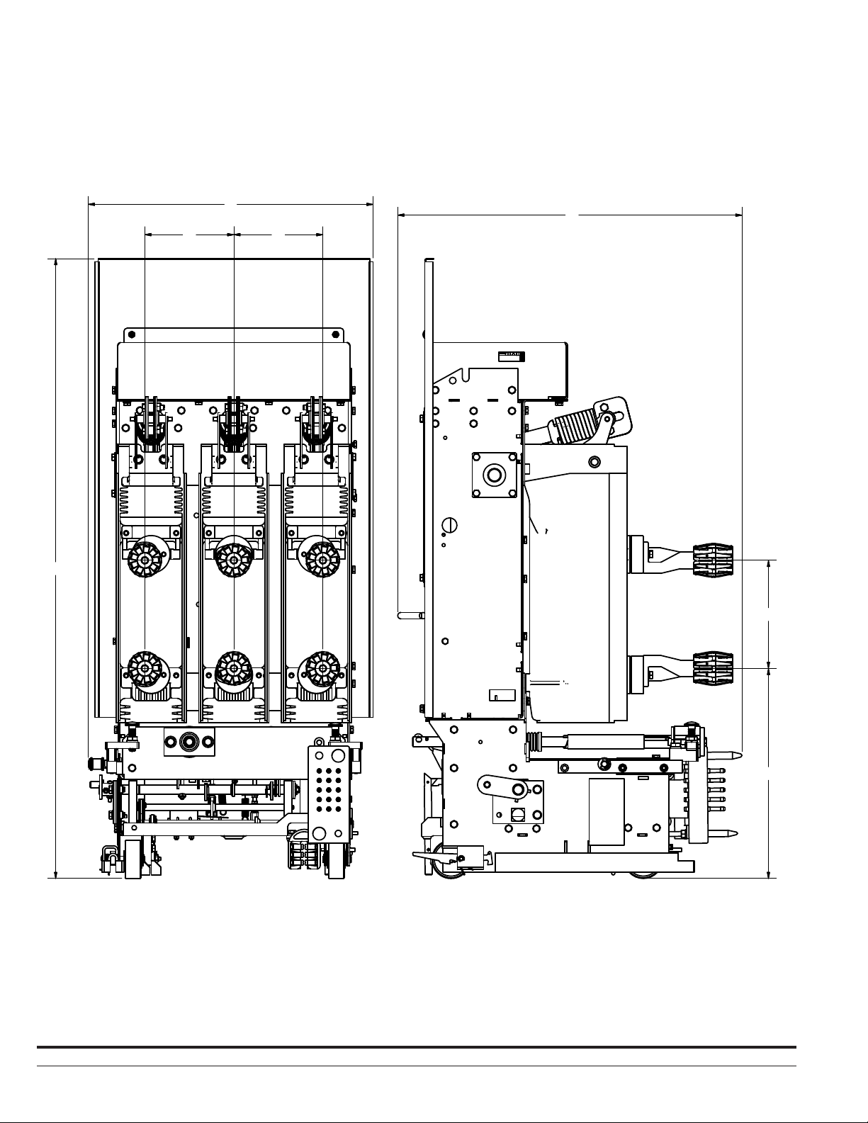
B
D
C C
A
E
Table 2. Available DHP-VR+ Dimensions
Existing Circuit
Breaker Rated
Continuous
Current at 60 Hz
Circuit Breaker Type
50DHP-VR+ 1200 / 2000 48.75 22.39 7.00 27.40 8.50 16.52
6
(Amps) A B C D E F
Instruction Book IB182917EN September 2018 www.eaton.com
F
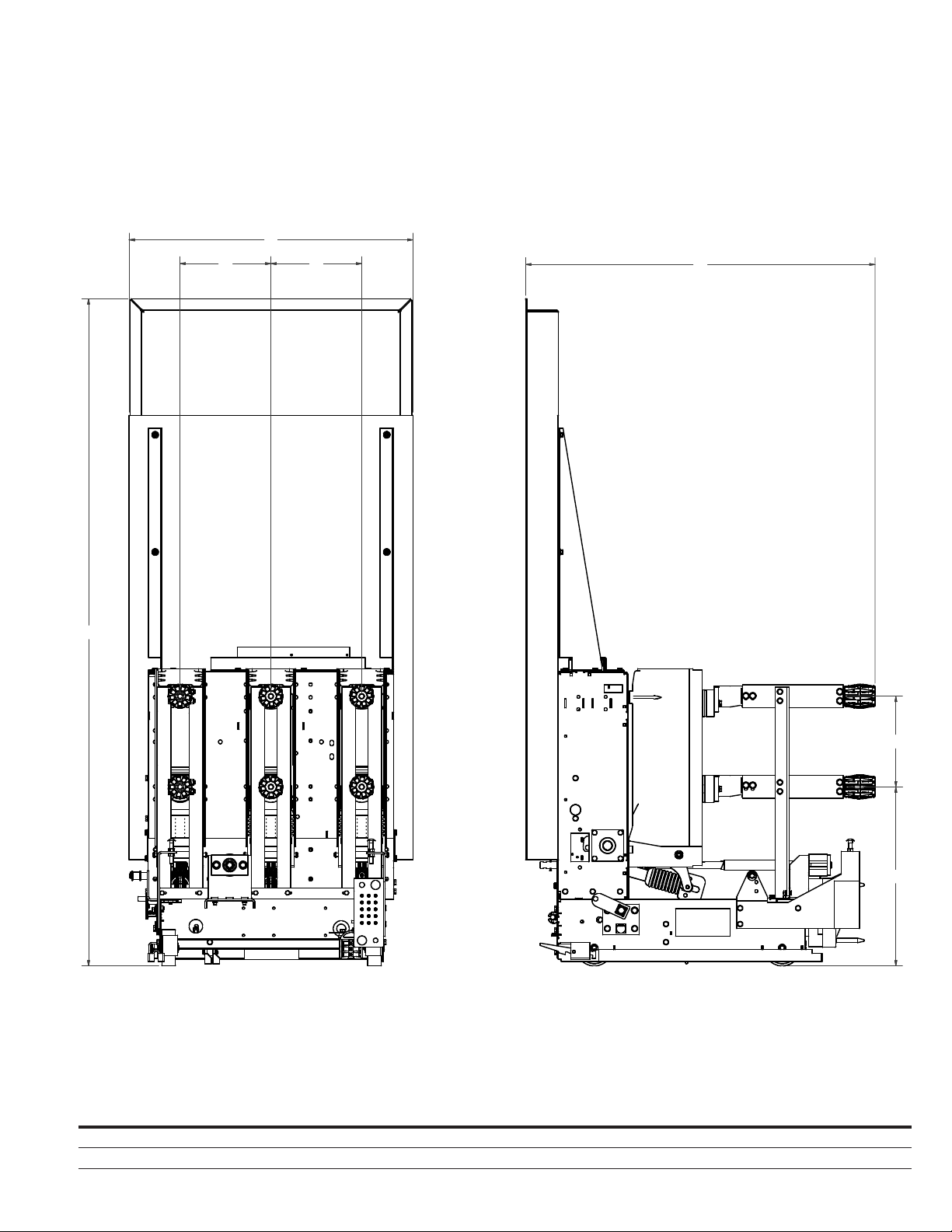
B
C C
DHP-VR
VR-Ser ies+ Replacement Circuit Breaker
D
+
A
Table 3. Available DHP-VR+ Dimensions
Existing Circuit
Breaker Rated
Continuous
Current at 60 Hz
Circuit Breaker Type
75/150DHP/DVP-VR
150DHP-VR
+
+
750C 1200 / 2000 73.60 31.01 10.00 38.46 10.00 19.75
500/750 1200 / 2000 60.71 31.25 10.00 34.97 10.00 19.75
(Amps) A B C D E F
E
F
Instruction Book IB182917EN September 2018 www.eaton.com
7

DHP-VR
+
VR-Ser ies+ Replacement Circuit Breaker
SECTION 2: SAFE PRACTICES
VR-Series+ circuit breakers are equipped with high speed, high
energy operating mechanisms. They are designed with several builtin interlocks and safety features to provide safe and proper operating
sequences.
m DANGER
TO PROTECT THE PERSONNEL ASSOCIATED WITH INSTALLATION,
OPERATION, AND MAINTENANCE OF THESE CIRCUIT BREAKERS, THE
FOLLOWING PRACTICES MUST BE FOLLOWED:
•
Only qualified persons, as defined in the National Electrical
Safety Code, who are familiar with the installation and
maintenance of medium voltage circuits and equipment,
should be permitted to work on these circuit breakers.
•
Read these instructions carefully before attempting any
installation, operation or maintenance of these circuit
breakers.
•
Always remove the circuit breaker from the enclosure before
performing any maintenance. Failure to do so could result in
electrical shock leading equipment failure, resulting in death,
severe personal injury, equipment damage and/or improper
operation.
•
Do not work on a circuit breaker with the secondary test
coupler engaged. Failure to disconnect the test coupler could
result in an electrical shock leading to death, severe personal
injury, equipment damage and/or improper operation.
•
Do not work on a closed circuit breaker or a circuit breaker
with closing springs charged. The closing spring should be
discharged and the main contacts open before working on
the circuit breaker. Failure to do so could result in cutting or
crushing injuries.
•
Do not use a circuit breaker by itself as the sole means of
isolating a high voltage circuit. Remove the circuit breaker
to the ‘Disconnect’ position and follow all lockout and
tagging rules of the National Electrical Code and any and all
applicable codes, regulations and work rules.
•
Do not leave the circuit breaker in an intermediate position
in the circuit breaker compartment. Always have the circuit
breaker either in the ‘Test’ or ‘Connect’ position. Failure to do
so could result in a flash over causing the equipment to fail,
resulting in death, severe personal injury, equipment damage
and/or improper operation.
•
Always remove the maintenance tool from the circuit breaker
after charging the closing springs.
•
Circuit breakers are equipped with safety interlocks. Do not
defeat them. This may result in equipment failure, resulting
in death, severe personal injury, equipment damage and/or
improper operation.
8
Instruction Book IB182917EN September 2018 www.eaton.com

DHP-VR
VR-Ser ies+ Replacement Circuit Breaker
+
SECTION 3: RECEIVING, HANDLING, AND
STORAGE
VR-Series+ circuit breakers are subjected to complete factory
production tests and inspection before being packed. They are
shipped in packages designed to provide maximum protection to the
equipment during shipment and storage and at the same time to
provide convenient handling. Accessories such as the maintenance
tool, code plate, (if applicable) etc. are shipped with the circuit
breaker.
3.1 RECEIVING
Until the circuit breaker is ready to be delivered to the switchgear
site for installation, DO NOT remove it from the shipping crate. If the
circuit breaker is to be placed in storage, maximum protection can
be obtained by keeping it in its crate.
Upon receipt of the equipment, inspect the crates for any signs of
damage or rough handling. Open the crates carefully to avoid any
damage to the contents. Use a nail puller rather than a crow bar
when required.
When opening the crates, be careful that any loose items or
hardware are not discarded with the packing material. Check the
contents of each package against the packing list.
Examine the circuit breaker for any signs of shipping damage
such as broken, missing or loose hardware, damaged or deformed
insulation and other components. If damaged or loss is detected,
file claims immediately with the carrier and notify an Eaton
representative.
Figure 3.1.a. Maintenance Tool
Figure 3.1.b. Rotary Racking Handle
Figure 3.1.c. Turning Dolly
Tools and Accessories
Maintenance Tool (Style# 94C9506G01): This tool is used to
manually charge the closing springs. One maintenance tool is
provided with each vacuum replacement circuit breaker.
Racking Handle (Style# 509A931G01): Optional racking handle
used to drive the racking mechanism which moves the circuit
breaker into and out of the circuit breaker compartment. The OEM
racking handle will interface with the VR-Series
breaker racking mechanism and is therefore not provided as part of
the vacuum replacement circuit breaker.
Lifting Strap (Style# 94B1194G01): Optional item recommended
for lifting the DHP-VR
Turning Dolly (Style# 94A9502G02): Optional item used to
help maneuver circuit breaker when out of the circuit breaker
compartment.
+
circuit breaker.
+
replacement circuit
Instruction Book IB182917EN September 2018 www.eaton.com
9
DHP-VR
+
VR-Ser ies+ Replacement Circuit Breaker
3.2 HANDLING
m WARNING
DO NOT USE ANY LIFTING DEVICE AS A PLATFORM FOR PERFORMING
MAINTENANCE, REPAIR OR ADJUSTMENT OF THE CIRCUIT BREAKER OR
FOR OPENING, CLOSING THE CONTACTS OR CHARGING THE SPRINGS.
THE CIRCUIT BREAKER MAY SLIP OR FALL CAUSING SEVERE PERSONAL
INJURY. ALWAYS PERFORM MAINTENANCE, REPAIR AND ADJUSTMENTS
ON A WORKBENCH CAPABLE OF SUPPORTING THE CIRCUIT BREAKER
TYPE.
+
VR-Series
handled either by use of an overhead lifting device or by a fork lift
truck. If containers must be skidded for any distance, it is preferable
to use roller conveyors or individual pipe rollers.
Once a circuit breaker has been inspected for shipping damage, it
is best to return it to its original shipping crate until it is ready to be
installed in the metal-clad switchgear.
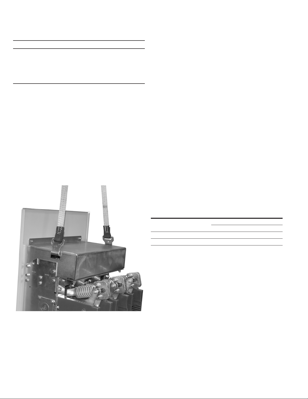
When the circuit breaker is ready for installation, a lifting harness in
conjunction with an overhead lift or portable floor lift can be used
to move the circuit breaker. If the circuit breaker is to be lifted,
position the lifting device over the circuit breaker and insert the
lifting harness hooks into the circuit breaker side lifting points and
secure (lifting straps should have at least a 1000lbs lift capacity). Be
sure the hooks are firmly attached before lifting the circuit breaker.
Stand a safe distance away from the circuit breaker while lifting and
moving.
Figure 3.2. Lifting the DHP-VR
circuit breaker shipping containers are designed to be
+
3.3 STORAGE
If the circuit breaker is to be placed in storage, maximum protection
can be obtained by keeping it in the original shipping crate. Confirm
that the circuit breaker is free from shipping damage and is in
satisfactory operating condition before placing it in to storage.
The circuit breaker is shipped with its contacts open and closing
springs discharged. The indicators on the front cover should confirm
this. Insert the end of the maintenance tool into the manual charge
socket opening and charge the closing springs by moving the
handle up and down the full range of motion. When charging is
complete the ratchet will no longer advance and the spring charged
/ discharged indicator displays ‘Charged’. (Figure Set 3.3). Remove
the maintenance tool. Push the “manual close” operator. The circuit
breaker will close as shown by the circuit breaker contacts ‘Closed’
indicator. Push the “manual trip” operator. The circuit breaker will
trip as shown by the circuit breaker contacts ‘Open’ indicator. After
completing this initial check, leave the closing springs ‘Discharged’
and circuit breaker contacts ‘Open’.
Outdoor storage is NOT recommended. If unavoidable, the outdoor
location must be well drained and a temporary shelter from sun,
rain, snow, corrosive fumes, dust, dirt, falling objects, excessive
moisture, etc. must be provided. Containers should be arranged
to permit free circulation of air on all sides and temporary heaters
should be used to minimize condensation. Moisture can cause
rusting of metal parts and deterioration of high voltage insulation.
A heat level of approximately 400 watts for each 100 cubic feet
of volume is recommended with the heaters distributed uniformly
throughout the structure near the floor.
Indoor storage should be in a building with sufficient heat and
circulation to prevent condensation. If the building is not heated, the
same general rule for heat as for outdoor storage should be applied.
3.4 APPROXIMATE WEIGHT BY TYPE
Table 4. Approximate Weight by Type
Type Amperes LBs
+
50DHP-VR
75/150DHP-VR
1200 475
2000 490
+
1200 535
2000 595
10
Instruction Book IB182917EN September 2018 www.eaton.com
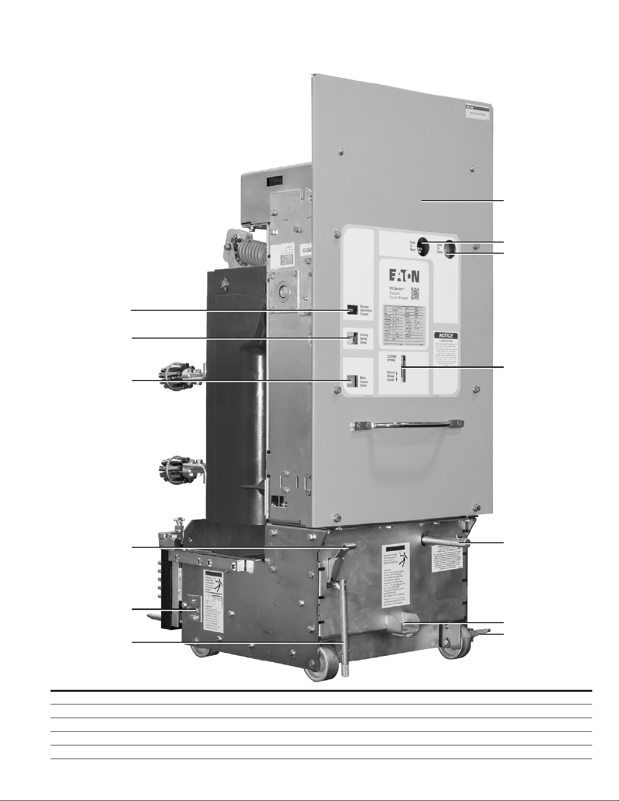
Figure 3.3.a. Front External View of DHP-VR+ (50DHP-VR+ 250 1200A Shown)
1
DHP-VR
VR-Ser ies+ Replacement Circuit Breaker
7
8
9
+
2
10
3
4
11
5
12
13
6
Front External View
1 Operations Counter 6 Secondary Disconnect Contact Operating Rod 11 Racking Shaft
2 Spring Charged / Discharged Indicator 7 Front Cover 12 Turning Dolly Bracket
3 Circuit Breaker Contact Status Indicator 8 Push To Open Operator 13 Rail Latch
4 Secondary Disconnect Contact Engaging Handle 9 Push To Close Operator
5 Code Plate 10 Manual Charge Socket
Instruction Book IB182917EN September 2018 www.eaton.com
11
DHP-VR
+
VR-Ser ies+ Replacement Circuit Breaker
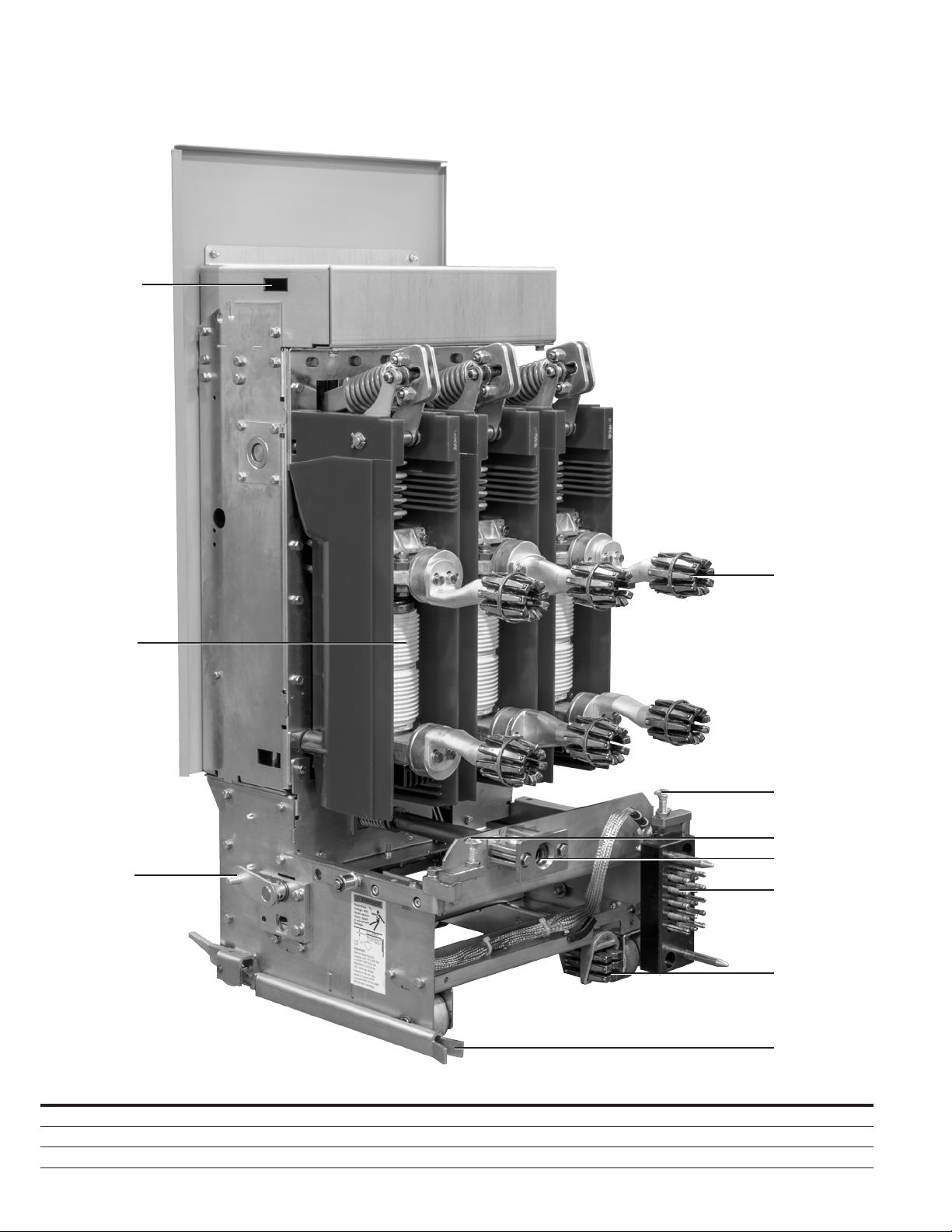
Figure 3.3.b. Rear External View of DHP-VR+ (50DHP-VR+ 250 1200A Shown)
1
4
2
5
5
6
3
7
8
Rear External View
1 Lifting Point 4 Primary Disconnect Contact 7 Secondary Disconnect Contact Block
2 Vacuum Interrupter 5 Snubber Bolts 8 Ground Contact
3 MOC Switch Operating Mechanism 6 Racking Nut Housing 9 Guide Channel
12
Instruction Book IB182917EN September 2018 www.eaton.com
9
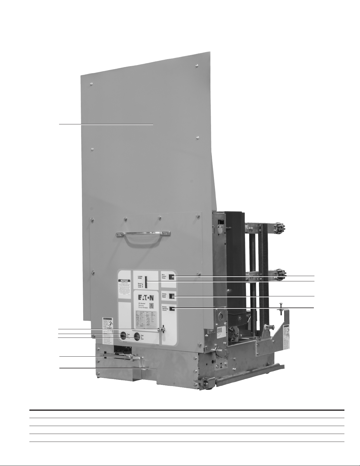
Figure 3.3.c. Front External View of DHP-VR+ (150DHP-VR+ 500 1200A Shown)
1
DHP-VR
VR-Ser ies+ Replacement Circuit Breaker
+
2
3
4
5
6
Front External View
1 Front Cover 5 Secondary Disconnect Contact Operating Rod 9 Spring Charged / Discharged Indicator
2 Racking Shaft 6 Turning Dolly Bracket 10 Operations Counter
3 Push to Open Operator 7 Circuit Breaker Contact Status Indicator
4 Push to Close Operator 8 Manual Charge Socket
7
8
9
10
Instruction Book IB182917EN September 2018 www.eaton.com
13
 Loading...