

Eaton PowerXL DG1 Series, VFD Series, DG1-357D6FB-C21C Communications Manual
PowerXL DG1 Series VFD
Effective September 2016
Supersedes May 2014
Communication manual

DISCLAIMER OF WARRANTIES AND LIMITATION OF LIABILITY
The information, recommendations, descriptions, and safety notations in this document are based on Eaton’s experience and
judgment and may not cover all contingencies. If further information is required, an Eaton sales office should be consulted.
Sale of the product shown in this literature is subject to the terms and conditions outlined in appropriate Eaton selling
policies or other contractual agreement between Eaton and the purchaser.
THERE ARE NO UNDERSTANDINGS, AGREEMENTS, WARRANTIES, EXPRESSED OR IMPLIED, INCLUDING WARRANTIES
OF FITNESS FOR A PARTICULAR PURPOSE OR MERCHANTABILITY, OTHER THAN THOSE SPECIFICALLY SET OUT IN ANY
EXISTING CONTRACT BETWEEN THE PARTIES. ANY SUCH CONTRACT STATES THE ENTIRE OBLIGATION OF EATON. THE
CONTENTS OF THIS DOCUMENT SHALL NOT BECOME PART OF OR MODIFY ANY CONTRACT BETWEEN THE PARTIES.
In no event will Eaton be responsible to the purchaser or user in contract, in tort (including negligence), strict liability, or
otherwise for any special, indirect, incidental, or consequential damage or loss whatsoever, including but not limited to
damage or loss of use of equipment, plant or power system, cost of capital, loss of power, additional expenses in the use of
existing power facilities, or claims against the purchaser or user by its customers resulting from the use of the information,
recommendations, and descriptions contained herein. The information contained in this manual is subject to change
withoutnotice.
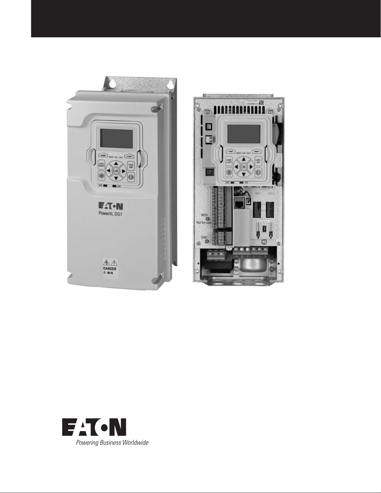
Cover Photo: Eaton PowerXL® HVAC Drives
ii POWERXL DG1 SERIES VFD MN040010EN—September 2016 www.eaton.com

Support services
Support services
The goal of Eaton is to ensure your greatest possible
satisfaction with the operation of our products. We
are dedicated to providing fast, friendly, and accurate
assistance. That is why we offer you so many ways to get
the support you need. Whether it is by phone, fax, or email,
you can access Eaton’s support information 24 hours a day,
seven days a week.
Our wide range of services is listed below.
You should contact your local distributor for product pricing,
availability, ordering, expediting, and repairs.
Website
Use the Eaton Website to find product information. You
can also find information on local distributors or Eaton’s
salesoffices.
Website address
www.eaton.com/drives
PowerXL DG1 Series VFD
EatonCare customer support center
Call the EatonCare Support Center if you need assistance
with placing an order, stock availability or proof of shipment,
expediting an existing order, emergency shipments, product
price information, returns other than warranty returns, and
information on local distributors or sales offices.
Voice: 877-ETN-CARE (386-2273) (8:00 a.m.–6:00 p.m. EST)
After-Hours Emergency: 800-543-7038
(6:00 p.m.–8:00 a.m. EST)
Drives technical resource center
Voice: 877-ETN-CARE (386-2273) option 2, option 6
(8:00 a.m.–5:00 p.m. Central Time U.S. [UTC –6])
email: TRCDrives@Eaton.com
For customers in europe, contact
Phone: +49 (0) 228 6 02-3640
Hotline: +49 (0) 180 5 223822
email: AfterSalesEGBonn@Eaton.com
www.eaton.com/moeller/aftersales
POWERXL DG1 SERIES VFD MN040010EN—September 2016 www.eaton.com
iii

PowerXL DG1 Series VFD
Contents
SAFETY
Before commencing the installation . . . . . . . . . . . . . . . . . . . . . . . . . . . . . . . . . ..xiii
Definitions and symbols . . . . . . . . . . . . . . . . . . . . . . . . . . . . . . . . . . . . . . . . . . ..xiv
Hazardous high voltage . . . . . . . . . . . . . . . . . . . . . . . . . . . . . . . . . . . . . . . . . . . ..xiv
Warnings and cautions . . . . . . . . . . . . . . . . . . . . . . . . . . . . . . . . . . . . . . . . . . . ..xiv
Motor and equipment safety ...........................................xvii
POWERXL SERIES OVERVIEW
How to use this manual . . . . . . . . . . . . . . . . . . . . . . . . . . . . . . . . . . . . . . . . . . ....1
Receiving and inspection . . . . . . . . . . . . . . . . . . . . . . . . . . . . . . . . . . . . . . . . . . ...1
Real time clock battery activation . . . . . . . . . . . . . . . . . . . . . . . . . . . . . . . . . . .....1
Rating label . . . . . . . . . . . . . . . . . . . . . . . . . . . . . . . . . . . . . . . . . . . . . . . . . . . . ....2
Carton labels (U.S. and Europe) . . . . . . . . . . . . . . . . . . . . . . . . . . . . . . . . . . . . .....2
General information . . . . . . . . . . . . . . . . . . . . . . . . . . . . . . . . . . . . . . . . . . . . . . ...2
OPTION CARD SLOTS
Installing DG1 option board . . . . . . . . . . . . . . . . . . . . . . . . . . . . . . . . . . . . . . . . ....4
Control wiring . . . . . . . . . . . . . . . . . . . . . . . . . . . . . . . . . . . . . . . . . . . . . . . . . . ....4
EMC directive . . . . . . . . . . . . . . . . . . . . . . . . . . . . . . . . . . . . . . . . . . . . . . . . . . ....5
Control cable grounding . . . . . . . . . . . . . . . . . . . . . . . . . . . . . . . . . . . . . . . . . . ....5
MODBUS RTU ON-BOARD COMMUNICATIONS
Modbus RTU specifications . . . . . . . . . . . . . . . . . . . . . . . . . . . . . . . . . . . . . . . . ...7
Commissioning . . . . . . . . . . . . . . . . . . . . . . . . . . . . . . . . . . . . . . . . . . . . . . . . . ....8
Modbus communication standards . . . . . . . . . . . . . . . . . . . . . . . . . . . . . . . . . . ....9
MODBUS TCP ON-BOARD COMMUNICATIONS
Modbus/TCP specifications . . . . . . . . . . . . . . . . . . . . . . . . . . . . . . . . . . . . . . . . ...17
Hardware specifications . . . . . . . . . . . . . . . . . . . . . . . . . . . . . . . . . . . . . . . . . . ...17
Commissioning . . . . . . . . . . . . . . . . . . . . . . . . . . . . . . . . . . . . . . . . . . . . . . . . . ...19
Modbus communication standards . . . . . . . . . . . . . . . . . . . . . . . . . . . . . . . . . . ...25
ETHERNET/IP ON-BOARD COMMUNICATIONS
EtherNet/IP specifications . . . . . . . . . . . . . . . . . . . . . . . . . . . . . . . . . . . . . . . . . ...31
Hardware specifications . . . . . . . . . . . . . . . . . . . . . . . . . . . . . . . . . . . . . . . . . . ...32
EtherNet/IP overview . . . . . . . . . . . . . . . . . . . . . . . . . . . . . . . . . . . . . . . . . . . . ...34
Commissioning . . . . . . . . . . . . . . . . . . . . . . . . . . . . . . . . . . . . . . . . . . . . . . . . . ...36
PLC programming . . . . . . . . . . . . . . . . . . . . . . . . . . . . . . . . . . . . . . . . . . . . . . . ...40
BACNET MS/TP—ON-BOARD COMMUNICATION
BACnet MS/TP specifications . . . . . . . . . . . . . . . . . . . . . . . . . . . . . . . . . . . . . . ...69
Commissioning . . . . . . . . . . . . . . . . . . . . . . . . . . . . . . . . . . . . . . . . . . . . . . . . . ...72
BACnet overview . . . . . . . . . . . . . . . . . . . . . . . . . . . . . . . . . . . . . . . . . . . . . . . ...74
iv
POWERXL DG1 SERIES VFD MN040010EN—September 2016 www.eaton.com

PROFIBUS-DP EXTERNAL COMMUNICATION CARDS
PROFIBUS specifications . . . . . . . . . . . . . . . . . . . . . . . . . . . . . . . . . . . . . . . . . ...79
Hardware specifications . . . . . . . . . . . . . . . . . . . . . . . . . . . . . . . . . . . . . . . . . . ...80
PROFIBUS cable . . . . . . . . . . . . . . . . . . . . . . . . . . . . . . . . . . . . . . . . . . . . . . . . ...82
Commissioning . . . . . . . . . . . . . . . . . . . . . . . . . . . . . . . . . . . . . . . . . . . . . . . . . ...83
PROFIBUS—PowerXL DG1 . . . . . . . . . . . . . . . . . . . . . . . . . . . . . . . . . . . . . . . . ...85
PROFIBUS overview . . . . . . . . . . . . . . . . . . . . . . . . . . . . . . . . . . . . . . . . . . . . . ...88
CANOPEN EXTERNAL COMMUNICATION CARDS
CANopen technical data ..............................................100
CANopen cable .....................................................10 0
CANopen bus termination .............................................101
Hardware specification ...............................................10 2
Commissioning .....................................................103
CANopen overview ..................................................105
Network management (NMT) ..........................................107
Drive profile state machine ............................................109
Device profile parameters .............................................110
Object directory .....................................................11 6
PowerXL DG1 Series VFD
DEVICENET EXTERNAL COMMUNICATION CARDS
DeviceNet technical data ..............................................122
DeviceNet cabling ...................................................123
Hardware specification ...............................................123
Commissioning .....................................................125
DeviceNet overview .................................................126
APPENDIX A—PARAMETER ID LIST
Parameter descriptions ...............................................147
APPENDIX B—PROCESS IN VALUES
Process in values ....................................................166
APPENDIX C—FAULT CODES
Fault codes ........................................................168
POWERXL DG1 SERIES VFD MN040010EN—September 2016 www.eaton.com
v

PowerXL DG1 Series VFD
List of Figures
Figure 1. RTC battery connection . . . . . . . . . . . . . . . . . . . . . . . . . . . . . . . . . . . . . . . . . 1
Figure 2. Rating label . . . . . . . . . . . . . . . . . . . . . . . . . . . . . . . . . . . . . . . . . . . . . . . . . . 2
Figure 3. DG1 series control board location . . . . . . . . . . . . . . . . . . . . . . . . . . . . . . . . 3
Figure 4. Drive control board layout showing option card slots . . . . . . . . . . . . . . . . . 3
Figure 5. Control cable grounding . . . . . . . . . . . . . . . . . . . . . . . . . . . . . . . . . . . . . . . . . 5
Figure 6. Connection diagram . . . . . . . . . . . . . . . . . . . . . . . . . . . . . . . . . . . . . . . . . . . . 6
Figure 7. Terminal wiring . . . . . . . . . . . . . . . . . . . . . . . . . . . . . . . . . . . . . . . . . . . . . . . . 7
Figure 8. Termination resistor and shielding . . . . . . . . . . . . . . . . . . . . . . . . . . . . . . . . 7
Figure 9. Keypad navigation to rs-485 menu . . . . . . . . . . . . . . . . . . . . . . . . . . . . . . . . 8
Figure 10. The basic structure of a modbus frame . . . . . . . . . . . . . . . . . . . . . . . . . . . . 9
Figure 11. Module and network status . . . . . . . . . . . . . . . . . . . . . . . . . . . . . . . . . . . . . 18
Figure 12. CAT-5e cable . . . . . . . . . . . . . . . . . . . . . . . . . . . . . . . . . . . . . . . . . . . . . . . . 19
Figure 13. Keypad navigation to ethernet comm settings . . . . . . . . . . . . . . . . . . . . . . 19
Figure 14. Static IP mode . . . . . . . . . . . . . . . . . . . . . . . . . . . . . . . . . . . . . . . . . . . . . . . 21
Figure 15. Static IP address . . . . . . . . . . . . . . . . . . . . . . . . . . . . . . . . . . . . . . . . . . . . . 22
Figure 16. Static subnet mask . . . . . . . . . . . . . . . . . . . . . . . . . . . . . . . . . . . . . . . . . . . 23
Figure 17. Static default gateway . . . . . . . . . . . . . . . . . . . . . . . . . . . . . . . . . . . . . . . . . 23
Figure 18. Modbus TCP unit ID . . . . . . . . . . . . . . . . . . . . . . . . . . . . . . . . . . . . . . . . . . . 24
Figure 19. Module and network status . . . . . . . . . . . . . . . . . . . . . . . . . . . . . . . . . . . . . 33
Figure 20. Human to machine user interface . . . . . . . . . . . . . . . . . . . . . . . . . . . . . . . . 34
Figure 21. Machine to machine (industrial environment, fast communication) . . . . . . 34
Figure 22. CAT-5e cable . . . . . . . . . . . . . . . . . . . . . . . . . . . . . . . . . . . . . . . . . . . . . . 35
Figure 23. Static IP mode . . . . . . . . . . . . . . . . . . . . . . . . . . . . . . . . . . . . . . . . . . . . . . 37
Figure 24. Static IP address . . . . . . . . . . . . . . . . . . . . . . . . . . . . . . . . . . . . . . . . . . . . . 38
Figure 25. Static subnet mask . . . . . . . . . . . . . . . . . . . . . . . . . . . . . . . . . . . . . . . . . . . 39
Figure 26. Static default gateway . . . . . . . . . . . . . . . . . . . . . . . . . . . . . . . . . . . . . . . . 39
Figure 27. State transition diagram . . . . . . . . . . . . . . . . . . . . . . . . . . . . . . . . . . . . . . . 59
Figure 28. Principal example diagram . . . . . . . . . . . . . . . . . . . . . . . . . . . . . . . . . . . . . 69
Figure 29. Stripping the cable . . . . . . . . . . . . . . . . . . . . . . . . . . . . . . . . . . . . . . . . . . . 70
Figure 30. RS-485 cable strip (aluminum shield) . . . . . . . . . . . . . . . . . . . . . . . . . . . . . 70
Figure 31. G-Max drive terminals (BACnet) . . . . . . . . . . . . . . . . . . . . . . . . . . . . . . . . . . 70
Figure 32. RS-485 ground . . . . . . . . . . . . . . . . . . . . . . . . . . . . . . . . . . . . . . . . . . . . . . 70
Figure 33. RS-485 bus termination setup . . . . . . . . . . . . . . . . . . . . . . . . . . . . . . . . . . . 71
Figure 34. BACnet bus termination . . . . . . . . . . . . . . . . . . . . . . . . . . . . . . . . . . . . . . . . 71
Figure 35. BACnet parameter navigation . . . . . . . . . . . . . . . . . . . . . . . . . . . . . . . . . . . . 72
Figure 36. Com1 PROFIBUS card layout . . . . . . . . . . . . . . . . . . . . . . . . . . . . . . . . . . . 80
Figure 37. Com1 PROFIBUS DB9 adapter . . . . . . . . . . . . . . . . . . . . . . . . . . . . . . . . . . . 82
Figure 38. PROFIBUS parameter menu . . . . . . . . . . . . . . . . . . . . . . . . . . . . . . . . . . . . . 83
Figure 39. PROFIdrive . . . . . . . . . . . . . . . . . . . . . . . . . . . . . . . . . . . . . . . . . . . . . . . . . 88
Figure 40. Application class . . . . . . . . . . . . . . . . . . . . . . . . . . . . . . . . . . . . . . . . . . . . . 89
Figure 41. General state diagram . . . . . . . . . . . . . . . . . . . . . . . . . . . . . . . . . . . . . . . . 95
vi
POWERXL DG1 SERIES VFD MN040010EN—September 2016 www.eaton.com

Figure 42. CANopen bus termination ....................................101
Figure 43. CANopen hardware .........................................10 2
Figure 44. CANopen parameters ........................................103
Figure 45. NMT state machine .........................................10 7
Figure 46. Internal state machine .......................................10 9
Figure 47. Device profile ..............................................121
Figure 48. Trunk lines or drop lines ......................................123
Figure 49. Devicenet hardware .........................................123
Figure 50. Devicenet parameters .......................................125
Figure 51. Network state machine ......................................135
PowerXL DG1 Series VFD
POWERXL DG1 SERIES VFD MN040010EN—September 2016 www.eaton.com
vii

PowerXL DG1 Series VFD
List of Tables
Table 1. Common abbreviations . . . . . . . . . . . . . . . . . . . . . . . . . . . . . . . . . . . . . . . . . . 1
Table 2. Wire sizes . . . . . . . . . . . . . . . . . . . . . . . . . . . . . . . . . . . . . . . . . . . . . . . . . . . . 4
Table 3. Control wiring requirements . . . . . . . . . . . . . . . . . . . . . . . . . . . . . . . . . . . . . 5
Table 4. PowerXL Series—DG1 general purpose drive option boards . . . . . . . . . . . . . 5
Table 5. Connections . . . . . . . . . . . . . . . . . . . . . . . . . . . . . . . . . . . . . . . . . . . . . . . . . . 7
Table 6. Communications . . . . . . . . . . . . . . . . . . . . . . . . . . . . . . . . . . . . . . . . . . . . . . . 7
Table 7. Modbus RTU/BACnet MS/TP—P20.2 . . . . . . . . . . . . . . . . . . . . . . . . . . . . . . . . 8
Table 8. Functions . . . . . . . . . . . . . . . . . . . . . . . . . . . . . . . . . . . . . . . . . . . . . . . . . . . . 10
Table 9. Request to read coils . . . . . . . . . . . . . . . . . . . . . . . . . . . . . . . . . . . . . . . . . . . 10
Table 10. Request to read discrete inputs . . . . . . . . . . . . . . . . . . . . . . . . . . . . . . . . . . 11
Table 11. Request to read holding registers . . . . . . . . . . . . . . . . . . . . . . . . . . . . . . . . 11
Table 12. Request to read input registers . . . . . . . . . . . . . . . . . . . . . . . . . . . . . . . . . . 11
Table 13. Request to read exception status . . . . . . . . . . . . . . . . . . . . . . . . . . . . . . . . 11
Table 14. Read diagnostics . . . . . . . . . . . . . . . . . . . . . . . . . . . . . . . . . . . . . . . . . . . . . . 11
Table 15. Request to write single coil . . . . . . . . . . . . . . . . . . . . . . . . . . . . . . . . . . . . . . 11
Table 16. Request to write single register . . . . . . . . . . . . . . . . . . . . . . . . . . . . . . . . . 12
Table 17. Write coils 19–28 . . . . . . . . . . . . . . . . . . . . . . . . . . . . . . . . . . . . . . . . . . . . . 12
Table 18. Binary bits and corresponding outputs . . . . . . . . . . . . . . . . . . . . . . . . . . . . . 12
Table 19. Request to write holding registers . . . . . . . . . . . . . . . . . . . . . . . . . . . . . . . 12
Table 20. Index table . . . . . . . . . . . . . . . . . . . . . . . . . . . . . . . . . . . . . . . . . . . . . . . . . . 13
Table 21. Process data slave → master (max. 22 Bytes) . . . . . . . . . . . . . . . . . . . . . . . 13
Table 22. Process data master → slave (max. 22 Bytes) . . . . . . . . . . . . . . . . . . . . . . . 13
Table 23. Fieldbus basic input table . . . . . . . . . . . . . . . . . . . . . . . . . . . . . . . . . . . . . . . 14
Table 24. Binary bits and corresponding outputs . . . . . . . . . . . . . . . . . . . . . . . . . . . . . 14
Table 25. Fb control word . . . . . . . . . . . . . . . . . . . . . . . . . . . . . . . . . . . . . . . . . . . . . 14
Table 26. Speed reference . . . . . . . . . . . . . . . . . . . . . . . . . . . . . . . . . . . . . . . . . . . . . 14
Table 27. Fieldbus basic output table . . . . . . . . . . . . . . . . . . . . . . . . . . . . . . . . . . . . . . 15
Table 28. Fb status word . . . . . . . . . . . . . . . . . . . . . . . . . . . . . . . . . . . . . . . . . . . . . . . 15
Table 29. Fb status word bit descriptions . . . . . . . . . . . . . . . . . . . . . . . . . . . . . . . . . . 15
Table 30. Fb general status word . . . . . . . . . . . . . . . . . . . . . . . . . . . . . . . . . . . . . . . . 15
Table 31. Speed reference . . . . . . . . . . . . . . . . . . . . . . . . . . . . . . . . . . . . . . . . . . . . . . 15
Table 32. Process data out . . . . . . . . . . . . . . . . . . . . . . . . . . . . . . . . . . . . . . . . . . . . 16
Table 33. Process data in . . . . . . . . . . . . . . . . . . . . . . . . . . . . . . . . . . . . . . . . . . . . . . 16
Table 34. Modbus/TCP technical data . . . . . . . . . . . . . . . . . . . . . . . . . . . . . . . . . . . . . 17
Table 35. Ethernet LED description . . . . . . . . . . . . . . . . . . . . . . . . . . . . . . . . . . . . . . . . 17
Table 36. Module status LED description . . . . . . . . . . . . . . . . . . . . . . . . . . . . . . . . . . . 18
Table 37. Network status LED description . . . . . . . . . . . . . . . . . . . . . . . . . . . . . . . . . . 18
Table 38. EtherNet/IP / Modbus TCP—P20.3 . . . . . . . . . . . . . . . . . . . . . . . . . . . . . . . . 19
Table 39. Request to read coils . . . . . . . . . . . . . . . . . . . . . . . . . . . . . . . . . . . . . . . . . . 25
Table 40. Request to read discrete inputs . . . . . . . . . . . . . . . . . . . . . . . . . . . . . . . . . . 25
Table 41. Request to read holding registers . . . . . . . . . . . . . . . . . . . . . . . . . . . . . . . . 25
Table 42. Request to read input registers . . . . . . . . . . . . . . . . . . . . . . . . . . . . . . . . . 25
Table 43. Request to read exception status . . . . . . . . . . . . . . . . . . . . . . . . . . . . . . . . . 25
viii
POWERXL DG1 SERIES VFD MN040010EN—September 2016 www.eaton.com

Table 44. Read diagnostics . . . . . . . . . . . . . . . . . . . . . . . . . . . . . . . . . . . . . . . . . . . . . 25
Table 45. Request to write single coil . . . . . . . . . . . . . . . . . . . . . . . . . . . . . . . . . . . . . 26
Table 46. Request to write single register . . . . . . . . . . . . . . . . . . . . . . . . . . . . . . . . . 26
Table 47. Write coils 19–28 . . . . . . . . . . . . . . . . . . . . . . . . . . . . . . . . . . . . . . . . . . . . . . 26
Table 48. Binary bits and corresponding outputs . . . . . . . . . . . . . . . . . . . . . . . . . . . . . 26
Table 49. Write holding registers . . . . . . . . . . . . . . . . . . . . . . . . . . . . . . . . . . . . . . . . 26
Table 50. Index table . . . . . . . . . . . . . . . . . . . . . . . . . . . . . . . . . . . . . . . . . . . . . . . . . . 26
Table 51. Process data slave → master (max. 22 Bytes) . . . . . . . . . . . . . . . . . . . . . . . 27
Table 52. Process data master → slave (max. 22 Bytes) . . . . . . . . . . . . . . . . . . . . . . . 27
Table 53. Fieldbus basic input table . . . . . . . . . . . . . . . . . . . . . . . . . . . . . . . . . . . . . . . 27
Table 54. Binary bits and corresponding outputs . . . . . . . . . . . . . . . . . . . . . . . . . . . . . 28
Table 55. Fb control word . . . . . . . . . . . . . . . . . . . . . . . . . . . . . . . . . . . . . . . . . . . . . 28
Table 56. Speed reference . . . . . . . . . . . . . . . . . . . . . . . . . . . . . . . . . . . . . . . . . . . . . 28
Table 57. Fieldbus basic output table . . . . . . . . . . . . . . . . . . . . . . . . . . . . . . . . . . . . . . 29
Table 58. Status word . . . . . . . . . . . . . . . . . . . . . . . . . . . . . . . . . . . . . . . . . . . . . . . . . 29
Table 59. Fb status word bit descriptions . . . . . . . . . . . . . . . . . . . . . . . . . . . . . . . . . . 29
Table 60. Fb general status word . . . . . . . . . . . . . . . . . . . . . . . . . . . . . . . . . . . . . . . . 29
Table 61. Actual speed . . . . . . . . . . . . . . . . . . . . . . . . . . . . . . . . . . . . . . . . . . . . . . . . 29
Table 62. Process data out . . . . . . . . . . . . . . . . . . . . . . . . . . . . . . . . . . . . . . . . . . . . 30
Table 63. Process data in . . . . . . . . . . . . . . . . . . . . . . . . . . . . . . . . . . . . . . . . . . . . . . 30
Table 64. EtherNet/IP technical data . . . . . . . . . . . . . . . . . . . . . . . . . . . . . . . . . . . . . . . 31
Table 65. Ethernet LED description . . . . . . . . . . . . . . . . . . . . . . . . . . . . . . . . . . . . . . . . 32
Table 66. Module status LED description . . . . . . . . . . . . . . . . . . . . . . . . . . . . . . . . . . 33
Table 67. Network status LED description . . . . . . . . . . . . . . . . . . . . . . . . . . . . . . . . . 33
Table 68. PowerXL etherNet/IP network settings . . . . . . . . . . . . . . . . . . . . . . . . . . . . . 35
Table 69. List of object classes . . . . . . . . . . . . . . . . . . . . . . . . . . . . . . . . . . . . . . . . . . 50
Table 70. Services supported by object classes . . . . . . . . . . . . . . . . . . . . . . . . . . . . . . 51
Table 71. Elementary data types . . . . . . . . . . . . . . . . . . . . . . . . . . . . . . . . . . . . . . . . . . 51
Table 72. Constructed data types . . . . . . . . . . . . . . . . . . . . . . . . . . . . . . . . . . . . . . . . 51
Table 73. Different types of resets supported by the identity object . . . . . . . . . . . . . 51
Table 74. Identity object . . . . . . . . . . . . . . . . . . . . . . . . . . . . . . . . . . . . . . . . . . . . . . . 52
Table 75. Connection manager object . . . . . . . . . . . . . . . . . . . . . . . . . . . . . . . . . . . . 53
Table 76. TCP/IP interface object . . . . . . . . . . . . . . . . . . . . . . . . . . . . . . . . . . . . . . . . 54
Table 77. Ethernet link object . . . . . . . . . . . . . . . . . . . . . . . . . . . . . . . . . . . . . . . . . . . 55
Table 78. Assembly object . . . . . . . . . . . . . . . . . . . . . . . . . . . . . . . . . . . . . . . . . . . . . 56
Table 79. Motor data object . . . . . . . . . . . . . . . . . . . . . . . . . . . . . . . . . . . . . . . . . . . . 57
Table 80. Control supervisor object . . . . . . . . . . . . . . . . . . . . . . . . . . . . . . . . . . . . . . . 58
Table 81. Motor data object . . . . . . . . . . . . . . . . . . . . . . . . . . . . . . . . . . . . . . . . . . . . 60
Table 82. Vendor specific objects . . . . . . . . . . . . . . . . . . . . . . . . . . . . . . . . . . . . . . . . 61
Table 83. Instance 20 (output) length = 4 bytes . . . . . . . . . . . . . . . . . . . . . . . . . . . . . 62
Table 84. Instance 21 (output) length = 4 bytes . . . . . . . . . . . . . . . . . . . . . . . . . . . . . 62
Table 85. Instance 23 (output) length = 6 bytes . . . . . . . . . . . . . . . . . . . . . . . . . . . . . 62
Table 86. Instance 25 (output) length = 6 bytes . . . . . . . . . . . . . . . . . . . . . . . . . . . . . 62
Table 87. Instance 101 (output) length = 8 bytes . . . . . . . . . . . . . . . . . . . . . . . . . . . . . 63
Table 88. Instance 111 (output) length = 20 bytes . . . . . . . . . . . . . . . . . . . . . . . . . . . 64
PowerXL DG1 Series VFD
POWERXL DG1 SERIES VFD MN040010EN—September 2016 www.eaton.com
ix

PowerXL DG1 Series VFD
Table 89. Instance 70 (input) length = 4 bytes . . . . . . . . . . . . . . . . . . . . . . . . . . . . . . 65
Table 90. Instance 71 (input) length = 4 bytes . . . . . . . . . . . . . . . . . . . . . . . . . . . . . . 65
Table 91. Instance 73 (input) length = 6 bytes . . . . . . . . . . . . . . . . . . . . . . . . . . . . . . . 66
Table 92. Instance 75 (input) length = 6 bytes . . . . . . . . . . . . . . . . . . . . . . . . . . . . . . 66
Table 93. Instance 107 (input) length = 8 bytes . . . . . . . . . . . . . . . . . . . . . . . . . . . . . . 66
Table 94. Instance 117 (input). Eip drive status length = 34 bytes . . . . . . . . . . . . . . . 67
Table 95. Instance 127 (input). Eip drive status length = 20 bytes . . . . . . . . . . . . . . . 68
Table 96. BACnet MS/TP technical data . . . . . . . . . . . . . . . . . . . . . . . . . . . . . . . . . . . . 69
Table 97. Modbus RTU/BACnet MS/TP—P20.2 . . . . . . . . . . . . . . . . . . . . . . . . . . . . . . . 73
Table 98. Supported object types and properties summery . . . . . . . . . . . . . . . . . . . . . 74
Table 99. Binary value object instance summary . . . . . . . . . . . . . . . . . . . . . . . . . . . . . 76
Table 100. Analog value object instance summary . . . . . . . . . . . . . . . . . . . . . . . . . . . 77
Table 101. PROFIBUS technical data . . . . . . . . . . . . . . . . . . . . . . . . . . . . . . . . . . . . . . 79
Table 102. Line length . . . . . . . . . . . . . . . . . . . . . . . . . . . . . . . . . . . . . . . . . . . . . . . . 79
Table 103. PROFIBUS LEDs . . . . . . . . . . . . . . . . . . . . . . . . . . . . . . . . . . . . . . . . . . . . 80
Table 104. Connector and pin assignment . . . . . . . . . . . . . . . . . . . . . . . . . . . . . . . . . . 81
Table 105. PROFIBUS cable connections . . . . . . . . . . . . . . . . . . . . . . . . . . . . . . . . . . 82
Table 106. Recommended cable . . . . . . . . . . . . . . . . . . . . . . . . . . . . . . . . . . . . . . . . . 82
Table 107. PROFIBUS parameters . . . . . . . . . . . . . . . . . . . . . . . . . . . . . . . . . . . . . . . . 84
Table 108. Binary bits and corresponding outputs . . . . . . . . . . . . . . . . . . . . . . . . . . . . 86
Table 109. FB control word . . . . . . . . . . . . . . . . . . . . . . . . . . . . . . . . . . . . . . . . . . . . . . 86
Table 110. Speed reference . . . . . . . . . . . . . . . . . . . . . . . . . . . . . . . . . . . . . . . . . . . . . 86
Table 111. Bypass mode process data modules . . . . . . . . . . . . . . . . . . . . . . . . . . . . . . 87
Table 112. Fieldbus basic output table . . . . . . . . . . . . . . . . . . . . . . . . . . . . . . . . . . . . . 87
Table 113. Status word . . . . . . . . . . . . . . . . . . . . . . . . . . . . . . . . . . . . . . . . . . . . . . . . 87
Table 114. Status word bit descriptions . . . . . . . . . . . . . . . . . . . . . . . . . . . . . . . . . . . . 87
Table 115. Actual speed . . . . . . . . . . . . . . . . . . . . . . . . . . . . . . . . . . . . . . . . . . . . . . . 87
Table 116. Application class . . . . . . . . . . . . . . . . . . . . . . . . . . . . . . . . . . . . . . . . . . . . 89
Table 117. PROFIdrive Control Word 1—STW1 message examples . . . . . . . . . . . . . . . 90
Table 118. Control Word (STW1) message examples . . . . . . . . . . . . . . . . . . . . . . . . . . 92
Table 119. Application status word PROFIdrive . . . . . . . . . . . . . . . . . . . . . . . . . . . . . . . 93
Table 120. References . . . . . . . . . . . . . . . . . . . . . . . . . . . . . . . . . . . . . . . . . . . . . . . . 94
Table 121. PROFIBUS option card . . . . . . . . . . . . . . . . . . . . . . . . . . . . . . . . . . . . . . . . 96
Table 122. Standard telegram 1 . . . . . . . . . . . . . . . . . . . . . . . . . . . . . . . . . . . . . . . . . . 96
Table 123. Words and double words . . . . . . . . . . . . . . . . . . . . . . . . . . . . . . . . . . . . . . 97
Table 124. Base mode parameter request . . . . . . . . . . . . . . . . . . . . . . . . . . . . . . . . . 97
Table 125. Base model response . . . . . . . . . . . . . . . . . . . . . . . . . . . . . . . . . . . . . . . . 97
Table 126. Field coding . . . . . . . . . . . . . . . . . . . . . . . . . . . . . . . . . . . . . . . . . . . . . . . . 98
Table 127. Canopen connections ...........................................100
Table 128. Communications ..............................................100
Table 129. Environment ..................................................10 0
Table 130. Practical bus length ............................................ 100
Table 131. Power LED (D1) Red LED ........................................ 102
Table 132. CANopen board status LED (D10) (Red LED) ........................10 2
Table 133. CANopen module status—Error LED (D2-Red LED) ...................102
x
POWERXL DG1 SERIES VFD MN040010EN—September 2016 www.eaton.com

Table 134. CANopen module status—Run LED (D2-Green LED) ..................102
Table 135. CANopen parameters ...........................................104
Table 136. Message frame ...............................................105
Table 137. Predefined connection set ....................................... 10 6
Table 138. Start remote node message ..................................... 108
Table 139. Stop remote node message ..................................... 108
Table 140. Enter pre-operational message ................................... 108
Table 141. Reset node message ...........................................108
Table 142. Reset communication message ...................................10 8
Table 143. Device profile parameters ....................................... 110
Table 144. 0X6040 control word ........................................... 111
Table 145. 0X6041 status word ............................................ 112
Table 146. Process data (PDO) ............................................ 113
Table 147. Fixed control word ............................................. 114
Table 148. Fixed status word .............................................. 115
Table 149. Object directory ............................................... 116
Table 150. Service data (SDO) ............................................. 118
Table 151. Process data application mapping ................................. 119
Table 152. DeviceNet connection ..........................................122
Table 153. Communications ..............................................122
Table 154. Environment ..................................................122
Table 155. Network .....................................................122
Table 156. DeviceNet power LED (D1) ...................................... 124
Table 157. DeviceNet board status LED (D10) .................................124
Table 158. The MS and NS LED (D2) ........................................124
Table 159. Devicenet parameters ..........................................126
Table 160. Instance 20 (output) length = 4 bytes ..............................127
Table 161. Instance 21 (output) length = 4 bytes ..............................127
Table 162. Instance 23 (output) length = 6 bytes ..............................127
Table 163. Instance 25 (output) length = 6 bytes ..............................127
Table 164. Instance 101 (output) length = 8 bytes ............................. 128
Table 165. Instance 111 (output) length = 20 bytes ............................129
Table 166. Instance 70 (input) length = 4 bytes ...............................130
Table 167. Instance 71 (input) length = 4 bytes ................................130
Table 168. Instance 73 (input) length = 6 bytes ...............................131
Table 169. Instance 75 (input) length = 6 bytes ...............................131
Table 170. Instance 107 (input) length = 8 bytes ..............................132
Table 171. Instance 117 (input). EIP drive status length = 34 bytes ................133
Table 172. Instance 127 (Input). EIP drive status length = 20 bytes ................134
Table 173. List of object classes ...........................................135
Table 174. List of services ................................................136
Table 175. List of data types ..............................................136
Table 176. Reset service .................................................137
Table 177. Identity object, class 0x01 .......................................137
Table 178. Bit definitions for status instance attribute of identity object ............138
PowerXL DG1 Series VFD
POWERXL DG1 SERIES VFD MN040010EN—September 2016 www.eaton.com
xi

PowerXL DG1 Series VFD
Table 179. Values for extended device status field (bits 4–7)
in status instance attribute ...................................... 138
Table 180. Connection object, class 0x05 ....................................139
Table 181. Devicenet object, class 0x03 .....................................140
Table 182. Assembly object, class 0x04 .....................................141
Table 183. Motor data object, class 0x28 ....................................142
Table 184. Control supervisor object, class 0x29 ..............................143
Table 185. AC/DC Drive object, class 0x2A ................................... 144
Table 186. Vendor parameters object, class 0xa0, 0xa1,
0xA2, 0xA3, 0xA3, 0xA4 ........................................145
Table 187. Base device information object. . . . . . . . . . . . . . . . . . . . . . . . . . . . . . . . . . . . 146
Table 188. Parameter ID list ..............................................147
Table 189. Process data out (slave → master) .................................166
Table 190. Process data in (master → slave) ..................................167
Table 191. Fault code list .................................................168
xii
POWERXL DG1 SERIES VFD MN040010EN—September 2016 www.eaton.com

Safety
WARNING!
DANGEROUS ELECTRICAL VOLTAGE!
Before commencing the installation
•
Disconnect the power supply of the device
•
Ensure that devices cannot be accidentally restarted
•
Verify isolation from the supply
•
Earth and short circuit the device
•
Cover or enclose any adjacent live components
•
Only suitably qualified personnel in accordance with
EN50110-1/-2 (VDE 0105 Part 100) may work on this
device/system
•
Before installation and before touching the device ensure
that you are free of electrostatic charge
•
The functional earth (FE, PES) must be connected to
the protective earth (PE) or the potential equalization.
The system installer is responsible for implementing
thisconnection
•
Connecting cables and signal lines should be installed so
that inductive or capacitive interference does not impair
the automation functions
•
Install automation devices and related operating
elements in such a way that they are well protected
against unintentional operation
•
Suitable safety hardware and software measures should
be implemented for the I/O interface so that an open
circuit on the signal side does not result in undefined
states in the automation devices
•
Ensure a reliable electrical isolation of the extra-low
voltage of the 24V supply. Only use power supply units
complying with IEC 60364-4-41 (VDE 0100 Part 410) or
HD384.4.41 S2
•
Deviations of the input voltage from the rated value
must not exceed the tolerance limits given in the
specifications, otherwise this may cause malfunction and
dangerous operation
•
Emergency stop devices complying with IEC/EN
60204-1 must be effective in all operating modes of the
automation devices. Unlatching the emergency-stop
devices must not cause a restart
•
Devices that are designed for mounting in housings or
control cabinets must only be operated and controlled
after they have been installed and with the housing
closed. Desktop or portable units must only be operated
and controlled in enclosed housings
•
Measures should be taken to ensure the proper restart of
programs interrupted after a voltage DIP or failure.
This should not cause dangerous operating states even
PowerXL DG1 Series VFD
for a short time. If necessary, emergency-stop devices
should be implemented
•
Wherever faults in the automation system may cause
injury or material damage, external measures must be
implemented to ensure a safe operating state in the
event of a fault or malfunction (for example, by means of
separate limit switches, mechanical interlocks, and so on)
•
Depending on their degree of protection, adjustable
frequency drives may contain live bright metal parts,
moving or rotating components, or hot surfaces during
and immediately after operation
•
Removal of the required covers, improper installation,
or incorrect operation of motor or adjustable frequency
drive may cause the failure of the device and may lead to
serious injury or damage
•
The applicable national accident prevention and safety
regulations apply to all work carried out on live adjustable
frequency drives
•
The electrical installation must be carried out in
accordance with the relevant regulations (for example,
with regard to cable cross sections, fuses, PE)
•
Transport, installation, commissioning, and maintenance
work must be carried out only by qualified personnel
(IEC 60364, HD 384 and national occupational
safetyregulations)
•
Installations containing adjustable frequency drives must
be provided with additional monitoring and protective
devices in accordance with the applicable safety
regulations. Modifications to the adjustable frequency
drives using the operating software are permitted
•
All covers and doors must be kept closed
duringoperation
•
To reduce hazards for people or equipment, the user
must include in the machine design measures that
restrict the consequences of a malfunction or failure of
the drive (increased motor speed or sudden standstill of
motor). These measures include:
• Other independent devices for monitoring safety-related
variables (speed, travel, end positions, and so on)
• Electrical or non-electrical system-wide measures
(electrical or mechanical interlocks)
• Never touch live parts or cable connections of
the adjustable frequency drive after it has been
disconnected from the power supply. Due to the
charge in the capacitors, these parts may still be live
after disconnection. Fit appropriate warning signs
POWERXL DG1 SERIES VFD MN040010EN—September 2016 www.eaton.com
xiii
PowerXL DG1 Series VFD
Read this manual thoroughly and make sure you understand
the procedures before you attempt to install, set up, operate
or carry out any maintenance work on this DG1 Adjustable
Frequency Drive.
Definitions and symbols
WARNING
This symbol indicates high voltage. It calls your
attention to items or operations that could be
dangerous to you and other persons operating
this equipment. Read the message and follow the
instructions carefully.
This symbol is the “Safety Alert Symbol.” It occurs with
either of two signal words: CAUTION or WARNING, as
described below.
WARNING
Indicates a potentially hazardous situation which, if not
avoided, can result in serious injury or death.
CAUTION
Indicates a potentially hazardous situation which, if not
avoided, can result in minor to moderate injury, or serious
damage to the product. The situation described in the
CAUTION may, if not avoided, lead to serious results.
Important safety measures are described in CAUTION
(as well as WARNING).
Hazardous high voltage
WARNING
Motor control equipment and electronic controllers are
connected to hazardous line voltages. When servicing
drives and electronic controllers, there may be exposed
components with housings or protrusions at or above
line potential. Extreme care should be taken to protect
against shock.
•
Stand on an insulating pad and make it a habit to use
only one hand when checking components
•
Always work with another person in case an
emergency occurs
•
Disconnect power before checking controllers or
performing maintenance
•
Be sure equipment is properly earthed
•
Wear safety glasses whenever working on electronic
controllers or rotating machinery
WARNING
The components in the drive’s power section remain
energized after the supply voltage has been switched
off. After disconnecting the supply, wait at least five
minutes before removing the cover to allow the
intermediate circuit capacitors to discharge.
Pay attention to hazard warnings!
DANGER
5 MIN
WARNING
Electric shock hazard—risk of injuries! Carry out wiring
work only if the unit is de-energized.
WARNING
Do not perform any modifications on the AC drive
when it is connected to mains.
Warnings and cautions
WARNING
Be sure to ground the unit following the instructions
in this manual. Ungrounded units may cause electric
shock and/or fire.
WARNING
This equipment should only be installed, adjusted, and
serviced by qualified electrical maintenance personnel
familiar with the construction and operation of this
type of equipment and the hazards involved. Failure
to observe this precaution could result in death or
severeinjury.
WARNING
Components within the drive are live when it is
connected to power. Contact with this voltage
is extremely dangerous and may cause death or
severeinjury.
WARNING
Line terminals (L1, L2, L3), motor terminals (U, V, W)
and the DC link/brake resistor terminals (DC–, DC+/
R+, R–) are live when the drive is connected to power,
even if the motor is not running. Contact with this
voltage is extremely dangerous and may cause death
or severeinjury.
xiv
POWERXL DG1 SERIES VFD MN040010EN—September 2016 www.eaton.com
PowerXL DG1 Series VFD
WARNING
Even though the control I/O-terminals are isolated from
line voltage, the relay outputs and other I/O-terminals
may have dangerous voltage present even when the
drive is disconnected from power. Contact with this
voltage is extremely dangerous and may cause death or
severe injury.
WARNING
This equipment has a large capacitive leakage current
during operation, which can cause enclosure parts to be
above ground potential. Proper grounding, as described
in this manual, is required. Failure to observe this
precaution could result in death or severe injury.
WARNING
Before applying power to this drive, make sure that
the front and cable covers are closed and fastened to
prevent exposure to potential electrical fault conditions.
Failure to observe this precaution could result in death
or severe injury.
WARNING
An upstream disconnect/protective device must be
provided as required by the National Electric Code®
(NEC®). Failure to follow this precaution may result in
death or severe injury.
WARNING
This drive can cause a DC current in the protective
earthing conductor. Where a residual current-operated
protective (RCD) or monitoring (RCM) device is used for
protection in case of direct or indirect contact, only an
RCD or RCM of Type B is allowed on the supply side of
this product.
WARNING
Carry out wiring work only after the drive has been
correctly mounted and secured.
WARNING
Before opening the drive covers:
•
Disconnect all power to the drive, including external
control power that may be present
•
Wait a minimum of five minutes after all the lights
on the keypad are off. This allows time for the DC bus
capacitors to discharge
•
A hazard voltage may still remain in the DC bus
capacitors even if the power has been turned off.
Confirm that the capacitors have fully discharged by
measuring their voltage using a multimeter set to
measure the DC voltage
WARNING
The opening of the branch-circuit protective device
may be an indication that a fault current has been
interrupted. To reduce the risk of fire or electric shock,
current-carrying parts and other components of the
controller should be examined and replaced if damaged.
If burnout of the current element of an overload relay
occurs, the complete overload relay must be replaced.
WARNING
Operation of this equipment requires detailed
installation and operation instructions provided in
the Installation/Operation manual intended for use
with this product. This information is provided on the
CD-ROM, floppy diskette(s) or other storage device
included in the container this device was packaged in. it
should be retained with this device at all times. A hard
copy of this information may be ordered from Eaton
literature fulfillment.
WARNING
Before servicing the drive:
•
Disconnect all power to the drive, including external
control power that may be present
•
Place a “DO NOT TURN ON” label on the disconnect
device
•
Lock the disconnect device in the open position
Failure to follow these instructions will result in death
or serious injury.
WARNING
The drive outputs (U, V, W) must not be connected to
the input voltage or the utility line power as severe
damage to the device may occur and there may be a
risk of fire.
WARNING
The heat sink and/or outer enclosure may reach a high
temperature.
Pay attention to hazard warnings!
Hot Surface—Risk of Burn. DO NOT TOUCH!
CAUTION
Any electrical or mechanical modification to this drive
without prior written consent of Eaton will void all
warranties and may result in a safety hazard in addition and
voiding of the UL® listing.
Failure to follow these precautions may cause death or
severe injury.
POWERXL DG1 SERIES VFD MN040010EN—September 2016 www.eaton.com
xv
PowerXL DG1 Series VFD
CAUTION
Install this drive on flame-resistant material such as a steel
plate to reduce the risk of fire.
CAUTION
Install this drive on a perpendicular surface that is able
to support the weight of the drive and is not subject to
vibration, to lessen the risk of the drive falling and being
damaged and/or causing personal injury.
CAUTION
Prevent foreign material such as wire clippings or metal
shavings from entering the drive enclosure, as this may
cause arcing damage and fire.
CAUTION
Install this drive in a well-ventilated room that is not subject
to temperature extremes, high humidity, or condensation,
and avoid locations that are directly exposed to sunlight, or
have high concentrations of dust, corrosive gas, explosive
gas, inflammable gas, grinding fluid mist, etc. Improper
installation may result in a fire hazard.
CAUTION
When selecting the cable cross-section, take the voltage
drop under load conditions into account. The consideration
of other standards is the responsibility of the user.
The user is responsible for compliance with all international
and national electrical standards in force concerning
protective grounding of all equipment.
CAUTION
The specified minimum PE conductor cross-sections in this
manual must be maintained.
Touch current in this equipment exceeds 3.5 mA (AC).
The minimum size of the protective earthing conductor
shall comply with the requirements of EN 61800-5-1 and/or
the local safety regulations.
CAUTION
Touch currents in this frequency inverter are greater
than 3.5mA (AC). According to product standard IEC/EN
61800-5-1, an additional equipment grounding conductor
of the same cross-sectional area as the original protective
earthing conductor must be connected, or the cross-section
of the equipment grounding conductor must be at least
10mm2Cu. Drive requires that only copper conductor should
be used.
CAUTION
Debounced inputs may not be used in the safety circuit
diagram. Residual current circuit breakers (RCD) are only
to be installed between the AC power supply network and
thedrive.
CAUTION
Debounced inputs may not be used in the safety circuit
diagram. If you are connecting multiple motors on one drive,
you must design the contactors for the individual motors
according to utilization category AC-3.
Selecting the motor contactor is done according to the rated
operational current of the motor to be connected.
CAUTION
Debounced inputs may not be used in the safety circuit
diagram. A changeover between the drive and the input
supply must take place in a voltage-free state.
CAUTION
Debounced inputs may not be used in the safety circuit
diagram. Fire hazard!
Only use cables, protective switches, and contactors that
feature the indicated permissible nominal current value.
CAUTION
Before connecting the drive to AC mains make sure that the
EMC protection class settings of the drive are appropriately
made according to instructions in this manual.
•
If the drive is to be used in a floating distribution network,
remove screws at MOV and EMC. See Installation
Manual MN040002EN
•
Disconnect the internal EMC filter when installing the
drive on an IT system (an ungrounded power system or a
high-resistance-grounded [over 30 ohm] power system),
otherwise the system will be connected to ground
potential through the EMC filter capacitors. This may
cause danger, or damage the drive
•
Disconnect the internal EMC filter when installing the
drive on a corner grounded TN system, otherwise the
drive will be damaged
Note: When the internal EMC filter is disconnected, the
drive might be not EMC compatible.
•
Do not attempt to install or remove the MOV or EMC
screws while power is applied to the drive’s input
terminals.
xvi
POWERXL DG1 SERIES VFD MN040010EN—September 2016 www.eaton.com
Motor and equipment safety
PowerXL DG1 Series VFD
CAUTION
Do not perform any meggar or voltage withstand tests on
any part of the drive or its components. Improper testing
may result in damage.
CAUTION
Prior to any tests or measurements of the motor or the
motor cable, disconnect the motor cable at the drive output
terminals (U, V, W) to avoid damaging the drive during motor
or cable testing.
CAUTION
Do not touch any components on the circuit boards. Static
voltage discharge may damage the components.
CAUTION
Before starting the motor, check that the motor is mounted
properly and aligned with the driven equipment. Ensure that
starting the motor will not cause personal injury or damage
equipment connected to the motor.
CAUTION
Set the maximum motor speed (frequency) in the drive
according to the requirements of the motor and the
equipment connected to it. Incorrect maximum frequency
settings can cause motor or equipment damage and
personal injury.
CAUTION
Before reversing the motor rotation direction, ensure that
this will not cause personal injury or equipment damage.
CAUTION
Make sure that no power correction capacitors are
connected to the drive output or the motor terminals to
prevent drive malfunction and potential damage.
CAUTION
Make sure that the drive output terminals (U, V, W) are not
connected to the utility line power as severe damage to the
drive may occur.
CAUTION
When the control terminals of two or more drive units are
connected in parallel, the auxiliary voltage for these control
connections must be taken from a single source which can
either be one of the units or an external supply.
CAUTION
The drive will start up automatically after an input voltage
interruption if the external run command is on.
CAUTION
Do not control the motor with the disconnecting device
(disconnecting means); instead, use the control panel start
and stop keys and, or commands via the I/O board of the
drive. The maximum allowed number of charging cycles of
the DC capacitors (i.e. power-ups by applying power) is five
in ten minutes.
CAUTION
Improper drive operation:
•
If the drive is not turned on for a long period, the
performance of its electrolytic capacitors will be reduced
•
If it is stopped for a prolonged period, turn the drive on
at least every six months for at least 5 hours to restore
the performance of the capacitors, and then check
its operation. It is recommended that the drive is not
connected directly to the line voltage. The voltage should
be increased gradually using an adjustable AC source
Failure to follow these instructions can result in injury
and/or equipment damage.
For more technical information, contact the factory or your
local Eaton sales representative.
POWERXL DG1 SERIES VFD MN040010EN—September 2016 www.eaton.com
xvii

PowerXL DG1 Series VFD
Sécurité
AVERTISSEMENT !
TENSION ÉLECTRIQUE DANGEREUSE !
Avant de commencer l’installation
•
Débrancher l’alimentation de l’appareil
•
S’assurer que les dispositifs ne peuvent pas être
accidentellement redémarrés
•
Vérifier l’isolement de l’alimentation
•
Mettre l’appareil à la terre et le protéger contre les
courts-circuits
•
Couvrir ou enfermer tout composant sous tension
adjacent
•
Seul le personnel qualifié conformément à la norme EN
50110-1/-2 (VDE 0105 Partie 100) peut travailler sur cet
appareil/ce système
•
Avant l’installation et avant de toucher l’appareil, s’assurer
de ne porter aucune charge électrostatique
•
La terre fonctionnelle (FE, PSE) doit être raccordée à la
terre de protection (PE) ou la compensation de potentiel.
L’installateur du système a la responsabilité d’assurer
cette connexion
•
Les câbles de connexion et les lignes de signal doivent
être installés de façon à ce que les interférences
capacitives ou inductives ne compromettent pas les
fonctions d’automatisation
•
Installer les appareils d’automatisation et les éléments de
fonctionnement associés de manière à ce qu’ils soient
bien protégés contre tout fonctionnement accidentel
•
Des dispositifs de sécurité matériels et logiciels
appropriés doivent être utilisés en rapport avec l’interface
des E/S afin qu’un circuit ouvert sur le côté signal
ne résulte pas en états indéfinis dans les dispositifs
d’automatisation
•
Assurer une isolation électrique fiable sur le côté tension
extra basse de l’alimentation 24 V. Utiliser uniquement
des blocs d’alimentation conformes à la norme CEI
60364-4-41 (VDE 0100, partie 410) ou HD384.4.41 S2
•
Les écarts entre la tension d’entrée et la tension
nominale ne doivent pas dépasser les limites de
tolérance indiquées dans les spécifications, au risque de
provoquer un mauvais fonctionnement et une utilisation
dangereuse du système
•
Les dispositifs d’arrêt d’urgence conformes à la
norme CEI/EN 60204-1 doivent être efficace dans
tous les modes de fonctionnement des dispositifs
d’automatisation. Le déverrouillage des dispositifs d’arrêt
d’urgence ne doit pas entraîner un redémarrage
•
Les dispositifs conçus pour un montage dans des boîtiers
ou armoires de commande ne doivent être utilisés et
contrôlés qu’après avoir été installés et avec le boîtier
fermé. Les unités de bureau ou portatives ne doivent être
utilisées et contrôlées que dans leurs boîtiers fermés
•
Des mesures doivent être prises pour assurer un bon
redémarrage des programmes interrompus après une
chute ou une panne de tension. Ceci ne doit pas causer
des états de fonctionnement dangereux, même pour un
court laps de temps. Si nécessaire, des dispositifs d’arrêt
d’urgence doivent être utilisés
•
Quand des défaillances du système d’automatisation
peuvent entraîner des blessures ou des dommages
matériels, des mesures externes doivent être appliquées
pour assurer un état de fonctionnement sans danger
en cas de panne ou de mauvais fonctionnement
(par exemple au moyen de disjoncteurs séparés, de
verrouillages mécaniques, etc.)
•
En fonction de leur degré de protection, les
entraînements à fréquence variable peuvent contenir des
pièces métalliques sous tension, des composants rotatifs
ou en mouvement et des surfaces brûlantes, pendant le
fonctionnement et immédiatement après l’arrêt
•
Le retrait des protections requises, une installation
incorrecte ou un mauvais fonctionnement du moteur ou
de l’entraînement à fréquence variable peuvent causer la
défaillance de l’appareil et entraîner des blessures graves
et des dommages importants
•
La réglementation nationale applicable en matière de
sécurité et de prévention des accidents s’applique à tous
les travaux effectués sur les entraînements à fréquence
variable sous tension
•
L’installation électrique doit être effectuée conformément
aux réglementations applicables (par exemple, en ce
qui concerne les sections transversales des câbles, les
fusibles, la mise à la terre de protection)
•
Le transport, l’installation, la mise en service et
les travaux de maintenance doivent être effectués
uniquement par un personnel qualifié (IEC 60364, HD
384 et règles de sécurité du travail)
•
Les installations contenant des entraînements à
fréquence variable doivent être équipées de dispositifs
de surveillance et de protection, conformément aux
réglementations applicables en matière de sécurité. Les
modifications des entraînements à fréquence variable
réalisées à l’aide du logiciel d’exploitation sont autorisées
•
Toutes les protections et les portes doivent être
maintenues fermées pendant le fonctionnement
xviii
POWERXL DG1 SERIES VFD MN040010EN—September 2016 www.eaton.com
•
Pour réduire les risques d’accidents et de dommages
matériels, l’utilisateur doit inclure dans la conception de
la machine des mesures limitant les conséquences de
panne ou de mauvais fonctionnement de l’entraînement
(augmentation de la vitesse ou arrêt soudain du moteur).
Ces mesures comprennent :
• Autres dispositifs indépendants de surveillance des
variables en rapport avec la sécurité (vitesse, voyages,
positions d’extrémité, etc.)
• Mesures électriques ou non électriques appliquées à
l’ensemble du système (verrouillages électriques ou
mécaniques)
• Ne jamais toucher les pièces sous tension ni les
connexions des câbles de l’entraînement à fréquence
variable après leur déconnexion de l’alimentation.
En raison de la charge dans les condensateurs, ces
pièces peuvent être encore sous tension après la
déconnexion. Installer les panneaux d’avertissement
appropriés
Lire ce manuel en entier et s’assurer de bien comprendre
les procédures avant de tenter d’installer, de configurer,
d’utiliser et d’effectuer tout travail d’entretien sur cet
entraînement à fréquence variable DG1.
PowerXL DG1 Series VFD
Haute tension dangereuse
AVERTISSEMENT
L’équipement de contrôle du moteur et les contrôleurs
électroniques sont branchés sur des tensions secteur
dangereuses. Lors de l’entretien des entraînements
et des contrôleurs électroniques, il peut y avoirdes
composants exposés avec des boîtiers ou des
protubérances au niveau du potentiel du réseau ou
au-dessus. Toutes les précautions doivent être prises
pour se protéger contre les chocs électriques.
•
Se tenir sur un tapis isolant et prendre l’habitude
de n’utiliser qu’une seule main pour vérifier les
composants
•
Toujours travailler avec une autre personne lorsqu’une
situation d’urgence se produit
•
Débrancher l’alimentation avant de vérifier les
contrôleurs ou d’effectuer des travaux d’entretien
•
S’assurer que l’équipement est correctement relié à
la terre
•
Porter des lunettes de sécurité lors des travaux sur les
contrôleurs électroniques ou les machines rotatives
Définitions et symboles
AVERTISSEMENT
Ce symbole indique une haute tension. Il attire
l’attention sur les éléments ou les opérations qui
pourraient être dangereux pour les personnes utilisant
cet équipement. Lire attentivement le message et suivre
attentivement les instructions.
Ce symbole est le « symbole d’alerte de sécurité ».
Ilaccompagne les deux termes d’avertissement suivants:
MISE EN GARDE ou AVERTISSEMENT, comme décrit
ci-dessous.
AVERTISSEMENT
Indique une situation potentiellement dangereuse qui, si
elle n’est pas évitée, peut entraîner des blessures graves
ou la mort.
MISE EN GARDE
Indique une situation potentiellement dangereuse qui, si
elle n’est pas évitée, peut entraîner des blessures légères
à modérées et d’importants dégâts matériels. La situation
décrite dans la MISE EN GARDE peut, si elle n’est pas
évitée, entraîner des conséquences graves. Des mesures
de sécurité importantes sont décrites dans les MISES EN
GARDE (ainsi que dans les AVERTISSEMENTS).
AVERTISSEMENT
Les composants de la section d’alimentation de
l’entraînement restent sous tension après la coupure
de la tension d’alimentation. Après la déconnexion de
l’alimentation, attendre au moins cinq minutes avant
de retirer le couvercle pour permettre la décharge des
condensateurs du circuit intermédiaire.
Prêter attention aux avertissements signalant des
dangers !
DANGER
5 MIN
AVERTISSEMENT
Risque de choc électrique - risque de blessures !
Effectuer le câblage uniquement si l’unité n’est plus
sous tension.
AVERTISSEMENT
Ne pas effectuer de modifications sur l’entraînement CA
lorsqu’il est connecté à l’alimentation secteur.
POWERXL DG1 SERIES VFD MN040010EN—September 2016 www.eaton.com
xix
PowerXL DG1 Series VFD
Avertissements et mises en garde
AVERTISSEMENT
S’assurer de mettre l’appareil à la terre en suivant les
instructions de ce manuel. Les unités non mises à
la terre peuvent causer des chocs électriques et des
incendies.
AVERTISSEMENT
Cet équipement ne doit être installé, réglé et entretenu
que par un personnel d’entretien électrique qualifié
connaissant la construction et le fonctionnement de ce
type d’équipement, ainsi que les risques encourus. Le
non-respect de cette précaution peut entraîner la mort
ou des blessures graves.
AVERTISSEMENT
Les composants à l’intérieur de l’entraînement sont
sous tension lorsque l’entraînement est branché
à l’alimentation. Le contact avec cette tension est
extrêmement dangereux et peut causer la mort ou des
blessures graves.
AVERTISSEMENT
Les bornes de phase (L1, L2, L3), les bornes du moteur
(U, V, W) et les bornes de résistance de liaison CC/
frein (DC-, DC+ /R+, R-) sont sous tension lorsque
l’entraînement est branché à l’alimentation, même si le
moteur ne tourne pas. Le contact avec cette tension est
extrêmement dangereux et peut causer la mort ou des
blessures graves.
AVERTISSEMENT
Même si les bornes E/S de commande sont isolées
de la tension secteur, les sorties de relais et les autres
bornes E/S peuvent présenter une tension dangereuse
même lorsque l’entraînement est débranché. Le contact
avec cette tension est extrêmement dangereux et peut
causer la mort ou des blessures graves.
AVERTISSEMENT
Cet équipement a un grand courant de fuite capacitif
pendant le fonctionnement, ce qui peut mettre les
pièces du boîtier à un niveau supérieur au potentiel de
terre. Une mise à la terre appropriée, telle que décrite
dans ce manuel, est nécessaire. Le non-respect de cette
précaution peut entraîner la mort ou des blessures
graves.
AVERTISSEMENT
Avant de mettre l’entraînement sous tension, s’assurer
que les protections avant et des câbles sont fermées et
attachées pour empêcher l’exposition à d’éventuelles
défaillances électriques. Le non-respect de cette
précaution peut entraîner la mort ou des blessures graves.
AVERTISSEMENT
Un dispositif de protection/déconnexion en amont
doit être fourni, tel que requis par le code électrique
national (NEC®). Le non-respect de cette précaution
peutentraîner la mort ou des blessures graves.
AVERTISSEMENT
Cet entraînement peut causer un courant CC dans le
conducteur de mise à la terre de protection. Lorsqu’un
dispositif de protection ou de surveillance à courant
résiduel est utilisé pour la protection en cas de contact
direct ou indirect, seul un dispositif de type B est
autorisé sur le côté alimentation de ce produit.
AVERTISSEMENT
Ne travailler sur le câblage qu’après que l’entraînement
a été correctement monté et attaché.
AVERTISSEMENT
Avant d’ouvrir les couvercles de l’entraînement :
•
Débrancher toute l’alimentation allant à l’entraînement, y compris l’alimentation de commande externe
pouvant être présente
•
Attendre un minimum de cinq minutes après
l’extinction de tous les voyants du clavier. Cela
permet aux condensateurs de bus CC de se décharger
•
Une tension dangereuse peut rester dans les
condensateurs de bus CC même si l’alimentation a
été coupée. Confirmer que les condensateurs sont
entièrement déchargés en mesurant la tension à l’aide
d’un multimètre réglé pour mesurer la tension CC
Le non-respect de cette précaution peut entraîner la
mort ou des blessures graves.
AVERTISSEMENT
L’ouverture du dispositif de protection du circuit de
dérivation peut indiquer que le courant de défaut a
été interrompu. Pour réduire le risque d’incendie ou de
choc électrique, les pièces porteuses de courant et les
autres composants du contrôleur doivent être examinés
et remplacés s’ils sont endommagés. Si l’élément de
courant d’un relais de surcharge a grillé, le relais de
surcharge doit être intégralement remplacé.
AVERTISSEMENT
Le fonctionnement de cet équipement nécessite
le respect des instructions d’installation et de
fonctionnement détaillées fournies dans le manuel
d’installation/de fonctionnement destiné à être utilisé
avec ce produit. Ces informations sont fournies sur le
CD-ROM, la disquette ou tout autre périphérique de
stockage inclus dans l’emballage contenant ce dispositif.
Ce support doit être conservé avec cet appareil à tout
moment. Une copie papier de ces informations peut être
commandée auprès du service de documentation Eaton.
xx
POWERXL DG1 SERIES VFD MN040010EN—September 2016 www.eaton.com
PowerXL DG1 Series VFD
AVERTISSEMENT
Avant de procéder à l’entretien de l’entraînement :
•
Débrancher toute l’alimentation allant à l’entraînement, y compris l’alimentation de commande externe
pouvant être présente
•
Placer une étiquette « NE PAS UTILISER » sur le
dispositif de déconnexion
•
Verrouiller le dispositif de déconnexion en position
ouverte
Le non-respect de ces instructions peut entraîner la
mort ou des blessures graves.
AVERTISSEMENT
Les sorties de l’entraînement (U, V, W) ne doivent pas
être connectées à la tension d’entrée ni à l’alimentation
secteur, car ceci pourrait gravement endommager
l’appareil et causer un incendie.
AVERTISSEMENT
Le dissipateur de chaleur et/ou le boîtier externe
peuvent atteindre une température élevée.
Prêter attention aux avertissements signalant des
dangers !
Surface brûlante - Risque de brûlure. NE PAS TOUCHER !
MISE EN GARDE
Toute modification électrique ou mécanique de cet
entraînement sans consentement écrit préalable d’Eaton
annule toutes les garanties, peut entraîner un danger pour la
sécurité et annuler l’homologation UL®.
MISE EN GARDE
Installer cet entraînement sur une matière résistante aux
flammes, telle qu’une plaque d’acier, pour réduire les
risques d’incendie.
MISE EN GARDE
Installer cet entraînement sur une surface perpendiculaire
capable de supporter le poids de l’entraînement et non
soumise à des vibrations afin de diminuer les risques de
chute et de dommage de l’entraînement, ainsi que les
risques de blessures.
MISE EN GARDE
Empêcher la pénétration de corps étrangers, tels que
morceaux de fils et copeaux métalliques, dans le boîtier de
l’entraînement, car ceci pourrait provoquer la formation d’un
arc électrique et un incendie.
MISE EN GARDE
Installer cet entraînement dans une pièce bien aérée non
soumise à des températures extrêmes, à une forte humidité
ou à la condensation. Éviter les endroits directement
exposés au soleil ou présentant de fortes concentrations
de poussières, des gaz corrosifs, des gaz explosifs, des
gaz inflammables, ou des vapeurs de liquide de meulage,
etc. Une installation inadéquate peut entraîner un risque
d’incendie.
MISE EN GARDE
Lors de la sélection de la section transversale des câbles,
prendre en compte la chute de tension dans des conditions
de charge. La prise en compte d’autres paramètres relève
de la responsabilité de l’utilisateur.
Il relève de la responsabilité de l’utilisateur de respecter
toutes les normes électriques nationales et internationales
en vigueur concernant la mise à la terre de protection de
l’ensemble de l’équipement.
MISE EN GARDE
Les spécifications minimum relatives aux sections
transversales des conducteurs de terre de protection
indiquées dans ce manuel doivent être respectées.
Le courant de fuite de cet équipement dépasse 3,5 mA
(CA). La taille minimum du conducteur de la mise à la terre
de protection doit être conforme aux exigences de la norme
EN 61800-5-1 et/ou aux réglementations de sécurité locales.
MISE EN GARDE
Les courants de fuite de ce convertisseur de fréquence
sont supérieures à 3,5 mA (CA). Conformément à la
norme CEI/EN 61800-5-1, un conducteur de mise à la
terre de l’équipement supplémentaire possédant la même
superficie de coupe transversale que le conducteur de
mise à la terre de protection d’origine doit être branché,
ou la section transversale du conducteur de mise à la terre
de l’équipement doit être d’au moins 10 mm2 Cu. Seul un
conducteur en cuivre doit être utilisé avec cet entraînement.
MISE EN GARDE
Les entrées anti-rebond ne sont pas permises dans le
schéma du circuit de sécurité. Des disjoncteurs de courant
résiduel (RCD) ne peuvent être installés qu’entre le réseau
de courant alternatif et l’entraînement.
POWERXL DG1 SERIES VFD MN040010EN—September 2016 www.eaton.com
xxi
PowerXL DG1 Series VFD
MISE EN GARDE
Les entrées anti-rebond ne sont pas permises dans le
schéma du circuit de sécurité. Si plusieurs moteurs sont
connectés à un entraînement, des contacteurs doivent être
conçus pour les moteurs individuels conformément à la
catégorie d’utilisation AC-3.
Sélectionner du contacteur du moteur en fonction du
courant de fonctionnement nominal du moteur à connecter.
MISE EN GARDE
Les entrées anti-rebond ne sont pas permises dans le
schéma du circuit de sécurité. Une commutation entre
l’entraînement et l’alimentation d’entrée doit avoir lieu dans
un état sans tension.
MISE EN GARDE
Les entrées anti-rebond ne sont pas permises dans le
schéma du circuit de sécurité. Risque d’incendie !
Utiliser uniquement des câbles, des interrupteurs de
protection et des contacteurs indiquant le courant nominal
permis.
MISE EN GARDE
Avant de connecter l’entraînement à l’alimentation secteur
CA, s’assurer que les réglages de la classe de protection
CEM sont correctement effectués selon les instructions de
ce manuel.
•
Si l’entraînement doit être utilisé dans un réseau de distribution flottant, retirer les vis au niveau des VOM et CEM.
Voir « Installation dans un réseau à une phase connectée
à la terre (corner-grounded) » à la Page [?] et « Installation
dans un réseau IT» à la Page [?] respectivement
•
Débrancher le filtre CEM interne lors de l’installation de
l’entraînement sur un réseau IT (système d’alimentation
non mis à la terre ou système d’alimentation électrique
mis à la terre haute résistance [plus de 30 ohms]) pour
ne pas que le système soit connecté au potentiel de terre
via les condensateurs du filtre CEM. Ceci peut être une
cause de dangers ou endommager l’entraînement
•
Débrancher le filtre CEM interne lors de l’installation de
l’entraînement sur un système TN à une phase connectée
à la terre pour ne pas endommager l’entraînement
Note: Lorsque le filtre CEM interne est débranché,
l’entraînement peut ne pas être conforme aux
normes de compatibilité électromagnétique.
•
Ne pas tenter d’installer ou de retirer les vis des VOM
et CEM lorsque l’alimentation est appliquée aux bornes
d’entrée de l’entraînement
Sécurité du moteur et de l’équipement
MISE EN GARDE
N’effectuer aucun test de résistance de tension ou au
mégohmmètre sur toute partie de l’entraînement ou de
ses composants. Un test inadéquat peut entraîner des
dommages.
MISE EN GARDE
Avant tout test ou mesure du moteur ou du câble du
moteur, débrancher le câble du moteur au niveau des
bornes de sortie de l’entraînement (U, V, W) pour éviter
d’endommager ce dernier lors des tests.
MISE EN GARDE
Ne toucher aucun composant sur les cartes de circuit. Les
décharges d’électricité statique peuvent endommager les
composants.
MISE EN GARDE
Avant de mettre le moteur en marche, vérifier qu’il est
correctement monté et aligné avec l’équipement entraîné.
S’assurer que le démarrage du moteur ne risque pas de
provoquer des blessures ou d’endommager l’équipement
connecté au moteur.
MISE EN GARDE
Régler la vitesse maximale du moteur (fréquence) dans
l’entraînement conformément aux exigences du moteur
et de l’équipement qui lui est connecté. Des réglages de
fréquence maximum incorrects peuvent endommager le
moteur ou l’équipement et causer des blessures.
MISE EN GARDE
Avant d’inverser le sens de rotation du moteur, veiller à ce
que cela ne risque pas de provoquer des blessures ou des
dommages matériels.
MISE EN GARDE
S’assurer qu’aucun condensateur de correction de
puissance n’est connecté à la sortie de l’entraînement
ou aux bornes du moteur pour éviter un mauvais
fonctionnement de l’entraînement et des dommages
potentiels.
MISE EN GARDE
S’assurer que les bornes de sortie de l’entraînement (U, V,
W) ne sont pas connectées à l’alimentation secteur, ce qui
pourrait causer de graves dommages à l’entraînement.
xxii
POWERXL DG1 SERIES VFD MN040010EN—September 2016 www.eaton.com
PowerXL DG1 Series VFD
MISE EN GARDE
Lorsque les bornes de commande de deux ou plusieurs
unités d’entraînement sont raccordées en parallèle, la
tension auxiliaire de ces connexions de commande doit être
fournie par une source unique, qui peut être soit l’une des
unités, soit une alimentation externe.
MISE EN GARDE
L’entraînement démarre automatiquement après une
interruption de la tension d’entrée si la commande de
démarrage externe est active.
MISE EN GARDE
Ne pas commander le moteur avec le dispositif de
déconnexion ; à la place, utiliser les touches de marche et
d’arrêt du tableau de contrôle ou les commandes du tableau
des E/S de l’entraînement. Le nombre de cycles de charge
maximum permis des condensateurs CC (c’est-à-dire les
mises sous tension par application de puissance) est de
cinq en dix minutes.
MISE EN GARDE
Fonctionnement incorrect de l’entraînement :
•
Si l’entraînement n’est pas mis en marche pendant une
longue période, la performance de ses condensateurs
électrolytiques sera réduite
•
S’il est arrêté pour une période prolongée, le mettre en
marche au moins tous les six mois pendant au moins
5heures pour restaurer la performance des condensateurs,
puis vérifier son fonctionnement. Il est recommandé de
ne pas brancher l’entraînement directement sur la tension
secteur. La tension doit être augmentée progressivement
en utilisant une source CA réglable
Le non-respect de ces instructions peut entraîner des
blessures ou des dégâts matériels.
Pour plus d’informations techniques, contacter l’usine ou le
représentant commercial Eaton local.
POWERXL DG1 SERIES VFD MN040010EN—September 2016 www.eaton.com
xxiii
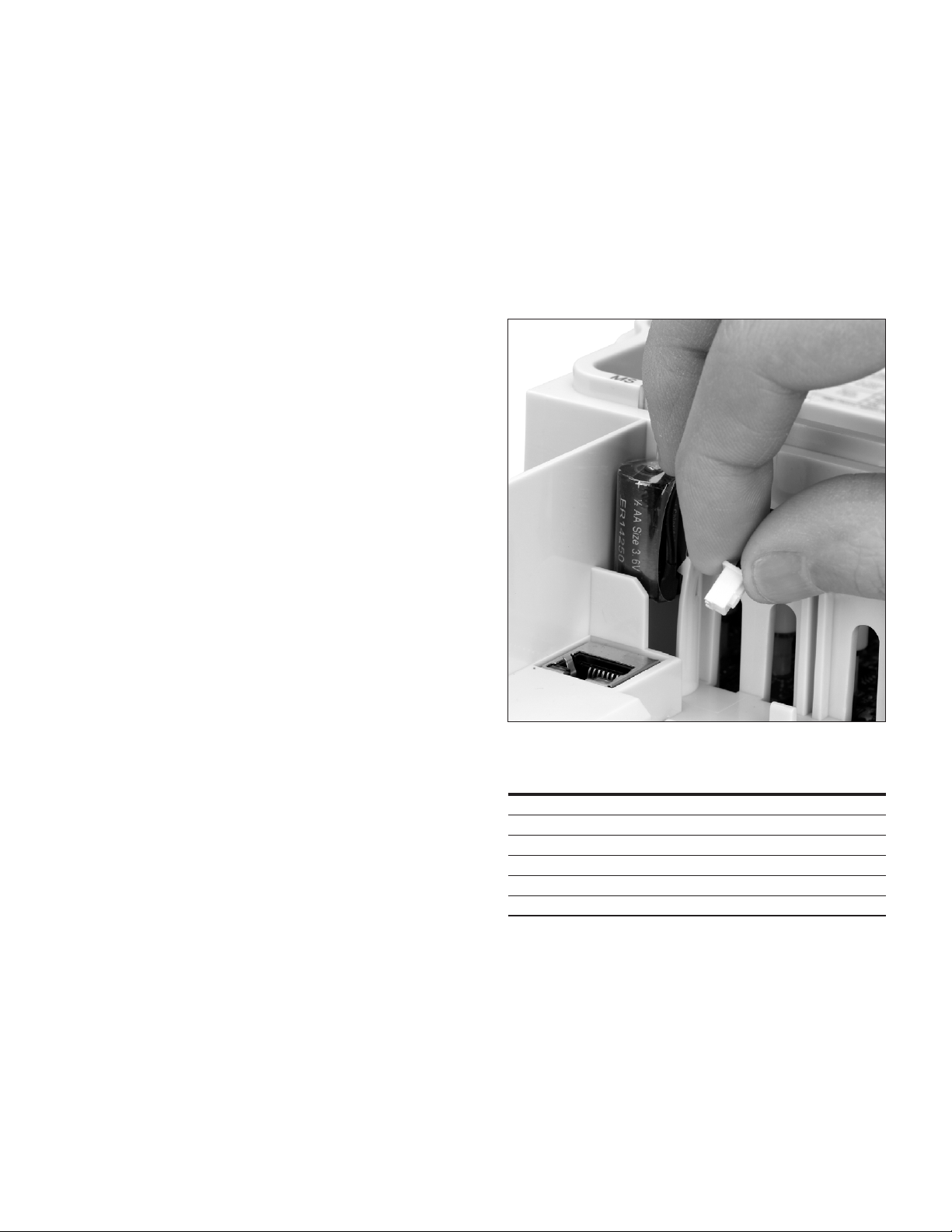
Powerxl series overview
PowerXL series overview
This series overview describes the purpose and contents of
this manual, the receiving inspection recommendations and
the DG1 Series Open Drive catalog numbering system.
How to use this manual
The purpose of this manual is to provide you with
information necessary to install, set and customize
parameters, start up, troubleshoot and maintain the Eaton
DG1 Series Variable Frequency Drive (VFD). To provide
for safe installation and operation of the equipment, read
the safety guidelines at the beginning of this manual and
follow the procedures outlined in the following chapters
before connecting power to the DG1 Series VFD. Keep
this operating manual handy and distribute to all users,
technicians and maintenance personnel for reference.
Receiving and inspection
The DG1 Series VFD has met a stringent series of factory
quality requirements before shipment. It is possible that
packaging or equipment damage may have occurred during
shipment. After receiving your DG1 Series VFD, please
check for the following:
Check to make sure that the package includes the
Instruction Leaflet (IL040016EN), Quick Start Guide
(MN040006EN), User Manual CD (CD040002EN) and
accessory packet. The accessory packet includes:
•
Rubber grommets
•
Control cable grounding clamps
•
Additional grounding screw
Inspect the unit to ensure it was not damaged during
shipment.
Make sure that the part number indicated on the nameplate
corresponds with the catalog number on your order.
If shipping damage has occurred, please contact and file a
claim with the carrier involved immediately.
If the delivery does not correspond to your order, please
contact your Eaton Electrical representative.
ote:N Do not destroy the packing. The template printed on
the protective cardboard can be used for marking the
mounting points of the DG1 VFD on the wall or in a
cabinet.
Real time clock battery activation
To activate the real time clock (RTC) functionality in the
PowerXL DG1 Series VFD, the RTC battery (already mounted
in the drive) must be connected to the control board.
Simply remove the primary drive cover, locate the RTC
battery directly below the keypad, and connect the white
2-wire connector to the receptacle on the control board.
Figure 1. RTC battery connection
Table 1. Common abbreviations
Abbreviation Definition
CT Constant torque with high overload rating (150%)
VT Variable torque with low overload rating (110%)
I
H
I
L
RTC Real Time Clock
VFD Variable Frequency Drive
High Overload (150%)
Low Overload (110%)
POWERXL DG1 SERIES VFD MN040010EN—September 2016 www.eaton.com
1
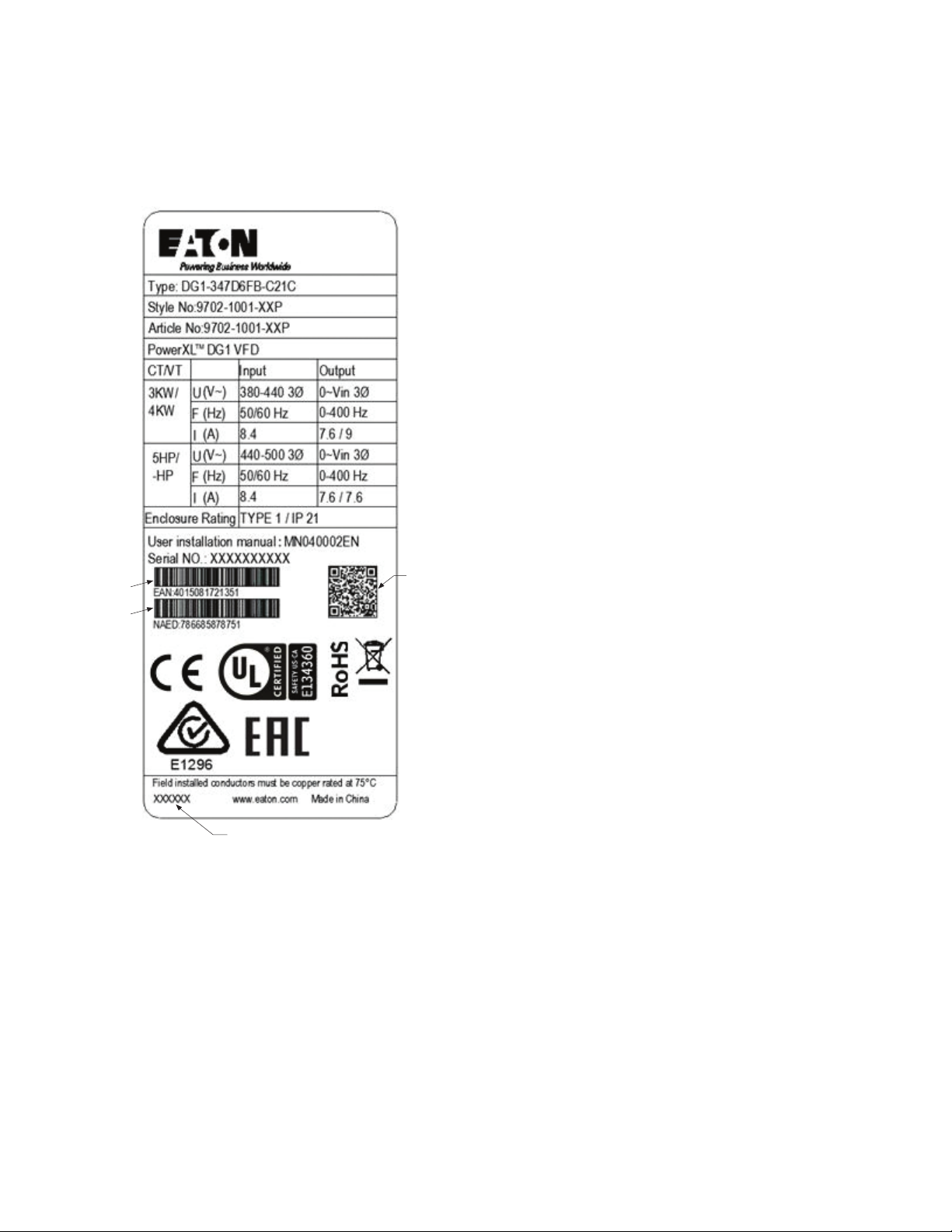
Powerxl series overview
Type, Date
Date Code: 20131118
NAED Code
Rating label
Figure 2. Rating label
Contains
EAN Code
General information
The DGI Series Drives from Eaton’s electrical business
provides a wide selection of option boards to increase the
number and type of control inputs and outputs (I/O) and
communication interfaces to provide the versatility required
for today’s demanding motor control applications.
The input and output capability is designed with modularity
in mind, comprised of option boards, each having its own
input and output configuration. The control unit is designed
to accept a total of two boards, the boards provide standard
analog and digital inputs and outputs, fieldbus capability,
and application specific hardware.
The basic, expander and adapter boards are installed in
board slots, which are parts of the control board. The I/O
boards are interchangeable between different members of
the PowerXL DG1 Series of drives.
Contains
SN, PN,
Contains
Carton labels (U.S. and Europe)
Same as rating label shown above.
2
POWERXL DG1 SERIES VFD MN040010EN—September 2016 www.eaton.com
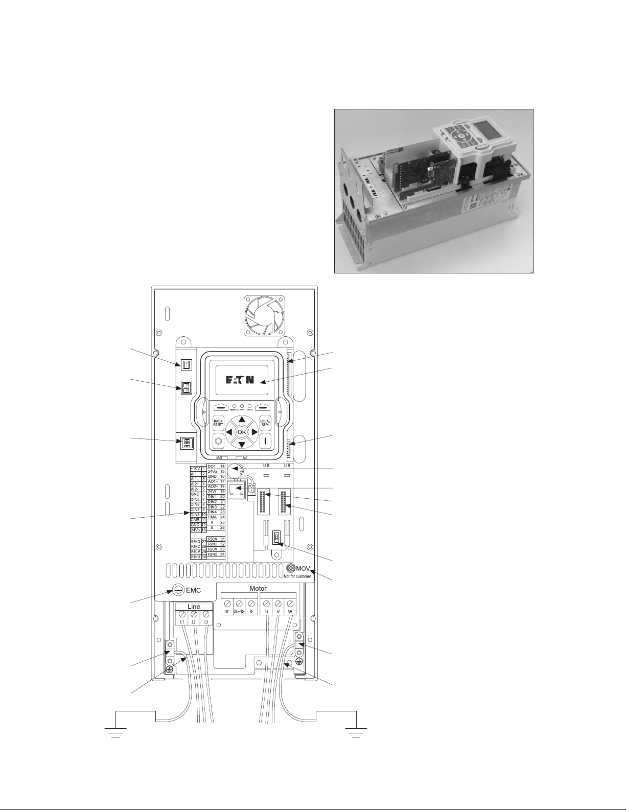
Option card slots
RS-485 Termination
AI Mode Selection
Option card slots
The control board is located inside the control unit of the
DG1 Series Drive. There are two slots, labeled A and B,
on the control board. The different option boards can be
added to any slots. For more information see “PowerXL
DG1 Option Board Summary.” When the DG1 Series Drive
is assembled at the factory, no option boards are installed
in slots A and B. If an incorrect board is plugged into either
slot, the board will not work, but there is no danger to
personal or for equipment damage.
Figure 4. Drive control board layout showing option
card slots
Fan Power Wire
STO
Figure 3. DG1 series control board location
Connect DSP Part
to Power Board
Keypad
Control I/O
Terminals
Removable
EMC Screw
Line Ground
Clamp Location
Grounding
Strap Location
Connect MCU Part
123
ON
ON
1
to Power Board
Battery (Standard)
RJ45 EtherNet/IP,
Modbus TCP
Optional Card A
Optional Card B
Resistor
Removable
MOV Screw
Motor Ground
Clamp Location
Grounding
Strap Location
Line Side Motor
POWERXL DG1 SERIES VFD MN040010EN—September 2016 www.eaton.com
3
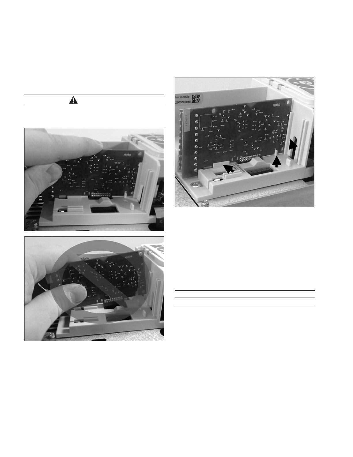
Option card slots
Installing DG1 option board
Remove Utility line and control power from the PowerXL
DG1 series drive. Install the option board in one of the
slots available on the control board. To insert and remove
the board, hold it in a horizontally straight position to avoid
twisting the connector pins.
CAUTION
To prevent board damage, option cards and fieldbus boards
must not be installed, removed or replaced while utility line
or control power is applied to the PowerXL Drive.
Verify the board fits tightly in the metal clamp and plastic
groove. If the board seems to be difficult to install in the
slot, you should confirm that you are using one of the
allowed slots for the option board.
ote:N Check that the DIP switch settings on the board
correspond to your need.
Control wiring
Digital I/O and 24 Vdc can use Stranded Cu or Solid Cu wire
as specified below. Analog signal PT100 must use shielded
cables. Table 2 shows the wire sizes available. I/O terminals
allow for 5.00 mm connectors.
Table 2. Wire sizes
Wire type Wire size Terminal torque
Solid Cu –90 °C 12–28 AWG (0.2~2.5 mm2) 4.5 in-lb (0.5 Nm)
Stranded Cu –90 °C 12–30 AWG (0.2~2.5 mm2) 4.5 in-lb (0.5 Nm)
4
POWERXL DG1 SERIES VFD MN040010EN—September 2016 www.eaton.com
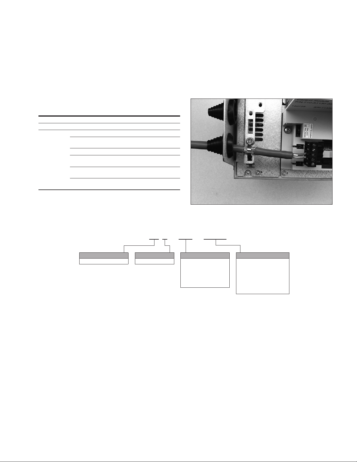
Option card slots
DX G – NET – PROFB
EMC directive
For the electrical equipment installed in the EMC, directive
states that the equipment must not disturb the environment
and must be immune to other electromagnetic disturbances
Control cable grounding
It is recommended that the shielded cables be grounded
as shown in Figure 5. Strip the cable insulation required
allowing attachment to the frame with the grounding clamp.
in the environment. Table 3 indicates the requirements for
the control wiring to meet this directive.
Figure 5. Control cable grounding
Table 3. Control wiring requirements
Item Directive
Product
Safety
EMC (at default
settings)
IEC 61800-2
UL 508C, IEC / EN 61800-5-1
Immunit y: EN / IEC 61800-3, 2nd environment
Radiated emissions: EN / IEC 61800-3 (Transient Testing
included), 1st environment
Conducted emissions: EN / IEC 61800-3
Category C1: is possible with external filter connected to
drive. Please consult factor y
Category C2: with internal filter maximum of 10m motor
cablelength
Category C 3: with internal filter maximum of 50m motor
cable length
Table 4. PowerXL series—DG1 general purpose drive option boards
DX = PowerXL Drive
ote:N
Will be available 2017.
Basic naming
Series
G = General purpose
Type
NET = Communication card
EXT = I/O card
ACC = Accessory
SPR = Spare part
KEY = Keypad
CBL = Cable
Function
PROFIBUS = PROFIBUS
DEVICENET = DeviceNet
CANopen = CANopen
SWD = SmartWire
See Volume 6, CA08100007E,
Tab 2, PowerXL DG1 Accessories
for full offering
1
POWERXL DG1 SERIES VFD MN040010EN—September 2016 www.eaton.com
5

Modbus RTU On-Board communications
Modbus RTU On-Board communications
The PowerXL DG1 product can be controlled via Modbus®
RTU through the on-board RS-485 terminals.
Figure 6. Connection diagram
The figure shows a typical arrangement with a host
computer (master) and any number maximum 31 slaves
of frequency inverters. Each frequency inverter has a
unique address in the network. This addressing is executed
individually for each AFD via the communication parameters.
The electrical connection between master and the slaves
connected in parallel are implemented via the serial
interface A-B (A = negative, B = positive) with a shielded
RS-485 twisted pair cable.
6
POWERXL DG1 SERIES VFD MN040010EN—September 2016 www.eaton.com
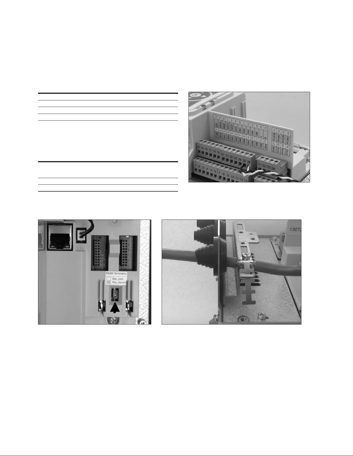
Modbus RTU On-Board communications
Modbus RTU specifications
Communication board connections
Table 5. Connections
Item Description
Interface
Data Transfer Method
Transfer Cable
Electrical Isolation
RS-485, half-duplex
Twisted pair (1 pair and shield)
Communications
Table 6. Communications
Item Description
Modbus RTU
Baud Rate
Addresses
Figure 8. Termination resistor and shielding
As described in “Modicon Modbus Protocol
Reference Guide”
found at. http.//public.modicon.com/
9600,19200,38400,57600,115200
1 to 247
Connections
The RS-485 communication port is connected via the AandB
terminals on the drives control board.
Figure 7. Terminal wiring
POWERXL DG1 SERIES VFD MN040010EN—September 2016 www.eaton.com
7
 Loading...