

Eaton DG1-347D6FB-C21C Quick Start Manual
PowerXL DG1 Series VFD
Courtesy of CMA/Flodyne/Hydradyne ▪ Motion Control ▪ Hydraulic ▪ Pneumatic ▪ Electrical ▪ Mechanical ▪ (800) 426-5480 ▪ www.cmafh.com
Quick Start Guide
Effective March 2014
New Information
CONTENTS
Step 1—PowerXL DG1 Series Overview . . . . . . . 1
Step 2—Keypad Operation Overview . . . . . . . . . 3
Step 3—Menu Navigation . . . . . . . . . . . . . . . . . . 6
Step 4—Startup Wizard . . . . . . . . . . . . . . . . . . . . 8
Step 5—Standard Parameter List . . . . . . . . . . . . 9
Step 6—Faults and Warning Codes . . . . . . . . . . . 26

Courtesy of CMA/Flodyne/Hydradyne ▪ Motion Control ▪ Hydraulic ▪ Pneumatic ▪ Electrical ▪ Mechanical ▪ (800) 426-5480 ▪ www.cmafh.com
Step 1—PowerXL DG1 Series Overview
Courtesy of CMA/Flodyne/Hydradyne ▪ Motion Control ▪ Hydraulic ▪ Pneumatic ▪ Electrical ▪ Mechanical ▪ (800) 426-5480 ▪ www.cmafh.com
Step 1—PowerXL DG1 Series Overview
This chapter describes the purpose and contents of this
manual, the receiving inspection recommendations and the
DG1 Series Open Drive catalog numbering system.
How to Use this Manual
The purpose of this manual is to provide you with information
necessary to install, set and customize parameters, start up,
troubleshoot and maintain the Eaton DG1 Series adjustable
frequency drive (AFD). To provide for safe installation and
operation of the equipment, read the safety guidelines at the
beginning of this manual and follow the procedures outlined
in the following chapters before connecting power to the
DG1 Series AFD. Keep this operating manual handy and
distribute to all users, technicians and maintenance
personnel for reference.
Receiving and Inspection
The DG1 Series AFD has met a stringent series of factory
quality requirements before shipment. It is possible that
packaging or equipment damage may have occurred during
shipment. After receiving your DG1 Series AFD, please
check for the following:
Check to make sure that the package includes the Instruction
Leaflet (IL040016EN), Quick Start Guide (MN040006EN),
User Manual CD (CD040002EN) and accessory packet. The
accessory packet includes:
●
Rubber grommets
●
Control cable grounding clamps
●
Additional grounding screw
Inspect the unit to ensure it was not damaged during
shipment.
Make sure that the part number indicated on the nameplate
corresponds with the catalog number on your order.
If shipping damage has occurred, please contact and file a
claim with the carrier involved immediately.
If the delivery does not correspond to your order, please
contact your Eaton Electrical representative.
Note: Do not destroy the packing. The template printed
on the protective cardboard can be used for marking
the mounting points of the DG1 AFD on the wall or
in a cabinet.
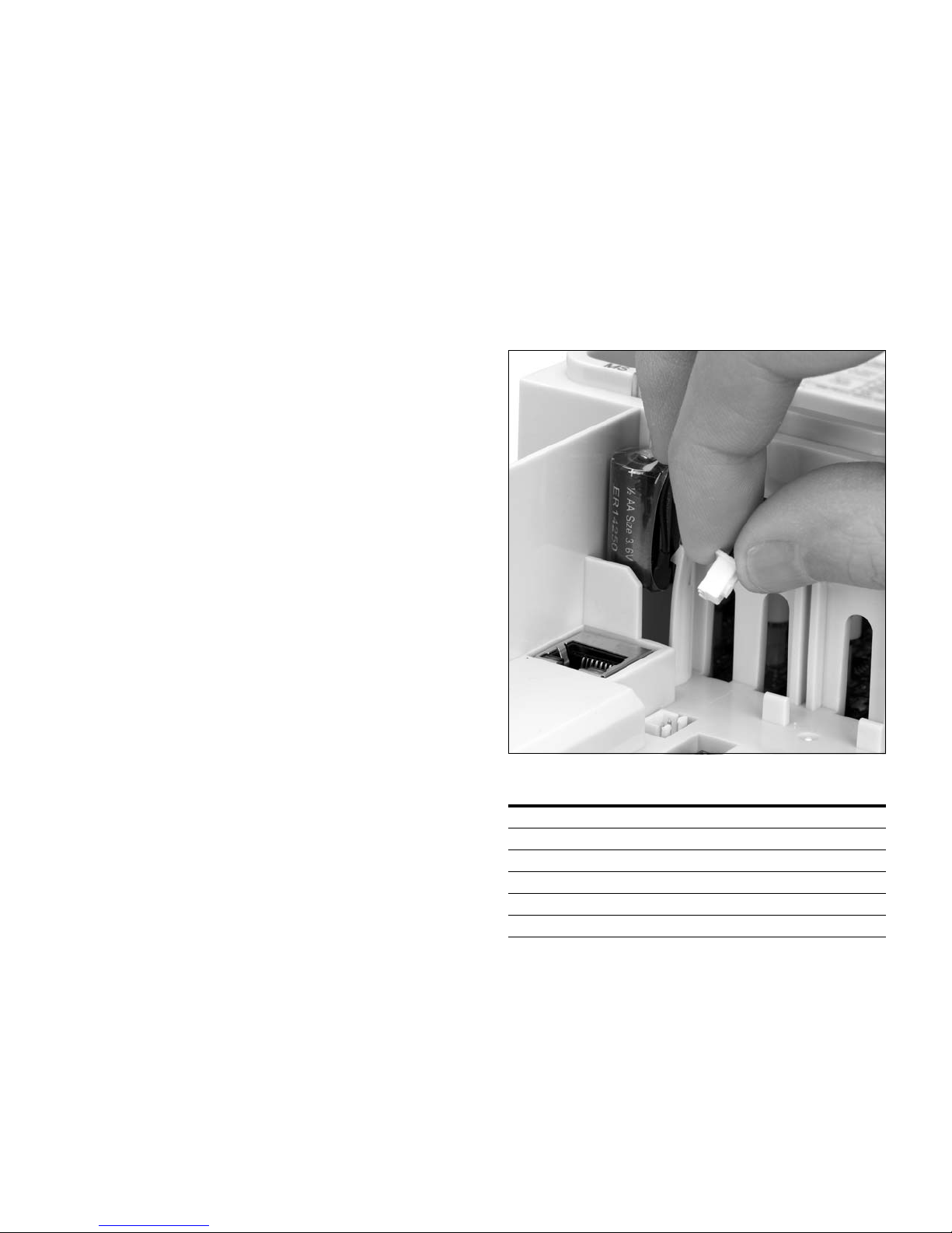
Real Time Clock Battery Activation
To activate the real time clock (RTC) functionality in the
PowerXL DG1 Series AFD, the RTC battery (already mounted
in the drive) must be connected to the control board.
Simply remove the primary drive cover, locate the RTC
battery directly below the keypad, and connect the white
2-wire connector to the receptacle on the control board.
Figure 1. RTC Battery Connection
Table 1. Common Abbreviations
Abbreviation Definition
CT Constant torque with high overload rating (150%)
VT Variable torque with low overload rating (110%)
I
H
I
L
AFD Adjustable Frequency Drive
VFD Variable Frequency Drive
High Overload (150%)
Low Overload (110%)
PowerXL DG1 Series Adjustable Frequency Drives MN040012EN—March 2014 www.eaton.com 1
Step 1—PowerXL DG1 Series Overview
Contains
EAN Code
Date Code: 20131118
Contains
NAED Code
Programmable
Soft Key 2
Change Control
Place Between
Local and Remote
Move Cursor
Right
Start Button
Stop Button
Back/Reset
Button
Increase
Value Scroll
Menu Up
Programmable
Soft Key 1
Decrease Value
Scroll Menu Down
Move Cursor
Left
Enter Menu
Conrm Selection
Courtesy of CMA/Flodyne/Hydradyne ▪ Motion Control ▪ Hydraulic ▪ Pneumatic ▪ Electrical ▪ Mechanical ▪ (800) 426-5480 ▪ www.cmafh.com
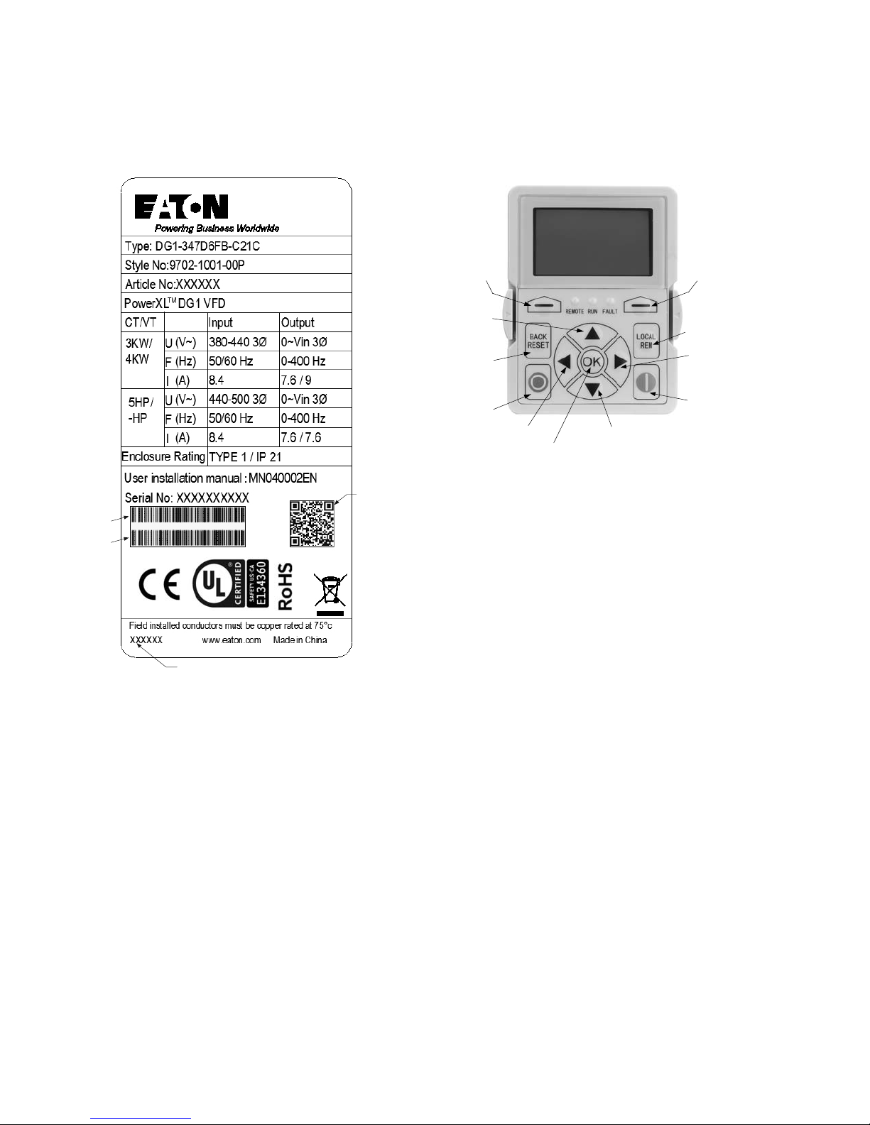
Rating Label
Figure 2. Rating Label
Contains
SN, PN,
Type, Date
Keypad Overview
Figure 3. Keypad and Display
Carton Labels (U.S. and Europe)
Same as rating label shown above.
2 PowerXL DG1 Series Adjustable Frequency Drives MN040012EN—March 2014 www.eaton.com
Step 2—Keypad Operation Overview
Courtesy of CMA/Flodyne/Hydradyne ▪ Motion Control ▪ Hydraulic ▪ Pneumatic ▪ Electrical ▪ Mechanical ▪ (800) 426-5480 ▪ www.cmafh.com
The keypad is the interface between the drive and the user.
It features an LCD display, 3 LED lights and 11 buttons. With
the control keypad, it is possible to control the speed of a
motor, to supervise the state of the equipment and to set the
frequency converter’s parameters. See Figure 3.
Keypad Buttons
Step 2—Keypad Operation Over view
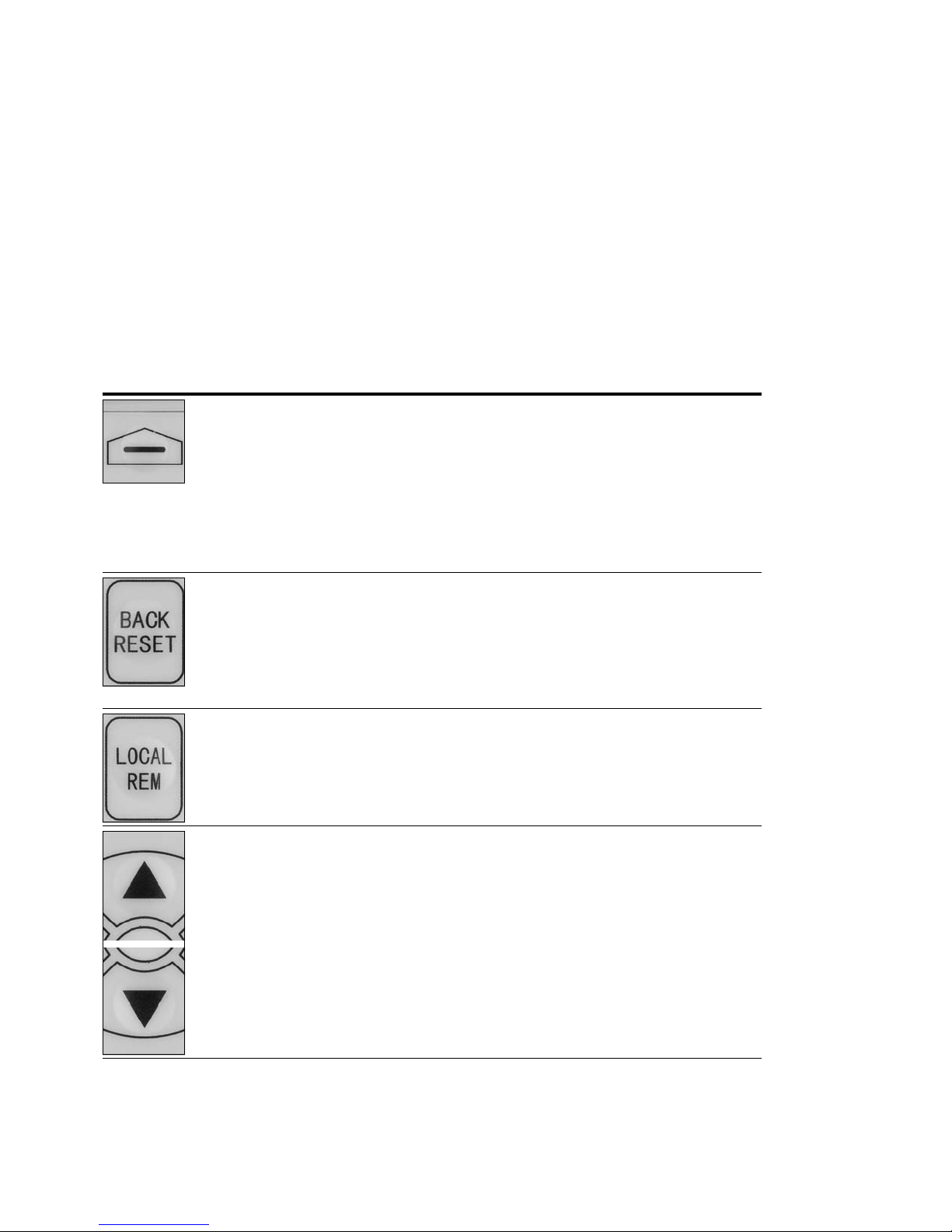
Buttons Description
Table 2. Keypad Buttons
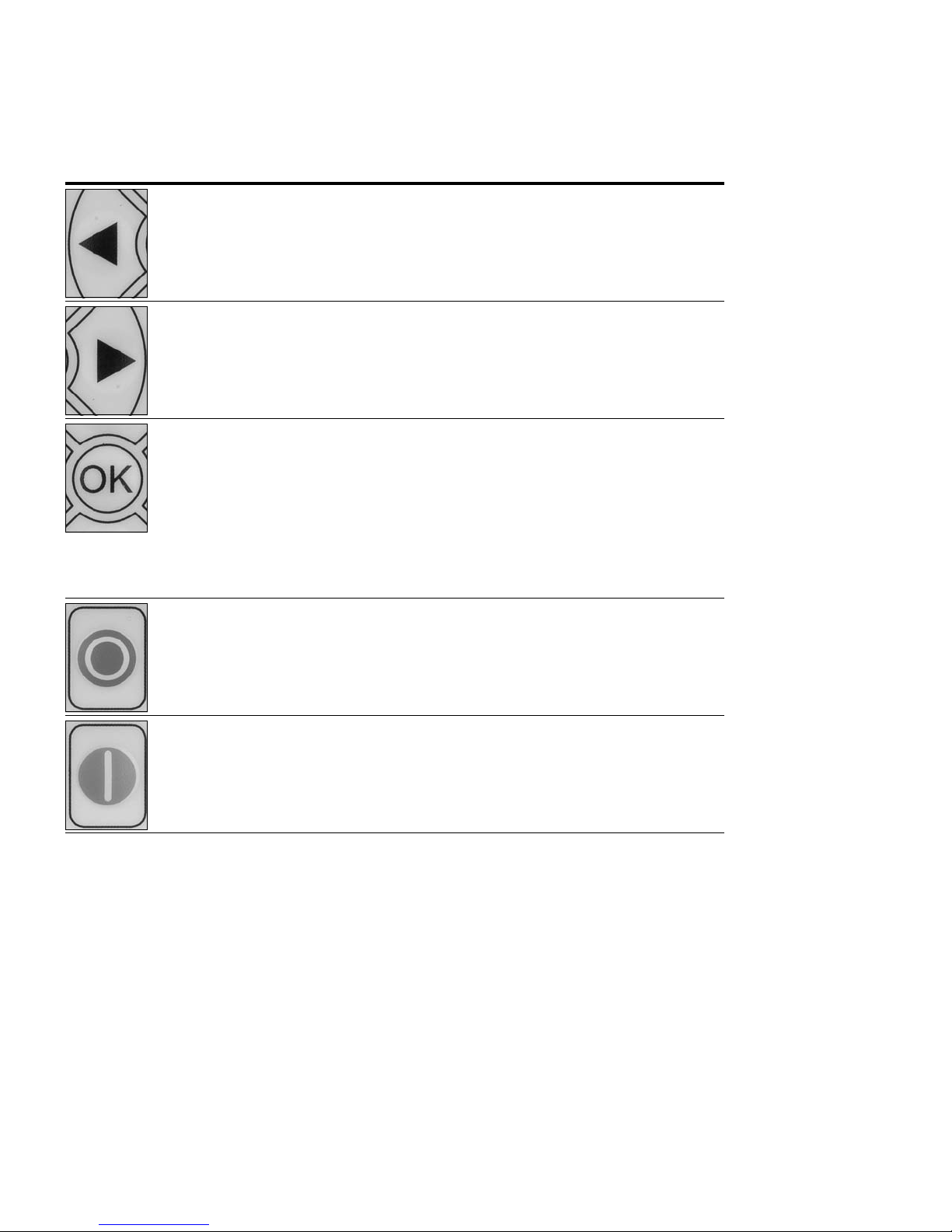
Icon Button Description
Soft Key 1,
Soft Key 2
Back/Reset Back/Reset:
Local/Remote Local/Remote:
Soft Key 1, Soft Key 2:
The functions of these two buttons shall be the following:
Forward/Reverse, this shall change motor’s run direction.
Reset, this shall ask MCU to reset after some parameters are modified.
• Menu, this shall return to main menu.
• Details, this shall display the details of the fault.
• Bypass, this shall make drive go into bypass.
• Jog, this shall activate jog.
• Favorite, this shall add this parameter to the Favorite menu.
• Delete, this shall delete this parameter from the Favorite menu.
This button has three integrated functions. The button operates as backward button
during normal mode.
In edit mode, it is used as cancel operate. It is also used to reset faults when faults occur.
• Backs up one step.
• Cancels Modify in edit mode.
• Resets the active faults (all the active faults shall be reset by pressing this button
more than 2s in any page).
Switches between LOCAL and REMOTE control for start and speed reference. The control
locations corresponding to local and remote shall be selected within an application.
Up
Down
PowerXL DG1 Series Adjustable Frequency Drives MN040012EN—March 2014 www.eaton.com 3
Up and Down Arrows:
• Move either up or down a menu list to select the desired menu item.
• Editing a parameter bit by bit, while the active digit is scrolled.
• Increase/decrease the reference value of the selected parameter.
• In parameter comparison mode, scroll through the parameters of which current
value is different from comparison parameter value.
• In parameter page when in read mode, move to the previous or next brother
parameter of this parameter.
Step 2—Keypad Operation Over view
Courtesy of CMA/Flodyne/Hydradyne ▪ Motion Control ▪ Hydraulic ▪ Pneumatic ▪ Electrical ▪ Mechanical ▪ (800) 426-5480 ▪ www.cmafh.com
Table 2. Keypad Buttons, continued
Icon Button Description
Left Left Arrow:
• Navigation button, movement to left when editing a parameter digit by digit.
• Backs up one step.
Right Right Arrow:
• Enter parameter group mode.
• Enter parameter mode from group mode.
• Enter parameter whole edit mode when this parameter can be written.
• Enter parameter bit by bit edit mode from whole edit mode.
• Navigation button, movement to right when editing a parameter bit by bit.
OK OK:
• To clear all the Fault History if pressed for more than 5s (including 5s) in any
page.
• This button is used in the parameter edit mode to save the parameter setting.
• To confirm the start-up list at the end of the Start-Up Wizard.
• To confirm the comparison item in parameters comparison mode.
The following is the same with Right key:
• Enter parameter whole edit mode when this parameter can be written.
• Enter parameter group mode.
• Enter parameter mode from group mode.
Stop Stop:
This button operates as motor stop button for normal operation when the “Keypad” is
selected as the control source and keypad stop button is active, or stop button is always
enabled regardless of control source.
• Motor stop from the keypad.
Start Start:
This button operates as motor start button for normal operation when the “Keypad” is
selected as the active control source.
4 PowerXL DG1 Series Adjustable Frequency Drives MN040012EN—March 2014 www.eaton.com
Step 2—Keypad Operation Over view
Drive Status
Direction Status
Control Place
Menu Location
Soft Key 2
Function Label
Soft Key 1
Function Label
Real Time Clock
(hh:mm)
Active
Selection
Courtesy of CMA/Flodyne/Hydradyne ▪ Motion Control ▪ Hydraulic ▪ Pneumatic ▪ Electrical ▪ Mechanical ▪ (800) 426-5480 ▪ www.cmafh.com
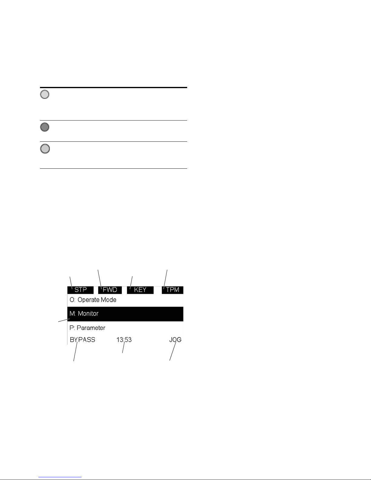
LED Lights
Table 3. LED State Indicators
Indicator Description
Run:
Indicates that the VFD is running and controlling the load in
Run
Drive or Bypass.
Blinks when a stop command has been given but the drive is
still ramping down.
Fault:
Turn on when there is one or more active drive fault(s).
Fault
Blinks when there is one or more active drive warning(s).
Local/Remote:
Local: If the local control place is selected, turn off the light.
Remote
Remote: If the remote control place is selected, turn on the
light.
LCD Display
The keypad LCD indicates the status of the motor and the
drive and any faults in motor or drive functions. On the LCD,
the user sees information about the current location in the
menu structure and the item displayed.
Overview
Five lines shall be displayed in the screen. General view is as
following in Figure 4.
Figure 4. General View of LCD
The lines definition is as below:
The first line is State line, shows:
●
RUN / STP / NRD—If motor is running, the run state shall
display “RUN”, otherwise the state display “STP”. “RUN”
blinks when the stop command is sent but the drive is
decelerating. “NRD” is displayed if the drive is not ready or
does not have a signal
●
FWD / REV—If the motor running direction is clockwise,
display “FWD”, otherwise display “REV”
●
KEY / I/O / BPS / BUS—If it is in bypass currently, display
“BPS”; otherwise, if the current control source is I/O
terminal, display “I/O”. If it is keypad, then display “KEY”;
otherwise display “BUS”
●
PAR / MON / FLT / OPE / QSW / FAV / TPM—If the
current page is parameter menu, display “PAR”; If monitor
menu, then display “MON”; If fault menu, then display
“FLT”; If operation menu, then display “OPE”; If quick
start wizard, then display “QSW”; If optional card menu,
then display “BOA”; If favorite menu, then display “FAV”;
If main menu, then display “TPM”
The second line is Code line, shows the menu code.
The third line is Name line, shows the menu name or
parameters name.
The fourth line is Value line, shows the submenu name or
parameters value.
The fifth line is Soft key line, the functions of Soft key 1 and
Soft key 2 are changeable, and the real time is in the middle.
PowerXL DG1 Series Adjustable Frequency Drives MN040012EN—March 2014 www.eaton.com 5

Step 3—Menu Navigation
Courtesy of CMA/Flodyne/Hydradyne ▪ Motion Control ▪ Hydraulic ▪ Pneumatic ▪ Electrical ▪ Mechanical ▪ (800) 426-5480 ▪ www.cmafh.com
Step 3—Menu Navigation
Menu Structure
Table 4. Keypad Menus
Item Description Item Description Item Description
Monitor M1—Output Frequency M24—Interval 3 Parameters P1—Basic Parameters Fault F1—Active Fault
M2—Freq Reference M25—Interval 4 P2—Analog Input F2—History Fault
M3—Motor Speed M26—Interval 5 P3—Digital Input Optional Boards B1—SlotA
M4—Motor Current M27—Timer 1 P4—Analog Output B2—SlotB
M5—Motor Torque M28—Timer 2 P5—Digital Output Favorite —
M6—Motor Power M29—Timer 3 P6—Logic Function Operate Mode O1—Output Frequency
M7—Motor Voltage M30—PID1 Set Point P7—Drive Control O2—Freq Reference
M8—DC-link Voltage M31—PID1 Feedback P8—Motor Control O3—Motor Speed
M9—Unit Temperature M32—PID1 Error Value P9—Protections O4—Motor Current
M10—Motor Temperature M33—PID1 Output P10—PID Controller1 05—Motor Torque
M11—Torque Reference M34—PID1 Status P11—PID Controller2 O6—Motor Power
M12—Analog Input 1 M35—PID2 Set Point P12—Preset Speed O7—Motor Voltage
M13—Analog Input 2 M36—PID2 Feedback P13—Torque Control O8—DC-Link Voltage
M14—Analog Output 1 M37—PID2 Error Value P14—Brake O9—Unit Temperature
M15—Analog Output 2 M38—PID2 Output P15—Fire Mode O10—Motor Temperature
M16—DI1, DI2, DI3 M39—PID2 Status P16—Second Motor Para O11—Keypad Torque Ref
M17—DI4, DI5, DI6 M40—Running Aux Drives P17—Bypass 012—Keypad Reference
M18—DI7, DI8 M41—PT100 Temp P18—Multi-Pump Ctrl Startup Wizard S—Startup Wizard
M19—DO1 M42—Last Active Fault P19—Real Time Clock
M20—RO1, RO2, RO3 M43—RTC Battery Status P20—Communication
M21—TC1, TC2, TC3 M44—I
M22—Interval 1 M45—Energy Savings
M23—Interval 2 M46—Multi-Monitoring
nstance Motor Power
P21—System
Note: Will vary depending on application selected.
6 PowerXL DG1 Series Adjustable Frequency Drives MN040012EN—March 2014 www.eaton.com
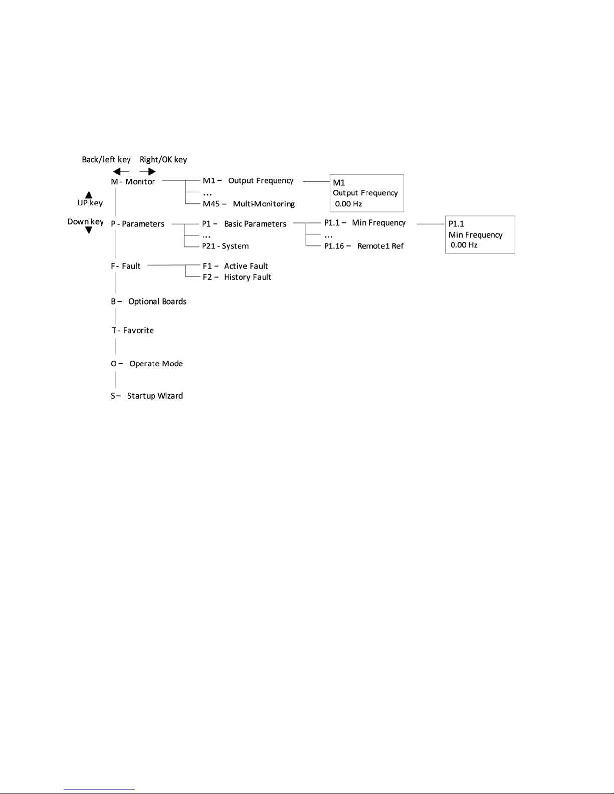
Menu Navigation
Courtesy of CMA/Flodyne/Hydradyne ▪ Motion Control ▪ Hydraulic ▪ Pneumatic ▪ Electrical ▪ Mechanical ▪ (800) 426-5480 ▪ www.cmafh.com
This section provides basic instruction on navigating each
section in the menu structure.
Figure 5. Main Menu Navigation
Step 3—Menu Navigation
PowerXL DG1 Series Adjustable Frequency Drives MN040012EN—March 2014 www.eaton.com 7
Step 4—Startup Wizard
Courtesy of CMA/Flodyne/Hydradyne ▪ Motion Control ▪ Hydraulic ▪ Pneumatic ▪ Electrical ▪ Mechanical ▪ (800) 426-5480 ▪ www.cmafh.com
Step 4—Startup Wizard
Startup Wizard
In the Startup Wizard, you will be prompted for essential
information needed by the drive so that it can start
controlling your process. In the Wizard, you will need
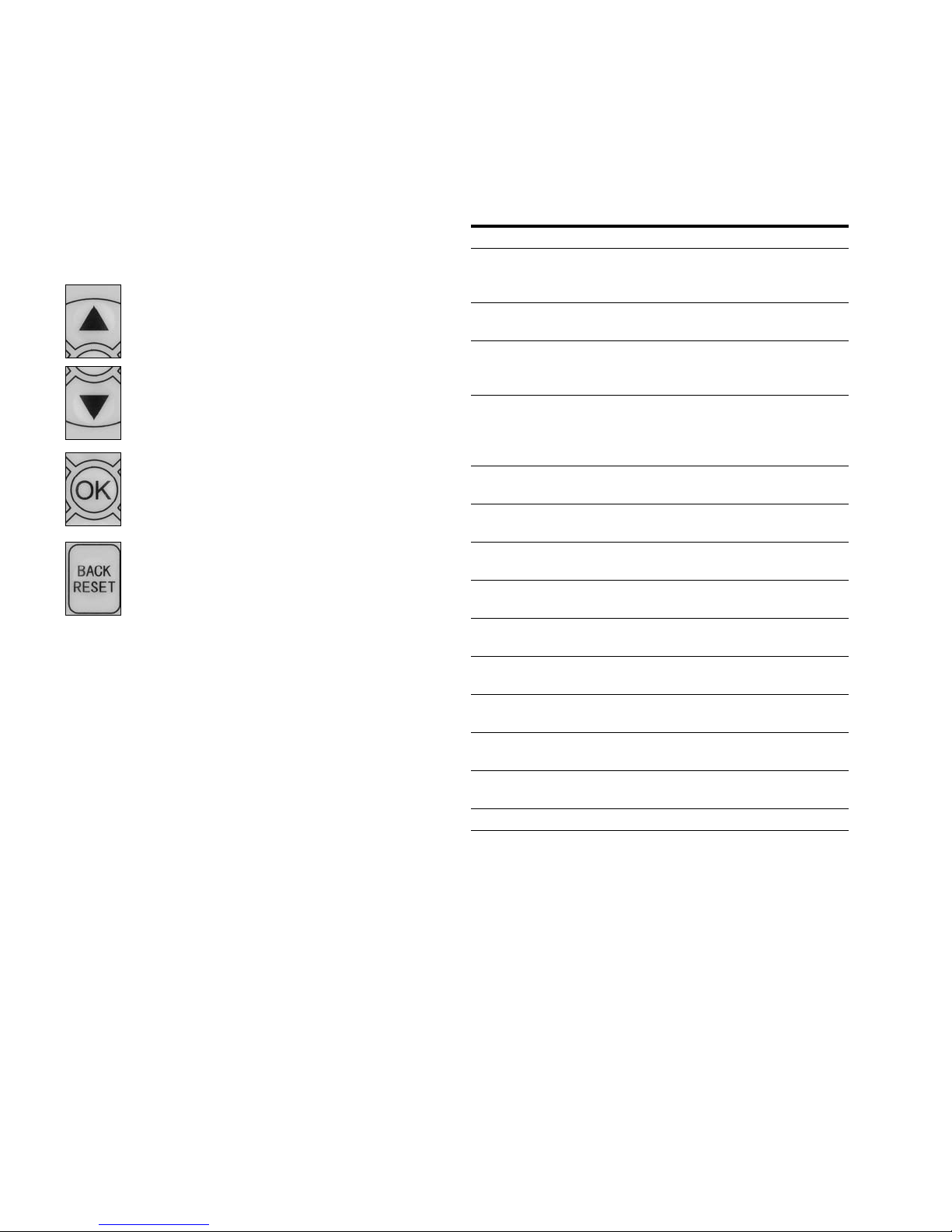
the following keypad buttons:
Up/Down buttons.
Use these to change value.
OK button.
Confirm selection with this button, and enter into
next question.
Back/Reset button.
If this button was pressed at the first question,
the Startup Wizard will be cancelled.
Once you have connected power to your Eaton PowerXL
DG1 frequency converter, and the Startup Wizard is enabled,
follow these instructions to easily set up your drive.
Table 5. Startup Wizard Instructions
Item Description
1 Startup Wizard Press OK?
2 Language 0 = English
1 = ѝ᮷
2 = Deutsch
3 Real Time Clock yy.mm.dd
hh:mm:ss
4 Daylight Saving 0 = Off
1 = EU
2 = US
5 Application 0 = Standard
1 = Multi-Pump
2 = Multi-PID
3 = Multi-Purpose
6 Min Frequency Min: 0.00Hz
Max: Max Frequency
7 Max Frequency Min: Min Frequency
Max: 400.00Hz
8 Motor Nom Current Min: 0.1A
Max: 500.0A
9 Current Limit Min: Ih*1/10
Max: Ih*2
10 Motor Nom Speed Min: Ih*1/10
Max: Ih*2
11 Motor PF Min: 0.30
Max: 1.0
12 Motor Nom Volt Min: 180V
Max: 690V
13 Motor Nom Freq Min: 30.00 Hz
Max: 400.00 Hz
14 Motor Nom Power Min: 0.1 kW
Max:5000.0 kW
15 Application Mini-Wizard Press OK?
8 PowerXL DG1 Series Adjustable Frequency Drives MN040012EN—March 2014 www.eaton.com
Now the Startup Wizard is done. It won’t show again when
next power up. If you want to reset it, please set the Startup
Wizard (P21.1.9) or select it from the main menu screen to
enable and cycle the power to the drive.
 Loading...