

Eaton DG1-32012FB-C21C, DG1-323D7FB-C21C, DG1-324D8FB-C21C, DG1-32025FB-C21C, DG1-32048FB-C21C Installation Manual
...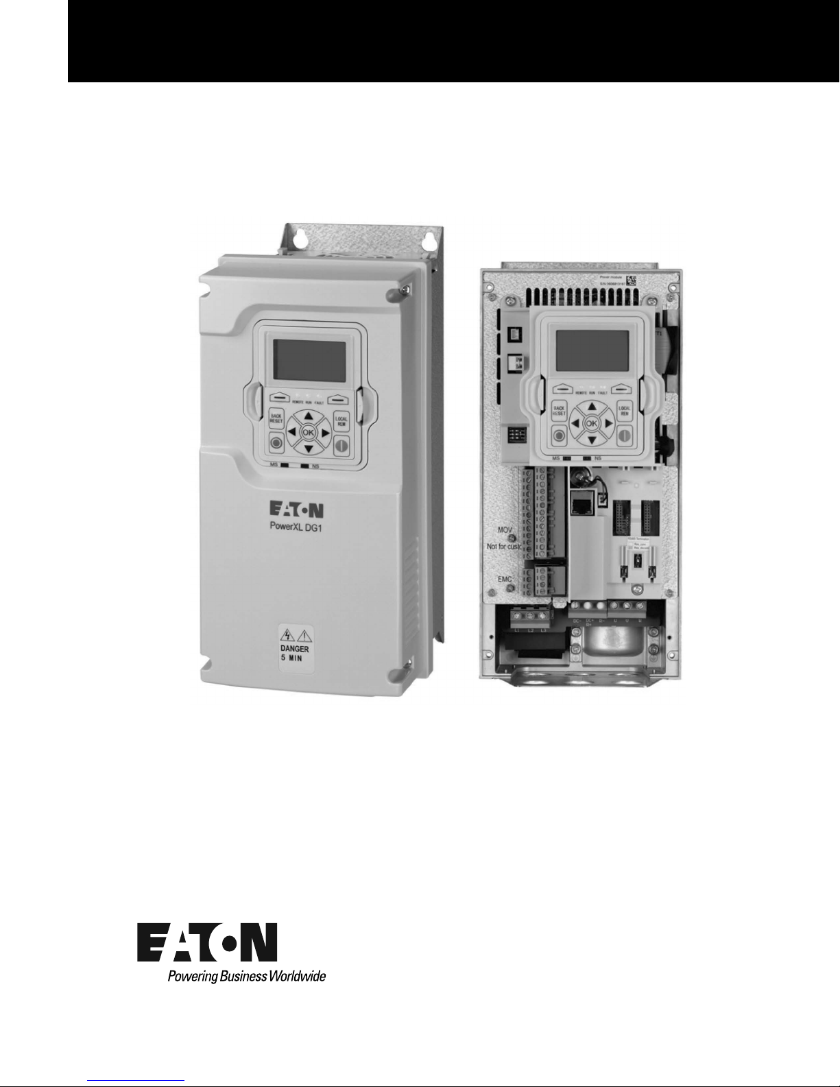
PowerXL DG1 Series VFD
Installation Manual
Effective March 2014
New Information


Disclaimer of Warranties and Limitation of Liability
The information, recommendations, descriptions, and safety notations in this document are
based on Eaton’s experience and judgment and may not cover all contingencies. If further
information is required, an Eaton sales office should be consulted. Sale of the product shown
in this literature is subject to the terms and conditions outlined in appropriate Eaton selling
policies or other contractual agreement between Eaton and the purchaser.
THERE ARE NO UNDERSTANDINGS, AGREEMENTS, WARRANTIES, EXPRESSED OR
IMPLIED, INCLUDING WARRANTIES OF FITNESS FOR A PARTICULAR PURPOSE OR
MERCHANTABILITY, OTHER THAN THOSE SPECIFICALLY SET OUT IN ANY EXISTING
CONTRACT BETWEEN THE PARTIES. ANY SUCH CONTRACT STATES THE ENTIRE
OBLIGATION OF EATON. THE CONTENTS OF THIS DOCUMENT SHALL NOT BECOME
PART OF OR MODIFY ANY CONTRACT BETWEEN THE PARTIES.
In no event will Eaton be responsible to the purchaser or user in contract, in tort (including
negligence), strict liability, or otherwise for any special, indirect, incidental, or consequential
damage or loss whatsoever, including but not limited to damage or loss of use of equipment,
plant or power system, cost of capital, loss of power, additional expenses in the use of
existing power facilities, or claims against the purchaser or user by its customers resulting
from the use of the information, recommendations, and descriptions contained herein. The
information contained in this manual is subject to change without notice.
Cover Photo: Eaton PowerXL DG1 Series Drive
PowerXL DG1 Series VFD
PowerXL DG1 Series VFD MN040002EN—March 2014 www.eaton.com i

PowerXL DG1 Series VFD
Support Services
Support Services
The goal of Eaton is to ensure your greatest possible satisfaction with the operation of our
products. We are dedicated to providing fast, friendly, and accurate assistance. That is why
we offer you so many ways to get the support you need. Whether it is by phone, fax, or
email, you can access Eaton’s support information 24 hours a day, seven days a week.
Our wide range of services is listed below.
You should contact your local distributor for product pricing, availability, ordering, expediting,
and repairs.
Website
Use the Eaton Website to find product information. You can also find information on local
distributors or Eaton’s sales offices.
Website Address
www.eaton.com/drives
EatonCare Customer Support Center
Call the EatonCare Support Center if you need assistance with placing an order, stock
availability or proof of shipment, expediting an existing order, emergency shipments, product
price information, returns other than warranty returns, and information on local distributors or
sales offices.
Voice: 877-ETN-CARE (386-2273) (8:00 a.m.–6:00 p.m. EST)
After-Hours Emergency: 800-543-7038 (6:00 p.m.–8:00 a.m. EST)
Drives Technical Resource Center
Voice: 877-ETN-CARE (386-2273) option 2, option 6
(8:00 a.m.–5:00 p.m. Central Time U.S. [UTC –6])
email: TRCDrives@Eaton.com
For Customers in Europe, Contact
Phone: +49 (0) 228 6 02-3640
Hotline: +49 (0) 180 5 223822
email: AfterSalesEGBonn@Eaton.com
www.eaton.com/moeller/aftersales
ii PowerXL DG1 Series VFD MN040002EN—March 2014 www.eaton.com

Table of Contents
SAFETY
Before Commencing the Installation . . . . . . . . . . . . . . . . . . . . . . . . . . . . . . . . . vii
Definitions and Symbols . . . . . . . . . . . . . . . . . . . . . . . . . . . . . . . . . . . . . . . . . . viii
Hazardous High Voltage . . . . . . . . . . . . . . . . . . . . . . . . . . . . . . . . . . . . . . . . . . . viii
Warnings and Cautions . . . . . . . . . . . . . . . . . . . . . . . . . . . . . . . . . . . . . . . . . . . viii
Motor and Equipment Safety . . . . . . . . . . . . . . . . . . . . . . . . . . . . . . . . . . . . . . . xi
CHAPTER 1—DG1 SERIES OVERVIEW
How to Use this Manual . . . . . . . . . . . . . . . . . . . . . . . . . . . . . . . . . . . . . . . . . . 1
Receiving and Inspection . . . . . . . . . . . . . . . . . . . . . . . . . . . . . . . . . . . . . . . . . . 1
Real Time Clock Battery Activation . . . . . . . . . . . . . . . . . . . . . . . . . . . . . . . . . . 1
Rating Label . . . . . . . . . . . . . . . . . . . . . . . . . . . . . . . . . . . . . . . . . . . . . . . . . . . . 2
Carton Labels (U.S. and Europe) . . . . . . . . . . . . . . . . . . . . . . . . . . . . . . . . . . . . 2
Catalog Number System . . . . . . . . . . . . . . . . . . . . . . . . . . . . . . . . . . . . . . . . . . 3
Power Ratings and Product Selection . . . . . . . . . . . . . . . . . . . . . . . . . . . . . . . . 4
Replacement Parts . . . . . . . . . . . . . . . . . . . . . . . . . . . . . . . . . . . . . . . . . . . . . . . 6
CHAPTER 2—ENGINEERING CONSIDERATIONS
Introduction . . . . . . . . . . . . . . . . . . . . . . . . . . . . . . . . . . . . . . . . . . . . . . . . . . . . 9
Electrical Power Network . . . . . . . . . . . . . . . . . . . . . . . . . . . . . . . . . . . . . . . . . . 10
Input Voltage and Frequency . . . . . . . . . . . . . . . . . . . . . . . . . . . . . . . . . . . . . . . 10
Input Voltage Balance . . . . . . . . . . . . . . . . . . . . . . . . . . . . . . . . . . . . . . . . . . . . 10
Total Harmonic Distortion (THD) . . . . . . . . . . . . . . . . . . . . . . . . . . . . . . . . . . . . 11
Reactive Power Compensation Devices . . . . . . . . . . . . . . . . . . . . . . . . . . . . . . 11
PowerXL DG1 Series VFD
CHAPTER 3—PRODUCT OVERVIEW
Component Identification . . . . . . . . . . . . . . . . . . . . . . . . . . . . . . . . . . . . . . . . . . 12
Selection Criteria . . . . . . . . . . . . . . . . . . . . . . . . . . . . . . . . . . . . . . . . . . . . . . . . 14
Proper Use . . . . . . . . . . . . . . . . . . . . . . . . . . . . . . . . . . . . . . . . . . . . . . . . . . . . . 14
Maintenance and Inspection . . . . . . . . . . . . . . . . . . . . . . . . . . . . . . . . . . . . . . . 15
Storage . . . . . . . . . . . . . . . . . . . . . . . . . . . . . . . . . . . . . . . . . . . . . . . . . . . . . . . . 15
Service and Warranty . . . . . . . . . . . . . . . . . . . . . . . . . . . . . . . . . . . . . . . . . . . . . 15
CHAPTER 4—SAFETY AND SWITCHING
Fuses and Cable Cross-Sections . . . . . . . . . . . . . . . . . . . . . . . . . . . . . . . . . . . . 16
Cables and Fuses . . . . . . . . . . . . . . . . . . . . . . . . . . . . . . . . . . . . . . . . . . . . . . . . 16
Residual-Current Device (RCD) . . . . . . . . . . . . . . . . . . . . . . . . . . . . . . . . . . . . . 16
Input Contactor . . . . . . . . . . . . . . . . . . . . . . . . . . . . . . . . . . . . . . . . . . . . . . . . . 17
EMC Measures . . . . . . . . . . . . . . . . . . . . . . . . . . . . . . . . . . . . . . . . . . . . . . . . . 18
CHAPTER 5—MOTOR AND APPLICATION
Motor Selection . . . . . . . . . . . . . . . . . . . . . . . . . . . . . . . . . . . . . . . . . . . . . . . . . 19
Connecting Motors in Parallel . . . . . . . . . . . . . . . . . . . . . . . . . . . . . . . . . . . . . . 19
Parallel Connection of Several Motors to One Frequency Inverter . . . . . . . . . . 20
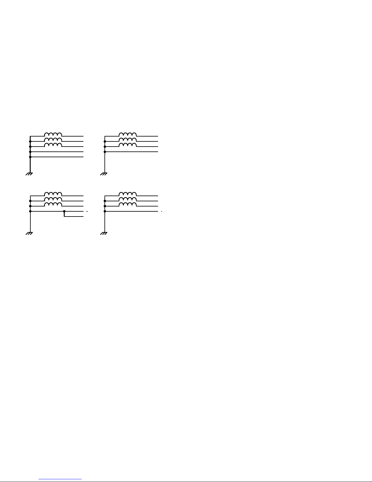
Motor and Circuit Type . . . . . . . . . . . . . . . . . . . . . . . . . . . . . . . . . . . . . . . . . . . 20
Bypass Operation . . . . . . . . . . . . . . . . . . . . . . . . . . . . . . . . . . . . . . . . . . . . . . . . 22
Connecting EX Motors . . . . . . . . . . . . . . . . . . . . . . . . . . . . . . . . . . . . . . . . . . . . 22
PowerXL DG1 Series VFD MN040002EN—March 2014 www.eaton.com iii

PowerXL DG1 Series VFD
Table of Contents, continued
CHAPTER 6—INSTALLATION REQUIREMENTS
Electrical Installation Warnings and Cautions . . . . . . . . . . . . . . . . . . . . . . . . . . 23
Standard Mounting Instructions . . . . . . . . . . . . . . . . . . . . . . . . . . . . . . . . . . . . 23
Dimensions . . . . . . . . . . . . . . . . . . . . . . . . . . . . . . . . . . . . . . . . . . . . . . . . . . . . 25
Standard Drive Mounting . . . . . . . . . . . . . . . . . . . . . . . . . . . . . . . . . . . . . . . . . . 26
Power Wiring Selection . . . . . . . . . . . . . . . . . . . . . . . . . . . . . . . . . . . . . . . . . . . 29
Cable Selection: Power and Motor Leads . . . . . . . . . . . . . . . . . . . . . . . . . . . . . 29
Line (Mains) and Motor Cable Installation . . . . . . . . . . . . . . . . . . . . . . . . . . . . . 29
Connection Tightening Torque . . . . . . . . . . . . . . . . . . . . . . . . . . . . . . . . . . . . . 29
Cable Routing . . . . . . . . . . . . . . . . . . . . . . . . . . . . . . . . . . . . . . . . . . . . . . . . . . 30
Wiring the VFD . . . . . . . . . . . . . . . . . . . . . . . . . . . . . . . . . . . . . . . . . . . . . . . . . 30
Rubber Grommet Installation Instructions . . . . . . . . . . . . . . . . . . . . . . . . . . . . . 32
Control Board . . . . . . . . . . . . . . . . . . . . . . . . . . . . . . . . . . . . . . . . . . . . . . . . . . . 37
Safe Torque Off (STO) . . . . . . . . . . . . . . . . . . . . . . . . . . . . . . . . . . . . . . . . . . . . 38
Connection to Power Section . . . . . . . . . . . . . . . . . . . . . . . . . . . . . . . . . . . . . . 38
Three-Phase Input Connection . . . . . . . . . . . . . . . . . . . . . . . . . . . . . . . . . . . . . 38
Terminal Designations in the Power Section . . . . . . . . . . . . . . . . . . . . . . . . . . . 38
Ground Connection . . . . . . . . . . . . . . . . . . . . . . . . . . . . . . . . . . . . . . . . . . . . . . 39
Product Modified Sticker . . . . . . . . . . . . . . . . . . . . . . . . . . . . . . . . . . . . . . . . . . 39
Checking the Cable and Motor Insulation . . . . . . . . . . . . . . . . . . . . . . . . . . . . . 39
CHAPTER 7—EMC INSTALLATION
EMC Measures in the Control Panel . . . . . . . . . . . . . . . . . . . . . . . . . . . . . . . . . 40
Earthing . . . . . . . . . . . . . . . . . . . . . . . . . . . . . . . . . . . . . . . . . . . . . . . . . . . . . . . 40
Screen Earth Kit . . . . . . . . . . . . . . . . . . . . . . . . . . . . . . . . . . . . . . . . . . . . . . . . . 40
Installation Requirements . . . . . . . . . . . . . . . . . . . . . . . . . . . . . . . . . . . . . . . . . 41
International EMC Protection Cable Requirements . . . . . . . . . . . . . . . . . . . . . . 42
Installation in Corner-Grounded Network . . . . . . . . . . . . . . . . . . . . . . . . . . . . . 43
Installation in IT System . . . . . . . . . . . . . . . . . . . . . . . . . . . . . . . . . . . . . . . . . . . 43
APPENDIX A—TECHNICAL DATA AND SPECIFICATIONS
APPENDIX B—INSTALLATION GUIDELINES
Cable and Fuse Sizing . . . . . . . . . . . . . . . . . . . . . . . . . . . . . . . . . . . . . . . . . . . . 46
Temperature Deratings . . . . . . . . . . . . . . . . . . . . . . . . . . . . . . . . . . . . . . . . . . . 50
Heat Loss Data . . . . . . . . . . . . . . . . . . . . . . . . . . . . . . . . . . . . . . . . . . . . . . . . . 54
Brake Resistor Sizing . . . . . . . . . . . . . . . . . . . . . . . . . . . . . . . . . . . . . . . . . . . . . 54
APPENDIX C—DIMENSION DRAWINGS
APPENDIX D—SAFETY INSTRUCTIONS FOR UL AND CUL
UL Standards Compliance . . . . . . . . . . . . . . . . . . . . . . . . . . . . . . . . . . . . . . . . . 65
Field Wiring . . . . . . . . . . . . . . . . . . . . . . . . . . . . . . . . . . . . . . . . . . . . . . . . . . . . 66
iv PowerXL DG1 Series VFD MN040002EN—March 2014 www.eaton.com

List of Figures
Figure 1. RTC Battery Connection . . . . . . . . . . . . . . . . . . . . . . . . . . . . . . . . . . . . . . . . . 1
Figure 2. Rating Label . . . . . . . . . . . . . . . . . . . . . . . . . . . . . . . . . . . . . . . . . . . . . . . . . . 2
Figure 3. Catalog Numbering System . . . . . . . . . . . . . . . . . . . . . . . . . . . . . . . . . . . . . . 3
Figure 4. Drive System (PDS = Power Drive System) . . . . . . . . . . . . . . . . . . . . . . . . . . 9
Figure 5. AC Power Networks with Grounded Neutral Point (TN- / TT Networks) . . . . . 10
Figure 6. Description of the DG1 Series . . . . . . . . . . . . . . . . . . . . . . . . . . . . . . . . . . . . 12
Figure 7. Block Diagram, Elements of DG1 Frequency Inverters . . . . . . . . . . . . . . . . . . 13
Figure 8. Selection Criteria . . . . . . . . . . . . . . . . . . . . . . . . . . . . . . . . . . . . . . . . . . . . . . . 14
Figure 9. Identification on the FI Circuit Breakers . . . . . . . . . . . . . . . . . . . . . . . . . . . . . 16
Figure 10. EMC Measures . . . . . . . . . . . . . . . . . . . . . . . . . . . . . . . . . . . . . . . . . . . . . . . 18
Figure 11. Parallel Connection . . . . . . . . . . . . . . . . . . . . . . . . . . . . . . . . . . . . . . . . . . . . . 20
Figure 12. Example of a Motor Ratings Plate . . . . . . . . . . . . . . . . . . . . . . . . . . . . . . . . . 20
Figure 13. Star and Delta Circuit Types . . . . . . . . . . . . . . . . . . . . . . . . . . . . . . . . . . . . . 20
Figure 14. V/Hz Characteristic Curve . . . . . . . . . . . . . . . . . . . . . . . . . . . . . . . . . . . . . . . 21
Figure 15. Bypass Motor Control (Example) . . . . . . . . . . . . . . . . . . . . . . . . . . . . . . . . . 22
Figure 16. Mounting Space . . . . . . . . . . . . . . . . . . . . . . . . . . . . . . . . . . . . . . . . . . . . . . 24
Figure 17. Type 1/12 Open Drives . . . . . . . . . . . . . . . . . . . . . . . . . . . . . . . . . . . . . . . . . . 25
Figure 18. Input Power and Motor Cable Stripping Lengths . . . . . . . . . . . . . . . . . . . . . 30
Figure 19. Ground Wiring . . . . . . . . . . . . . . . . . . . . . . . . . . . . . . . . . . . . . . . . . . . . . . . . 33
Figure 20. Terminal Block Layout . . . . . . . . . . . . . . . . . . . . . . . . . . . . . . . . . . . . . . . . . . 35
Figure 21. Basic Internal Control Wiring Diagram . . . . . . . . . . . . . . . . . . . . . . . . . . . . . . 36
Figure 22. DG1 Series Adjustable Frequency Drive . . . . . . . . . . . . . . . . . . . . . . . . . . . . 37
Figure 23. Thermistor STO Wiring Diagram . . . . . . . . . . . . . . . . . . . . . . . . . . . . . . . . . . 38
Figure 24. Connection to Power Section . . . . . . . . . . . . . . . . . . . . . . . . . . . . . . . . . . . . 38
Figure 25. Grounding . . . . . . . . . . . . . . . . . . . . . . . . . . . . . . . . . . . . . . . . . . . . . . . . . . . 39
Figure 26. Product Modified Sticker . . . . . . . . . . . . . . . . . . . . . . . . . . . . . . . . . . . . . . . . 39
Figure 27. EMC-Compliant Setup—460/480 Vac . . . . . . . . . . . . . . . . . . . . . . . . . . . . . . 41
Figure 28. Cable Description . . . . . . . . . . . . . . . . . . . . . . . . . . . . . . . . . . . . . . . . . . . . . 42
Figure 29. Locations of the EMC Screw in
Frame 1, Frame 2, Frame 3 and Frame 4 . . . . . . . . . . . . . . . . . . . . . . . . . . . . . . . . 43
Figure 30. Locations of the EMC Screws in Frame 5 . . . . . . . . . . . . . . . . . . . . . . . . . . . 43
Figure 31. FR1 Dimension Drawing . . . . . . . . . . . . . . . . . . . . . . . . . . . . . . . . . . . . . . . . 55
Figure 32. FR1 Dimension Drawing Flange Mount . . . . . . . . . . . . . . . . . . . . . . . . . . . . 56
Figure 33. FR2 Dimension Drawing . . . . . . . . . . . . . . . . . . . . . . . . . . . . . . . . . . . . . . . . 57
Figure 34. FR2 Dimension Drawing Flange Mount . . . . . . . . . . . . . . . . . . . . . . . . . . . . 58
Figure 35. FR3 Dimension Drawing . . . . . . . . . . . . . . . . . . . . . . . . . . . . . . . . . . . . . . . . 59
Figure 36. FR3 Dimension Drawing Flange Mount . . . . . . . . . . . . . . . . . . . . . . . . . . . . 60
Figure 37. FR4 Dimension Drawing . . . . . . . . . . . . . . . . . . . . . . . . . . . . . . . . . . . . . . . . 61
Figure 38. FR4 Dimension Drawing Flange Mount . . . . . . . . . . . . . . . . . . . . . . . . . . . . 62
Figure 39. FR5 Dimension Drawing . . . . . . . . . . . . . . . . . . . . . . . . . . . . . . . . . . . . . . . . 63
Figure 40. FR5 Dimension Drawing Flange Mount . . . . . . . . . . . . . . . . . . . . . . . . . . . . 64
PowerXL DG1 Series VFD
PowerXL DG1 Series VFD MN040002EN—March 2014 www.eaton.com v

PowerXL DG1 Series VFD
List of Tables
Table 1. Common Abbreviations . . . . . . . . . . . . . . . . . . . . . . . . . . . . . . . . . . . . . . . . . . 1
Table 2. Type 1/IP21 . . . . . . . . . . . . . . . . . . . . . . . . . . . . . . . . . . . . . . . . . . . . . . . . . . . . 4
Table 3. Type 12/IP54 . . . . . . . . . . . . . . . . . . . . . . . . . . . . . . . . . . . . . . . . . . . . . . . . . . . 4
Table 4. Type 1/IP21 . . . . . . . . . . . . . . . . . . . . . . . . . . . . . . . . . . . . . . . . . . . . . . . . . . . . 5
Table 5. Type 12/IP54 . . . . . . . . . . . . . . . . . . . . . . . . . . . . . . . . . . . . . . . . . . . . . . . . . . . 5
Table 6. Frame 1 . . . . . . . . . . . . . . . . . . . . . . . . . . . . . . . . . . . . . . . . . . . . . . . . . . . . . . 6
Table 7. Frame 2 . . . . . . . . . . . . . . . . . . . . . . . . . . . . . . . . . . . . . . . . . . . . . . . . . . . . . . . 6
Table 8. Frame 3 . . . . . . . . . . . . . . . . . . . . . . . . . . . . . . . . . . . . . . . . . . . . . . . . . . . . . . 7
Table 9. Frame 4 . . . . . . . . . . . . . . . . . . . . . . . . . . . . . . . . . . . . . . . . . . . . . . . . . . . . . . 7
Table 10. Frame 5 . . . . . . . . . . . . . . . . . . . . . . . . . . . . . . . . . . . . . . . . . . . . . . . . . . . . . . 8
Table 11. Drive System Components . . . . . . . . . . . . . . . . . . . . . . . . . . . . . . . . . . . . . . . 9
Table 12. Elements of DG1 Frequency Inverters . . . . . . . . . . . . . . . . . . . . . . . . . . . . . . 13
Table 13. Maintenance Measures and Intervals . . . . . . . . . . . . . . . . . . . . . . . . . . . . . . 15
Table 14. Maximum Motor Cable Length by Frame Size
without dV/dT Protected C2 Ratings . . . . . . . . . . . . . . . . . . . . . . . . . . . . . . . . . . . 18
Table 15. Assignment of Frequency Inverters to Example Motor Circuit . . . . . . . . . . . . 21
Table 16. Bypass Motor Control . . . . . . . . . . . . . . . . . . . . . . . . . . . . . . . . . . . . . . . . . . . 22
Table 17. Space Requirements for Mounting the DG1 Series VFD and Airflow . . . . . . . 24
Table 18. Mounting Drive Dimensions . . . . . . . . . . . . . . . . . . . . . . . . . . . . . . . . . . . . . . 25
Table 19. Tightening Torque . . . . . . . . . . . . . . . . . . . . . . . . . . . . . . . . . . . . . . . . . . . . . . 29
Table 20. Spacing Between Parallel Motor Cables . . . . . . . . . . . . . . . . . . . . . . . . . . . . 29
Table 21. Maximum Motor Cable Length by Frame Size
without dV/dT Protected C2 Ratings . . . . . . . . . . . . . . . . . . . . . . . . . . . . . . . . . . . 29
Table 22. Input Power and Motor Cable Stripping and Wire Lengths . . . . . . . . . . . . . . 30
Table 23. I/O Connection . . . . . . . . . . . . . . . . . . . . . . . . . . . . . . . . . . . . . . . . . . . . . . . . 34
Table 24. I/O Specifications . . . . . . . . . . . . . . . . . . . . . . . . . . . . . . . . . . . . . . . . . . . . . . 35
Table 25. 1st Environment 2nd Environment EMC Levels
According to EN 61800-3 (2004) . . . . . . . . . . . . . . . . . . . . . . . . . . . . . . . . . . . . . . . 42
Table 26. Control Wiring Requirements . . . . . . . . . . . . . . . . . . . . . . . . . . . . . . . . . . . . . 42
Table 27. Cable Categories . . . . . . . . . . . . . . . . . . . . . . . . . . . . . . . . . . . . . . . . . . . . . . . 42
Table 28. PowerXL Series—DG1 . . . . . . . . . . . . . . . . . . . . . . . . . . . . . . . . . . . . . . . . . . 44
Table 29. North America Cable and Fuse Sizes—208 Vac to 240 Vac Ratings . . . . . . . . 46
Table 30. International Cable and Fuse Sizes—208 Vac to 240 Vac Ratings . . . . . . . . . 47
Table 31. North America Cable and Fuse Sizes—440 Vac to 500 Vac Ratings . . . . . . . . 48
Table 32. International Cable and Fuse Sizes—380 Vac to 440 Vac Ratings . . . . . . . . . 49
Table 33. 230V Temperature and Switching Frequency Deratings (VT) . . . . . . . . . . . . . 50
Table 34. 230V Temperature and Switching Frequency Deratings (CT) . . . . . . . . . . . . . 51
Table 35. 460V Temperature and Switching Frequency Deratings (VT) . . . . . . . . . . . . . 52
Table 36. 460V Temperature and Switching Frequency Deratings (CT) . . . . . . . . . . . . . 53
Table 37. Heat Loss Data . . . . . . . . . . . . . . . . . . . . . . . . . . . . . . . . . . . . . . . . . . . . . . . . 54
Table 38. Brake Resistor Sizing Data . . . . . . . . . . . . . . . . . . . . . . . . . . . . . . . . . . . . . . . 54
Table 39. Fuse Ratings—400V Drive Series . . . . . . . . . . . . . . . . . . . . . . . . . . . . . . . . . . 65
Table 40. Fuse Ratings—230V Drive Series . . . . . . . . . . . . . . . . . . . . . . . . . . . . . . . . . . 66
Table 41. Required Line and Motor Wire Torque (400V) . . . . . . . . . . . . . . . . . . . . . . . . . 66
Table 42. Required Line and Motor Wire Torque (230V) . . . . . . . . . . . . . . . . . . . . . . . . 67
Table 43. Required Line and Motor Wire Torque (400V) . . . . . . . . . . . . . . . . . . . . . . . . 67
Table 44. Required Line and Motor Wire Torque (230V) . . . . . . . . . . . . . . . . . . . . . . . . 68
vi PowerXL DG1 Series VFD MN040002EN—March 2014 www.eaton.com

Safety
Warning!
Dangerous Electrical Voltage!
Before Commencing the Installation
●
Disconnect the power supply of the device
●
Ensure that devices cannot be accidentally restarted
●
Verify isolation from the supply
●
Earth and short circuit the device
●
Cover or enclose any adjacent live components
●
Only suitably qualified personnel in accordance with
EN 50110-1/-2 (VDE 0105 Part 100) may work on this
device/system
●
Before installation and before touching the device ensure
that you are free of electrostatic charge
●
The functional earth (FE, PES) must be connected to the
protective earth (PE) or the potential equalization. The
system installer is responsible for implementing this
connection
●
Connecting cables and signal lines should be installed so
that inductive or capacitive interference does not impair
the automation functions
●
Install automation devices and related operating elements
in such a way that they are well protected against
unintentional operation
●
Suitable safety hardware and software measures should
be implemented for the I/O interface so that an open
circuit on the signal side does not result in undefined
states in the automation devices
●
Ensure a reliable electrical isolation of the extra-low
voltage of the 24V supply. Only use power supply units
complying with IEC 60364-4-41 (VDE 0100 Part 410) or
HD384.4.41 S2
●
Deviations of the input voltage from the rated value must
not exceed the tolerance limits given in the specifications,
otherwise this may cause malfunction and dangerous
operation
●
Emergency stop devices complying with IEC/EN 60204-1
must be effective in all operating modes of the automation
devices. Unlatching the emergency-stop devices must not
cause a restart
●
Devices that are designed for mounting in housings or
control cabinets must only be operated and controlled after
they have been installed and with the housing closed.
Desktop or portable units must only be operated and
controlled in enclosed housings
PowerXL DG1 Series VFD
●
Measures should be taken to ensure the proper restart of
programs interrupted after a voltage dip or failure. This
should not cause dangerous operating states even for a
short time. If necessary, emergency-stop devices should
be implemented
●
Wherever faults in the automation system may cause
injury or material damage, external measures must be
implemented to ensure a safe operating state in the event
of a fault or malfunction (for example, by means of
separate limit switches, mechanical interlocks, and so on)
●
Depending on their degree of protection, adjustable
frequency drives may contain live bright metal parts,
moving or rotating components, or hot surfaces during and
immediately after operation
●
Removal of the required covers, improper installation, or
incorrect operation of motor or adjustable frequency drive
may cause the failure of the device and may lead to
serious injury or damage
●
The applicable national accident prevention and safety
regulations apply to all work carried out on live adjustable
frequency drives
●
The electrical installation must be carried out in
accordance with the relevant regulations (for example,
with regard to cable cross sections, fuses, PE)
●
Transport, installation, commissioning, and maintenance
work must be carried out only by qualified personnel
(IEC 60364, HD 384 and national occupational safety
regulations)
●
Installations containing adjustable frequency drives must
be provided with additional monitoring and protective
devices in accordance with the applicable safety
regulations. Modifications to the adjustable frequency
drives using the operating software are permitted
●
All covers and doors must be kept closed during operation
●
To reduce hazards for people or equipment, the user must
include in the machine design measures that restrict the
consequences of a malfunction or failure of the drive
(increased motor speed or sudden standstill of motor).
These measures include:
●
Other independent devices for monitoring safety-related
variables (speed, travel, end positions, and so on)
●
Electrical or non-electrical system-wide measures
(electrical or mechanical interlocks)
●
Never touch live parts or cable connections of the
adjustable frequency drive after it has been
disconnected from the power supply. Due to the charge
in the capacitors, these parts may still be live after
disconnection. Fit appropriate warning signs
PowerXL DG1 Series VFD MN040002EN—March 2014 www.eaton.com vii
PowerXL DG1 Series VFD
WARNING
WARNING
WARNING
WARNING
WARNING
WARNING
WARNING
Read this manual thoroughly and make sure you understand
the procedures before you attempt to install, set up, operate
or carry out any maintenance work on this DG1 Adjustable
Frequency Drive.
Definitions and Symbols
WARNING
This symbol indicates high voltage. It calls your attention
to items or operations that could be dangerous to you
and other persons operating this equipment. Read the
message and follow the instructions carefully.
This symbol is the “Safety Alert Symbol.” It occurs with
either of two signal words: CAUTION or WARNING, as
described below.
WARNING
Indicates a potentially hazardous situation which, if not
avoided, can result in serious injury or death.
CAUTION
Indicates a potentially hazardous situation which, if not
avoided, can result in minor to moderate injury, or serious
damage to the product. The situation described in the
CAUTION may, if not avoided, lead to serious results.
Important safety measures are described in CAUTION (as
well as WARNING).
The components in the drive’s power section remain
energized after the supply voltage has been switched off.
After disconnecting the supply, wait at least five minutes
before removing the cover to allow the intermediate
circuit capacitors to discharge.
Pay attention to hazard warnings!
DANGER
5 MIN
Electric shock hazard—risk of injuries! Carry out wiring
work only if the unit is de-energized.
Do not perform any modifications on the AC drive when
it is connected to mains.
Warnings and Cautions
Hazardous High Voltage
WARNING
Motor control equipment and electronic controllers are
connected to hazardous line voltages. When servicing
drives and electronic controllers, there may be exposed
components with housings or protrusions at or above
line potential. Extreme care should be taken to protect
against shock.
●
Stand on an insulating pad and make it a habit to use
only one hand when checking components.
●
Always work with another person in case an
emergency occurs.
●
Disconnect power before checking controllers or
performing maintenance.
●
Be sure equipment is properly earthed.
●
Wear safety glasses whenever working on electronic
controllers or rotating machinery.
Be sure to ground the unit following the instructions in
this manual. Ungrounded units may cause electric shock
and/or fire.
This equipment should only be installed, adjusted, and
serviced by qualified electrical maintenance personnel
familiar with the construction and operation of this type
of equipment and the hazards involved. Failure to
observe this precaution could result in death or severe
injury.
Components within the drive are live when it is
connected to power. Contact with this voltage is
extremely dangerous and may cause death or severe
injury.
Line terminals (L1, L2, L3), motor terminals (U, V, W) and
the DC link/brake resistor terminals (DC–, DC+/R+, R–)
are live when the drive is connected to power, even if the
motor is not running. Contact with this voltage is
extremely dangerous and may cause death or severe
injury.
viii PowerXL DG1 Series VFD MN040002EN—March 2014 www.eaton.com
WARNING
WARNING
WARNING
WARNING
Even though the control I/O-terminals are isolated from
line voltage, the relay outputs and other I/O-terminals
may have dangerous voltage present even when the
drive is disconnected from power. Contact with this
voltage is extremely dangerous and may cause death or
severe injury.
WARNING
This equipment has a large capacitive leakage current
during operation, which can cause enclosure parts to be
above ground potential. Proper grounding, as described
in this manual, is required. Failure to observe this
precaution could result in death or severe injury.
WARNING
Before applying power to this drive, make sure that the
front and cable covers are closed and fastened to prevent
exposure to potential electrical fault conditions. Failure
to observe this precaution could result in death or severe
injury.
WARNING
An upstream disconnect/protective device must be
provided as required by the National Electric Code
(NEC®). Failure to follow this precaution may result in
death or severe injury.
WARNING
This drive can cause a DC current in the protective
earthing conductor. Where a residual current-operated
protective (RCD) or monitoring (RCM) device is used for
protection in case of direct or indirect contact, only an
RCD or RCM of Type B is allowed on the supply side of
this product.
PowerXL DG1 Series VFD
Before opening the drive covers:
●
Disconnect all power to the drive, including external
control power that may be present.
●
Wait a minimum of five minutes after all the lights on
the keypad are off. This allows time for the DC bus
capacitors to discharge.
●
A hazard voltage may still remain in the DC bus
capacitors even if the power has been turned off.
Confirm that the capacitors have fully discharged by
measuring their voltage using a multimeter set to
measure the DC voltage.
Failure to follow these precautions may cause death or
severe injury.
The opening of the branch-circuit protective device may
be an indication that a fault current has been interrupted.
To reduce the risk of fire or electric shock, current-carrying
parts and other components of the controller should
be examined and replaced if damaged. If burnout of the
current element of an overload relay occurs, the complete
overload relay must be replaced.
®
Operation of this equipment requires detailed
installation and operation instructions provided in the
Installation/Operation manual intended for use with this
product. This information is provided on the CD-ROM,
floppy diskette(s) or other storage device included in the
container this device was packaged in. it should be
retained with this device at all times. A hard copy of this
information may be ordered from Eaton literature
fulfillment.
WARNING
Carry out wiring work only after the drive has been
correctly mounted and secured.
PowerXL DG1 Series VFD MN040002EN—March 2014 www.eaton.com ix
PowerXL DG1 Series VFD
CAUTION
CAUTION
CAUTION
CAUTION
CAUTION
CAUTION
WARNING
Before servicing the drive:
●
Disconnect all power to the drive, including external
control power that may be present.
●
Place a “DO NOT TURN ON” label on the disconnect
device.
●
Lock the disconnect device in the open position.
Failure to follow these instructions will result in death or
serious injury.
WARNING
The drive outputs (U, V, W) must not be connected to the
input voltage or the utility line power as severe damage
to the device may occur and there may be a risk of fire.
Install this drive in a well-ventilated room that is not subject
to temperature extremes, high humidity, or condensation,
and avoid locations that are directly exposed to sunlight, or
have high concentrations of dust, corrosive gas, explosive
gas, inflammable gas, grinding fluid mist, etc. Improper
installation may result in a fire hazard.
When selecting the cable cross-section, take the voltage
drop under load conditions into account. The consideration of
other standards is the responsibility of the user.
The user is responsible for compliance with all international
and national electrical standards in force concerning
protective grounding of all equipment.
WARNING
The heat sink and/or outer enclosure may reach a high
temperature.
Pay attention to hazard warnings!
Hot Surface—Risk of Burn. DO NOT TOUCH!
CAUTION
Any electrical or mechanical modification to this drive without
prior written consent of Eaton will void all warranties and may
result in a safety hazard in addition and voiding of the UL
listing.
CAUTION
Install this drive on flame-resistant material such as a steel
plate to reduce the risk of fire.
CAUTION
Install this drive on a perpendicular surface that is able to
support the weight of the drive and is not subject to
vibration, to lessen the risk of the drive falling and being
damaged and/or causing personal injury.
CAUTION
Prevent foreign material such as wire clippings or metal
shavings from entering the drive enclosure, as this may
cause arcing damage and fire.
The specified minimum PE conductor cross-sections in this
manual must be maintained.
Touch current in this equipment exceeds 3.5 mA (AC). The
minimum size of the protective earthing conductor shall
comply with the requirements of EN 61800-5-1 and/or the
local safety regulations.
Touch currents in this frequency inverter are greater than
3.5 mA (AC). According to product standard IEC/EN
61800-5-1, an additional equipment grounding conductor of
the same cross-sectional area as the original protective
earthing conductor must be connected, or the cross-section
®
of the equipment grounding conductor must be at least
2
10 mm
be used.
Debounced inputs may not be used in the safety circuit
diagram. Residual current circuit breakers (RCD) are only to
be installed between the AC power supply network and the
drive.
Debounced inputs may not be used in the safety circuit
diagram. If you are connecting multiple motors on one drive,
you must design the contactors for the individual motors
according to utilization category AC-3.
Selecting the motor contactor is done according to the rated
operational current of the motor to be connected.
Cu. Drive requires that only copper conductor should
x PowerXL DG1 Series VFD MN040002EN—March 2014 www.eaton.com
CAUTION
CAUTION
CAUTION
CAUTION
CAUTION
CAUTION
CAUTION
CAUTION
CAUTION
CAUTION
Debounced inputs may not be used in the safety circuit
diagram. A changeover between the drive and the input
supply must take place in a voltage-free state.
PowerXL DG1 Series VFD
Do not touch any components on the circuit boards. Static
voltage discharge may damage the components.
CAUTION
Debounced inputs may not be used in the safety circuit
diagram. Fire hazard!
Only use cables, protective switches, and contactors that
feature the indicated permissible nominal current value.
CAUTION
Before connecting the drive to AC mains make sure that the
EMC protection class settings of the drive are appropriately
made according to instructions in this manual.
●
If the drive is to be used in a floating distribution network,
remove screws at MOV and EMC. See “Installation in
Corner-Grounded Network” on Page 43 and “Installation in
IT System” on Page 43 respectively.
●
Disconnect the internal EMC filter when installing the drive
on an IT system (an ungrounded power system or a
high-resistance-grounded [over 30 ohm] power system),
otherwise the system will be connected to ground
potential through the EMC filter capacitors. This may
cause danger, or damage the drive.
●
Disconnect the internal EMC filter when installing the drive
on a corner grounded TN system, otherwise the drive will
be damaged.
Note: When the internal EMC filter is disconnected, the
drive might be not EMC compatible.
Before starting the motor, check that the motor is mounted
properly and aligned with the driven equipment. Ensure that
starting the motor will not cause personal injury or damage
equipment connected to the motor.
Set the maximum motor speed (frequency) in the drive
according to the requirements of the motor and the
equipment connected to it. Incorrect maximum frequency
settings can cause motor or equipment damage and personal
injury.
Before reversing the motor rotation direction, ensure that
this will not cause personal injury or equipment damage.
Make sure that no power correction capacitors are
connected to the drive output or the motor terminals to
prevent drive malfunction and potential damage.
Make sure that the drive output terminals (U, V, W) are not
connected to the utility line power as severe damage to the
drive may occur.
●
Do not attempt to install or remove the MOV or EMC
screws while power is applied to the drive’s input
terminals.
Motor and Equipment Safety
CAUTION
Do not perform any meggar or voltage withstand tests on
any part of the drive or its components. Improper testing may
result in damage.
CAUTION
Prior to any tests or measurements of the motor or the
motor cable, disconnect the motor cable at the drive output
terminals (U, V, W) to avoid damaging the drive during motor
or cable testing.
PowerXL DG1 Series VFD MN040002EN—March 2014 www.eaton.com xi
When the control terminals of two or more drive units are
connected in parallel, the auxiliary voltage for these control
connections must be taken from a single source which can
either be one of the units or an external supply.
The drive will start up automatically after an input voltage
interruption if the external run command is on.
Do not control the motor with the disconnecting device
(disconnecting means); instead, use the control panel start
and stop keys and, or commands via the I/O board of the
drive. The maximum allowed number of charging cycles of
the DC capacitors (i.e. power-ups by applying power) is five in
ten minutes.

PowerXL DG1 Series VFD
CAUTION
Improper drive operation:
●
If the drive is not turned on for a long period, the
performance of its electrolytic capacitors will be reduced.
●
If it is stopped for a prolonged period, turn the drive on at
least every six months for at least 5 hours to restore the
performance of the capacitors, and then check its
operation. It is recommended that the drive is not
connected directly to the line voltage. The voltage should
be increased gradually using an adjustable AC source.
Failure to follow these instructions can result in injury
and/or equipment damage.
For more technical information, contact the factory or your
local Eaton sales representative.
xii PowerXL DG1 Series VFD MN040002EN—March 2014 www.eaton.com
Chapter 1—DG1 Series Overview
Chapter 1—DG1 Series Overview
This chapter describes the purpose and contents of this
manual, the receiving inspection recommendations and the
DG1 Series Open Drive catalog numbering system.
How to Use this Manual
The purpose of this manual is to provide you with information
necessary to install, set and customize parameters, start up,
troubleshoot and maintain the Eaton DG1 Series adjustable
frequency drive (AFD). To provide for safe installation and
operation of the equipment, read the safety guidelines at the
beginning of this manual and follow the procedures outlined
in the following chapters before connecting power to the
DG1 Series AFD. Keep this operating manual handy and
distribute to all users, technicians and maintenance
personnel for reference.
Receiving and Inspection
The DG1 Series AFD has met a stringent series of factory
quality requirements before shipment. It is possible that
packaging or equipment damage may have occurred during
shipment. After receiving your DG1 Series AFD, please
check for the following:
Check to make sure that the package includes the Instruction
Leaflet (IL040016EN), Quick Start Guide (MN040006EN),
User Manual CD (CD040002EN) and accessory packet. The
accessory packet includes:
●
Rubber grommets
●
Control cable grounding clamps
●
Additional grounding screw
Inspect the unit to ensure it was not damaged during
shipment.
Make sure that the part number indicated on the nameplate
corresponds with the catalog number on your order.
If shipping damage has occurred, please contact and file a
claim with the carrier involved immediately.
If the delivery does not correspond to your order, please
contact your Eaton Electrical representative.
Note: Do not destroy the packing. The template printed
on the protective cardboard can be used for marking
the mounting points of the DG1 AFD on the wall or
in a cabinet.
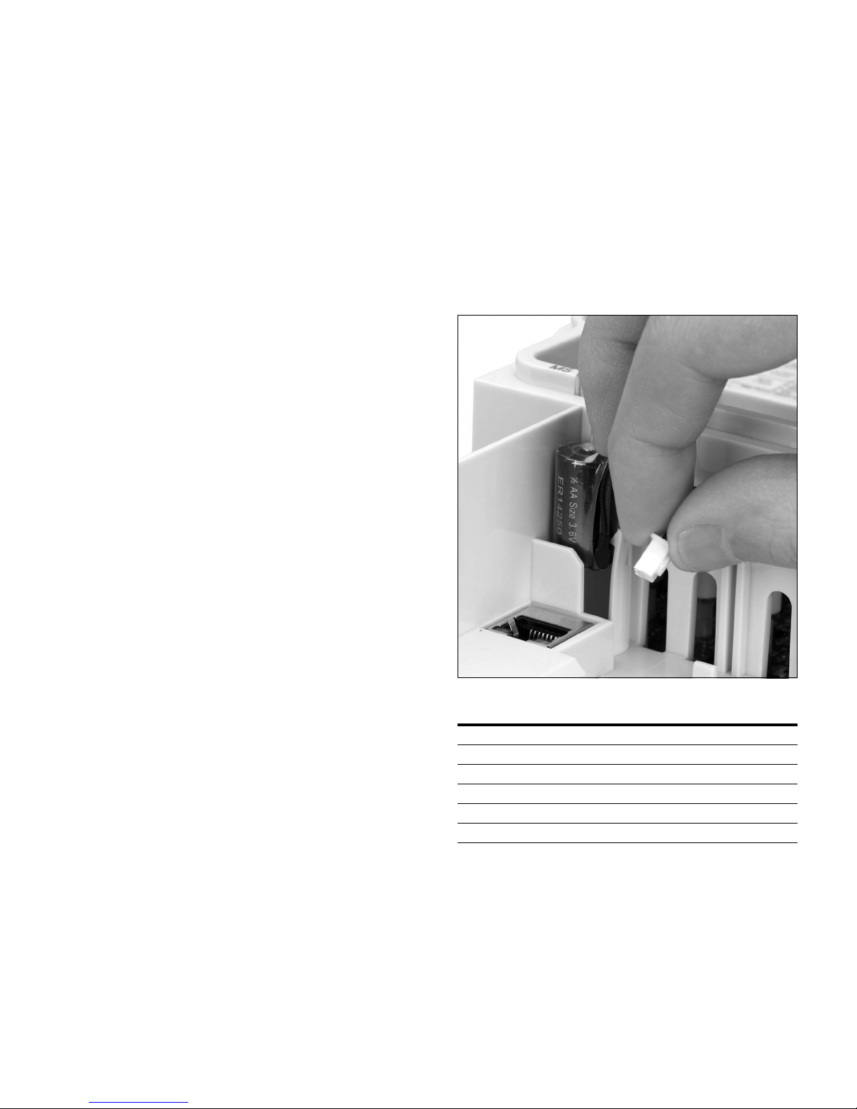
Real Time Clock Battery Activation
To activate the real time clock (RTC) functionality in the
PowerXL DG1 Series AFD, the RTC battery (already mounted
in the drive) must be connected to the control board.
Simply remove the primary drive cover, locate the RTC
battery directly below the keypad, and connect the white
2-wire connector to the receptacle on the control board.
Figure 1. RTC Battery Connection
Table 1. Common Abbreviations
Abbreviation Definition
CT Constant torque with high overload rating (150%)
VT Variable torque with low overload rating (110%)
I
H
I
L
AFD Adjustable Frequency Drive
VFD Variable Frequency Drive
High Overload (150%)
Low Overload (110%)
DG1 Series VFD MN040002EN—March 2014 www.eaton.com 1
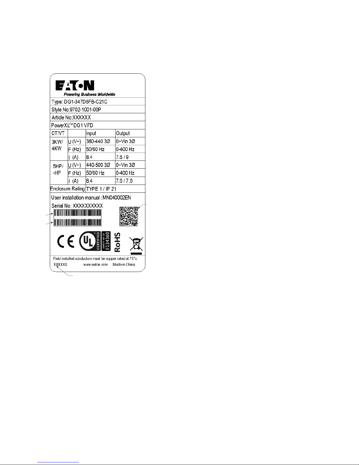
Chapter 1—DG1 Series Overview
Contains
SN, PN,
Type, Date
Contains
EAN Code
Date Code: 20131118
Contains
NAED Code
Rating Label
Figure 2. Rating Label
Carton Labels (U.S. and Europe)
Same as rating label shown above.
2 DG1 Series VFD MN040002EN—March 2014 www.eaton.com

Catalog Number System
Internal Brake Chopper
N = No brake chopper
B = Brake chopper
Series Power Part Options
D G1 –34 4D8 F B –C21 C
Input/Output Voltage Rating
2 = 230V (208–240V, –15%, +10%)
4 = 400V (380–500V, –15%, +10%)
5 = 575V (525–600V, –15%, +10%)
Basic Naming
D = Drive
Output Current Rating (CT)
208–240V 380–500V 525–600V
3D7 = 3.7A, 0.55 kW, 0.75 hp
4D8 = 4.8A, 0.75 kW, 1 hp
6D6 = 6.6A, 1.1 kW, 1.5 hp
7D8 = 7.8A, 1.5 kW, 2 hp
011 = 11A, 2.2 kW, 3 hp
012 = 12.5A, 3 kW, 5 hp (VT)
017 = 17.5A, 3.7 kW, 5 hp
025 = 25A, 5.5 kW, 7.5 hp
031 = 31A, 7.5 kW, 10 hp
048 = 48A, 11 kW, 15 hp
061 = 61A, 15 kW, 20 hp
075 = 75A, 18.5 kW, 25 hp
088 = 88A, 22 kW, 30 hp
114 = 114A, 30 kW, 40 hp
143 = 143A, 37 kW, 50 hp
170 = 170A, 45 kW, 60 hp
211 = 211A, 55 kW, 75 hp
261 = 261A, 75 kW, 100 hp
2D2 = 2.2A, 0.75 kW, 1 hp
3D3 = 3.3A, 1.1 kW, 1.5 hp
4D3 = 4.3A, 1.5 kW, 2 hp
5D6 = 5.6A, 2.2 kW, 3 hp
7D6 = 7.6A, 3 kW, 5 hp
9D0 = 9A, 4 kW, 7.5 hp (VT)
012 = 12A, 5.5 kW, 7.5 hp
016 = 16A, 7.5 kW, 10 hp
023 = 23A, 11 kW, 15 hp
031 = 31A, 15 kW, 20 hp
038 = 38A, 18 kW, 25 hp
046 = 46A, 22 kW, 30 hp
061 = 61A, 30 kW, 40 hp
072 = 72A, 37 kW, 50 hp
087 = 87A, 45 kW, 60 hp
105 = 105A, 55 kW, 75 hp
140 = 140A, 75 kW, 100 hp
170 = 170A, 90 kW, 125 hp
205 = 205A, 110 kW, 150 hp
261 = 261A, 132 kW, 200 hp
3D3 = 3.3A, 1.5 kW, 2 hp
4D5 = 4.5A, 2.2 kW, 3 hp
7D5 = 7.5A, 3.7 kW, 5 hp
010 = 10A, 5.5 kW, 7.5 hp
013 = 13.5A, 7.5 kW, 10 hp
018 = 18A, 11 kW, 15 hp
022 = 22A, 15 kW, 20 hp
027 = 27A, 18 kW, 25 hp
034 = 34A, 22 kW, 30 hp
041 = 41A, 30 kW, 40 hp
052 = 52A, 37 kW, 50 hp
062 = 62A, 45 kW, 60 hp
080 = 80A, 55 kW, 75 hp
100 = 100A, 75 kW, 100 hp
125 = 125A, 90 kW, 125 hp
144 = 144A, 110 kW, 150 hp
208 = 208A, 160 kW, 200 hp
Series
G1 = General purpose
Phase Reference
3 = 3~ INPUT/3~ OUTPUT
Internal EMC Filter
F = Internal EMC filter
Coating of Boards
C = Coated
Enclosure (IP Rating)
21 = IP21/Type 1
54 = IP54/Type 12
Display Option
C = LCD (graphical)
Figure 3. Catalog Numbering System
Chapter 1—DG1 Series Overview
DG1 Series VFD MN040002EN—March 2014 www.eaton.com 3

Chapter 1—DG1 Series Overview
Power Ratings and Product Selection
DG1 Series Drives—208–240 Volt
Table 2. Type 1/IP21
Frame Size
kW Rating (CT/IH)
FR1 0.55 0.75 0.75 1 3.7 4.8 DG1-323D7FB-C21C
0.75 1.1 1 1.5 4.8 6.6 DG1-324D8FB-C21C
1.1 1.5 1.5 2 6.6 7.8 DG1-326D6FB-C21C
1.5 2.2 2 3 7.8 11 DG1-327D8FB-C21C
2.2 3 3 — 11 12.5 DG1-32011FB-C21C
FR2 3 3.7 — 5 12.5 17.5 DG1-32012FB-C21C
3.7 5.5 5 7.5 17.5 25 DG1-32017FB-C21C
5.5 7.5 7.5 10 25 31 DG1-32025FB-C21C
FR37.5 11 10153148DG1-32031FB-C21C
11 15 15 20 48 61 DG1-32048FB-C21C
FR415 18.5 20256175DG1-32061FN-C21C
18.5 22 25307588DG1-32075FN-C21C
22 30 30 40 88 114 DG1-32088FN-C21C
FR5 30 37 40 50 114 143 DG1-32114FN-C21C
37 45 50 60 143 170 DG1-32143FN-C21C
45 55 60 75 170 211 DG1-32170FN-C21C
230V, 50 Hz
FR6
1
55 75 75 100 211 261 DG1-32211FN-C21C
75 90 100 125 261 312 DG1-32261FN-C21C
230V, 50 Hz
kW Rating (VT/IL)
230V, 60 Hz
hp (CT/IH)
230V, 60 Hz
hp (VT/IL)
Current
A (CT/IH)
Current
A (VT/IL) Catalog Number
Table 3. Type 12/IP54
Frame Size
230V, 50 Hz
kW Rating (CT/I
230V, 50 Hz
)
kW Rating (VT/IL)
H
230V, 60 Hz
hp (CT/IH)
230V, 60 Hz
hp (VT/IL)
Current
A (CT/IH)
Current
A (VT/IL) Catalog Number
FR1 0.55 0.75 0.75 1 3.7 4.8 DG1-323D7FB-C54C
0.75 1.1 1 1.5 4.8 6.6 DG1-324D8FB-C54C
1.1 1.5 1.5 2 6.6 7.8 DG1-326D6FB-C54C
1.5 2.2 2 3 7.8 11 DG1-327D8FB-C54C
2.2 3 3 — 11 12.5 DG1-32011FB-C54C
FR2 3 3.7 — 5 12.5 17.5 DG1-32012FB-C54C
3.7 5.5 5 7.5 17.5 25 DG1-32017FB-C54C
5.5 7.5 7.5 10 25 31 DG1-32025FB-C54C
FR37.5 11 10153148DG1-32031FB-C54C
11 15 15 20 48 61 DG1-32048FB-C54C
FR415 18.5 20256175DG1-32061FN-C54C
18.5 22 25307588DG1-32075FN-C54C
22 30 30 40 88 114 DG1-32088FN-C54C
FR5 30 37 40 50 114 143 DG1-32114FN-C54C
37 45 50 60 143 170 DG1-32143FN-C54C
45 55 60 75 170 211 DG1-32170FN-C54C
FR6
1
55 75 75 100 211 261 DG1-32211FN-C54C
75 90 100 125 261 312 DG1-32261FN-C54C
Note
1
FR6 available in 2015.
4 DG1 Series VFD MN040002EN—March 2014 www.eaton.com

Chapter 1—DG1 Series Overview
DG1 Series Drives—380–500 Volt
Table 4. Type 1/IP21
Frame Size
kW Rating (CT/IH)
FR1 0.75 1.1 1 1.5 2.2 3.3 DG1-342D2FB-C21C
1.1 1.5 1.5 2 3.3 4.3 DG1-343D3FB-C21C
1.5 2.2 2 3 4.3 5.6 DG1-344D3FB-C21C
2.2 3 3 5 5.6 7.6 DG1-345D6FB-C21C
345—7.69DG1-347D6FB-C21C
4 5.5 — 7.5 9 12 DG1-349D0FB-C21C
FR2 5.5 7.5 7.5 10 12 16 DG1-34012FB-C21C
7.5 11 10151623DG1-34016FB-C21C
11 15 15 20 23 31 DG1-34023FB-C21C
FR315 18.5 20253138DG1-34031FB-C21C
18.5 22 25303846DG1-34038FB-C21C
22 30 30 40 46 61 DG1-34046FB-C21C
FR430 37 40506172DG1-34061FN-C21C
37 45 50 60 72 87 DG1-34072FN-C21C
45 55 60 75 87 105 DG1-34087FN-C21C
FR5 55 75 75 100 105 140 DG1-34105FN-C21C
75 90 100 125 140 170 DG1-34140FN-C21C
90 110 125 150 170 205 DG1-34170FN-C21C
400V, 50 Hz
1
FR6
110 132 150 200 205 261 DG1-34205FN-C21C
132 160 200 250 261 310 DG1-34261FN-C21C
400V, 50 Hz
kW Rating (VT/IL)
460V, 60 Hz
hp (CT/IH)
460V, 60 Hz
hp (VT/IL)
Current
A (CT/IH)
Current
A (VT/IL) Catalog Number
Table 5. Type 12/IP54
Frame Size
400V, 50 Hz
kW Rating (CT/I
400V, 50 Hz
)
kW Rating (VT/IL)
H
460V, 60 Hz
hp (CT/IH)
460V, 60 Hz
hp (VT/IL)
Current
A (CT/IH)
Current
A (VT/IL) Catalog Number
FR1 0.75 1.1 1 1.5 2.2 3.3 DG1-342D2FB-C54C
1.1 1.5 1.5 2 3.3 4.3 DG1-343D3FB-C54C
1.5 2.2 2 3 4.3 5.6 DG1-344D3FB-C54C
2.2 3 3 5 5.6 7.6 DG1-345D6FB-C54C
345—7.69DG1-347D6FB-C54C
4 5.5 — 7.5 9 12 DG1-349D0FB-C54C
FR2 5.5 7.5 7.5 10 12 16 DG1-34012FB-C54C
7.5 11 10151623DG1-34016FB-C54C
11 15 15 20 23 31 DG1-34023FB-C54C
FR315 18.5 20253138DG1-34031FB-C54C
18.5 22 25303846DG1-34038FB-C54C
22 30 30 40 46 61 DG1-34046FB-C54C
FR430 37 40506172DG1-34061FN-C54C
37 45 50 60 72 87 DG1-34072FN-C54C
45 55 60 75 87 105 DG1-34087FN-C54C
FR5 55 75 75 100 105 140 DG1-34105FN-C54C
75 90 100 125 140 170 DG1-34140FN-C54C
90 110 125 150 170 205 DG1-34170FN-C54C
1
FR6
110 132 150 200 205 261 DG1-34205FN-C54C
132 160 200 250 261 310 DG1-34261FN-C54C
Note
1
FR6 available in 2015.
DG1 Series VFD MN040002EN—March 2014 www.eaton.com 5

Chapter 1—DG1 Series Overview
Replacement Parts
Table 6. Frame 1
Catalog Number Catalog Number Catalog Number
Description 230V 480V 575V
Standard keypad
Main control board
Control board cover DXG-SPR-BCOVER DXG-SPR-BCOVER DXG-SPR-BCOVER
Type 1/IP21 standard cover DXG-SPR-FR1CVR DXG-SPR-FR1CVR
Main fan kit
Control fan DXG-SPR-2FR1CF DXG-SPR-4FR1CF
Main power board DXG-SPR-2FR1MPB DXG-SPR-4FR1MPB
EMI board DXG-SPR-2FR1EB DXG-SPR-4FR1EB
Middle chassis cover DXG-SPR-FR1MCC DXG-SPR-FR1MCC
Outer housing DXG-SPR-FR1OH DXG-SPR-FR1OH
UL conduit plate DXG-SPR-FR1CPUL DXG-SPR-FR1CPUL
IEC conduit plate DXG-SPR-FR1CPIEC DXG-SPR-FR1CPIEC
Notes
1
Factory recommended spare parts.
2
575V available in 2015.
1
1
1
DXG-KEY-LCD DXG-KEY-LCD DXG-KEY-LCD
DXG-SPR-CTRLBOARD DXG-SPR-CTRLBOARD DXG-SPR-CTRLBOARD
2
DXG-SPR-FR1FAN DXG-SPR-FR1FAN
2
2
2
2
2
2
2
2
Table 7. Frame 2
Catalog Number Catalog Number Catalog Number
Description 230V 480V 575V
Standard keypad
Main control board
1
1
DXG-KEY-LCD DXG-KEY-LCD DXG-KEY-LCD
DXG-SPR-CTRLBOARD DXG-SPR-CTRLBOARD DXG-SPR-CTRLBOARD
Control board cover DXG-SPR-BCOVER DXG-SPR-BCOVER DXG-SPR-BCOVER
2
Type 1/IP21 standard cover DXG-SPR-FR2CVR DXG-SPR-FR2CVR
Main fan kit
1
DXG-SPR-FR2FAN DXG-SPR-FR2FAN
Control fan DXG-SPR-FR2CF DXG-SPR-FR2CF
Bus capacitor DXG-SPR-2FR2BC DXG-SPR-4FR24BC
Main power board DXG-SPR-2FR2MPB DXG-SPR-4FR2MPB
EMI board DXG-SPR-2FR2EB DXG-SPR-4FR2EB
IGBT module DXG-SPR-FR2IGBT DXG-SPR-FR2IGBT
Middle chassis cover DXG-SPR-FR2MCC DXG-SPR-FR2MCC
Outer housing DXG-SPR-FR2OH DXG-SPR-FR2OH
UL conduit plate DXG-SPR-FR2CPUL DXG-SPR-FR2CPUL
IEC conduit plate DXG-SPR-FR2CPIEC DXG-SPR-FR2CPIEC
Notes
1
Factory recommended spare parts.
2
575V available in 2015.
2
2
2
2
2
2
2
2
2
2
6 DG1 Series VFD MN040002EN—March 2014 www.eaton.com

Chapter 1—DG1 Series Overview
Table 8. Frame 3
Catalog Number Catalog Number Catalog Number
Description 230V 480V 575V
Standard keypad
Main control board
Control board cover DXG-SPR-BCOVER DXG-SPR-BCOVER DXG-SPR-BCOVER
Type 1/IP21 standard cover DXG-SPR-FR3CVR DXG-SPR-FR3CVR
Main fan kit
Control fan DXG-SPR-FR34CF DXG-SPR-FR34CF
Bus capacitor DXG-SPR-FR3BC DXG-SPR-FR3BC
Main power board DXG-SPR-2FR3MPB DXG-SPR-4FR3MPB
EMI board DXG-SPR-2FR3EB DXG-SPR-4FR3EB
Drive board DXG-SPR-2FR3DB DXG-SPR-4FR3DB
Output board DXG-SPR-FR3OB DXG-SPR-FR3OB
Middle chassis cover DXG-SPR-FR3MCC DXG-SPR-FR3MCC
Outer housing DXG-SPR-FR3OH DXG-SPR-FR3OH
UL conduit plate DXG-SPR-FR3CPUL DXG-SPR-FR3CPUL
IEC conduit plate DXG-SPR-FR3CPIEC DXG-SPR-FR3CPIEC
Notes
1
Factory recommended spare parts.
2
575V available in 2015.
1
1
1
DXG-KEY-LCD DXG-KEY-LCD DXG-KEY-LCD
DXG-SPR-CTRLBOARD DXG-SPR-CTRLBOARD DXG-SPR-CTRLBOARD
2
DXG-SPR-FR3FAN DXG-SPR-FR3FAN
2
2
2
2
2
2
2
2
2
2
2
Table 9. Frame 4
Catalog Number Catalog Number Catalog Number
Description 230V 480V 575V
Standard keypad
Main control board
1
1
DXG-KEY-LCD DXG-KEY-LCD DXG-KEY-LCD
DXG-SPR-CTRLBOARD DXG-SPR-CTRLBOARD DXG-SPR-CTRLBOARD
Control board cover DXG-SPR-BCOVER DXG-SPR-BCOVER DXG-SPR-BCOVER
2
Type 1/IP21 standard cover DXG-SPR-FR4CVR DXG-SPR-FR4CVR
Main fan kit
1
DXG-SPR-FR4FAN DXG-SPR-FR4FAN
Control fan DXG-SPR-FR34CF DXG-SPR-FR34CF
Bus capacitor DXG-SPR-2FR4BC DXG-SPR-4FR24BC
Main power board DXG-SPR-2FR4MPB DXG-SPR-4FR4MPB
EMI board DXG-SPR-2FR4EB DXG-SPR-4FR4EB
Softstart board DXG-SPR-2FR4SB DXG-SPR-4FR4SB
IGBT module DXG-SPR-2FR4IGBT DXG-SPR-4FR4IGBT
Rectifier module DXG-SPR-2FR4RM DXG-SPR-4FR4RM
Brake chopper module DXG-SPR-2FR4BCM DXG-SPR-4FR4BCM
Middle chassis cover DXG-SPR-FR4MCC DXG-SPR-FR4MCC
Outer housing DXG-SPR-FR4OH DXG-SPR-FR4OH
UL conduit plate DXG-SPR-FR4CPUL DXG-SPR-FR4CPUL
IEC conduit plate DXG-SPR-FR4CPIEC DXG-SPR-FR4CPIEC
Notes
1
Factory recommended spare parts.
2
575V available in 2015.
2
2
2
2
2
2
2
2
2
2
2
2
2
DG1 Series VFD MN040002EN—March 2014 www.eaton.com 7

Chapter 1—DG1 Series Overview
Table 10. Frame 5
Catalog Number Catalog Number Catalog Number
Description 230V 480V 575V
Standard keypad
Main control board
Control board cover DXG-SPR-BCOVER DXG-SPR-BCOVER DXG-SPR-BCOVER
Type 1/IP21 standard cover DXG-SPR-FR5CVR DXG-SPR-FR5CVR
Main fan kit
Control fan DXG-SPR-FR5CF DXG-SPR-FR5CF
Bus capacitor DXG-SPR-FR5BC DXG-SPR-FR5BC
Main power board DXG-SPR-2FR5MPB DXG-SPR-4FR5MPB
EMI-1 board DXG-SPR-2FR5E1B DXG-SPR-4FR5E1B
EMI-2 board DXG-SPR-2FR5E2B DXG-SPR-4FR5E2B
EMI-3 board DXG-SPR-FR5E3B DXG-SPR-FR5E3B
IGBT module DXG-SPR-FR5IGBT DXG-SPR-FR5IGBT
Rectifier module DXG-SPR-2FR5RM DXG-SPR-4FR5RM
Brake chopper module DXG-SPR-2FR5BCM DXG-SPR-4FR5BCM
Middle chassis cover DXG-SPR-FR5MCC DXG-SPR-FR5MCC
Outer housing DXG-SPR-FR5OH DXG-SPR-FR5OH
UL conduit plate DXG-SPR-FR5CPUL DXG-SPR-FR5CPUL
IEC conduit plate DXG-SPR-FR5IECCP DXG-SPR-FR5IECCP
Notes
1
Factory recommended spare parts.
2
575V available in 2015.
1
1
1
DXG-KEY-LCD DXG-KEY-LCD DXG-KEY-LCD
DXG-SPR-CTRLBOARD DXG-SPR-CTRLBOARD DXG-SPR-CTRLBOARD
2
DXG-SPR-FR5FAN DXG-SPR-FR5FAN
2
2
2
2
2
2
2
2
2
2
2
2
2
2
8 DG1 Series VFD MN040002EN—March 2014 www.eaton.com
Chapter 2—Engineering Considerations
RCD
PE L1 L2 L3
PE U V W
M
L1
L2
L3
PE
PES
#
CPU
78
Chapter 2—Engineering Considerations
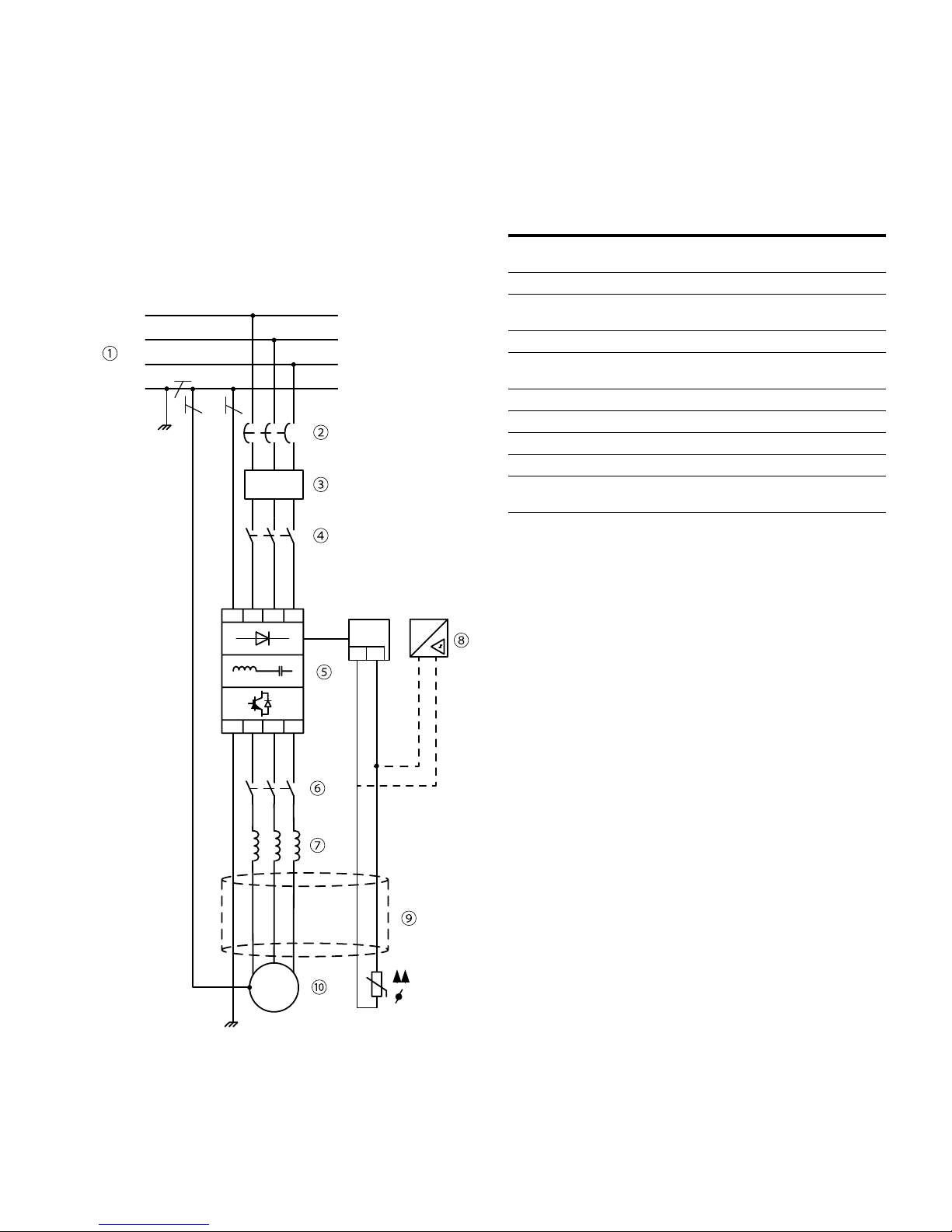
Introduction
This chapter describes the most important features in the
energy circuit of a drive system that you should take into
consideration in your project planning.
Figure 4. Drive System (PDS = Power Drive System)
Table 11. Drive System Components
Item No. Description
1 Power grid configuration, input voltage, input frequency,
interactions with PF correction systems
2 Breakers, fuses, cable cross-sections
3 Protection of persons and animals with residual-current
protective devices
4 Input contactor, disconnector
5 Frequency inverter: mounting, installation; power connection;
EMC measures; circuit examples
6 Output contactor, disconnector
7 Output reactor, dV/dT filter, sine-wave filter
8 Motor protection; thermistor (can be connected to drive directly)
9 Cable lengths, motor cables, shielding (EMC)
10 Motor and application, parallel operation of multiple motors on
a VFD, bypass circuit, DC braking
DG1 Series VFD MN040002EN—March 2014 www.eaton.com 9
Chapter 2—Engineering Considerations
L1
L2
L3
N
TT
L1
L2
L3
N
PE
TN-C-S
L1
L2
L3
N
PE
TN-S
L1
L2
L3
PEN
TN-C
Electrical Power Network
Input Connection and Configuration
The DG1 Series frequency inverters can be connected and
operated with all control-point grounded AC power networks
(see IEC 60364 for more information).
Figure 5. AC Power Networks with Grounded Neutral
Point (TN- / TT Networks)
Input Voltage and Frequency
The standardized input voltages (IEC 60038, VDE017-1) for
energy suppliers (EVU) guarantee the following conditions at
the transition points:
●
Deviation from the rated value of voltage: Max. ±10%
●
Deviation in voltage phase balance: Max. ±3%
●
Deviation from rated value of the frequency: Max. ±4%
The board tolerance band of the DG1 frequency
inverter considers the rated value for European as
(EU: ULN = 230V / 400V, 50 Hz) and American as
(USA: U
●
●
For the bottom voltage value, the permitted voltage drop of
4% in the consumer circuits is also taken into account,
therefore a total of ULN –14%.
●
●
The permitted frequency range is 50/60 Hz (45 Hz –0% to
66 Hz +0%).
LN = 240V / 480V, 60 Hz) standard voltages:
230V, 50 Hz (EU) and 240V, 60 Hz (USA) at DG1-32_
400V, 50 Hz (EU) and 480V, 60 Hz (USA) at DG1-34_
230V device class (DG1-32_): 208V –15% to 240V +10%
(177V –0% to 264V +0%)
400V device class (DG1-34_): 380V –15% to 500V +10%
(323V –0% to 550V +0%)
The frequency inverter can be applied to all types of power
networks above. If multiple frequency inverters with
single-phase supplies are to be connected, a symmetrical
distribution to the three external conductors shall be taken
into account. In addition, the total current of all single-phase
consumers is not to cause an overload of the neutral
conductor (N-conductor).
The connection and operation of frequency inverters to
asymmetrically grounded TN networks (phase-grounded
delta network “Grounded Delta”, USA) or neutral point
ungrounded or high-resistance grounded (>30 ohms) IT
networks is only conditionally permissible. In these networks
above-mentioned, the internal interference suppression filter
of frequency inverter must be disconnected (unscrew the
screw marked ‘EMC’, see “Installation in IT System” on
Page 43). Then the required filtering for EMC
(electromagnetic compatibility) is no longer present (degrade
to Class T).
Measures for EMC are mandatory in a drive system in order
to meet the legal requirements for EMC and low voltage
regulations.
Good grounding measures are a prerequisite for the effective
insert of further measures such as shielding of filters.
Without respective grounding measures, further steps are
superfluous.
Input Voltage Balance
Due to the uneven loading on the conductor, and with the
direct connection of greater power ratings, deviations from
the ideal voltage form and asymmetrical voltages can be
caused in three-phase AC power networks. These
asymmetric divergences in the input voltage can lead to
different loading of the diodes in input rectifiers with
three-phase supplied frequency inverters, and as a result,
an advance failure of this diode.
In the project planning for the connection of three-phase
supplied frequency inverters, consider only AC power
networks that handle permitted asymmetric divergences in
the input voltage ≤ +3%.
If this condition is not fulfilled, or symmetry at the connection
location is uncertain, the use of an assigned AC choke is
recommended.
10 DG1 Series VFD MN040002EN—March 2014 www.eaton.com

Chapter 2—Engineering Considerations
Total Harmonic Distortion (THD)
Non-linear consumers (loads) in an AC supply system
produce harmonic voltages that again result in harmonic
currents. These harmonic currents at the inductive and
capacitive reactances of a mains supply system produce
additional voltage drops with different values that are then
overlaid on the sinusoidal mains voltage and result in
distortions. In supply systems, this form of “noise” can give
rise to problems in an installation if the sum of the harmonics
exceeds certain limit values.
Non-linear consumers (harmonics producers) include for
example:
●
Induction and arc furnaces, welding devices
●
Current converters, rectifiers and inverters, soft starters,
variable frequency drives
●
Switched-mode power supply units (computers, monitors,
lighting), uninterrupted power supply (UPS)
The THD value (THD = Total Harmonic Distortion) is defined
in standard IEC/EN 61800-3 as the ratio of the rms value of all
harmonic components to the rms value of the fundamental
frequency. It is given in percent of the total value.
THD
;
U
U
+
2
222
UU
++
34
U
1
???
2
n
100%
3
Reactive Power Compensation Devices
Special compensation measures on the power supply side is
not required for DG1 Series drives, which take on very little
reactive power of the fundamental harmonics from the AC
power supply network (cosw ~0.98).
In the AC power networks with non-choked reactive current
compensation devices, current deviations can enable parallel
resonance and undefinable circumstances.
In the project planning for the connection of frequency
inverters to AC power networks with undefined
circumstances, please consider using AC chokes.
fundamental component
—
U
1
th
U
n
order harmonic component
n
—
The THD value of the harmonic distortion is stated in relation
to the rms value of the total signal as a percentage. On a
variable frequency drive, the total harmonic distortion is
around 120%.
To assist in the calculation of system harmonics, a
Harmonic Estimation Calculator Tool is available at
www.eaton.com/drives.
DG1 Series VFD MN040002EN—March 2014 www.eaton.com 11
Chapter 3—Product Overview
Chapter 3—Product Overview
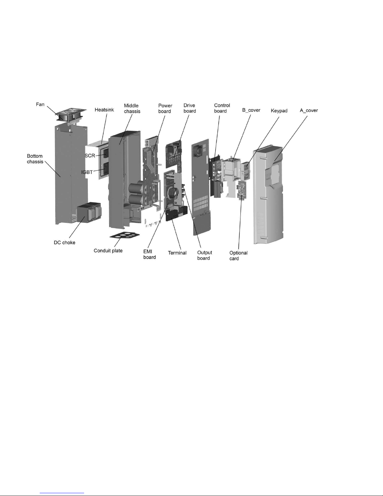
Component Identification
Figure 6. Description of the DG1 Series
Features
The DG1 frequency inverter converts the voltage and
frequency of an existing AC network into a DC voltage. This
DC voltage is used to generate a three-phase AC voltage
with adjustable frequency and assigned amplitude values for
the variable speed control of three-phase asynchronous
motors.
12 DG1 Series VFD MN040002EN—March 2014 www.eaton.com
 Loading...