

Eaton DeviceNet Product Operated Network Interface Instruction Leaflet
Instruction Leaflet IL17559 Rev. D Effective August 2009
Instructions for the DeviceNet® Product
Operated Network Interface (DPONI)
Contents
Description Page
The DPONI................................................................................. 3
DPONI DeviceNet Basics ......................................................... 3
Installation.................................................................................. 3
Networking ................................................................................ 4
Master Device................................................................. 4
Slave Device.................................................................... 4
Simplified Wiring Rules ............................................................. 4
Operational Check..................................................................... 4
LED Definitions and Diagnostics ..............................................4
Combined Module/Network Status (NS) LED ................ 4
5 WIRE TX .................................................................... 5
Troubleshooting......................................................................... 5
Specifications............................................................................. 5
DeviceNet Cable Specifications ...................................... 5
Maintenance and Care .............................................................. 5
Appendix A: Parameter Object Instances for MP-3000 .......... 6
Appendix B: Assembly Object Instances for MP-3000 ........... 9
Appendix C: Parameter Object Instances for MP-4000 ........ 14
Appendix D: Assembly Object Instances for MP-4000.........18
Contact Information.................................................................24

Copyright © 2009 by Eaton Corporation. All rights reserved.
Specifications and information contained herein are subject to change without notice.
EATON CORPORATION - CONFIDENTIAL AND PROPRIETARY NOTICE TO PERSONS RECEIVING THIS DOCUMENT
AND/OR TECHNICAL INFORMATION:
THIS DOCUMENT, INCLUDING THE DRAWING AND INFORMATION CONTAINED THEREON, IS CONFIDENTIAL AND IS
THE EXCLUSIVE PROPERTY OF EATON CORPORATION, AND IS MERELY ON LOAN AND SUBJECT TO RECALL BY EATON
AT ANY TIME. BY TAKING POSSESSION OF THIS DOCUMENT, THE RECIPIENT ACKNOWLEDGES AND AGREES THAT
THIS DOCUMENT CANNOT BE USED IN ANY MANNER ADVERSE TO THE INTERESTS OF EATON, AND THAT NO
PORTION OF THIS DOCUMENT MAY BE COPIED OR OTHERWISE REPRODUCED WITHOUT THE PRIOR WRITTEN
CONSENT OF EATON. IN THE CASE OF CONFLICTING CONTRACTUAL PROVISIONS, THIS NOTICE SHALL GOVERN THE
STATUS OF THIS DOCUMENT.
DISCLAIMER OF WARRANTIES AND LIMITATION OF LIABILITY:
The information, recommendations, descriptions, and safety notations in this document are based on Eaton Electrical Inc. and/or
Eaton Corporation’s (“Eaton”) experience and judgment and may not cover all contingencies. If further information is required, an
Eaton sales office should be consulted.
Sale of the product shown in this literature is subject to the terms and conditions outlined in appropriate Eaton selling policies or
other contractual agreement between Eaton and the purchaser.
THERE ARE NO UNDERSTANDINGS, AGREEMENTS, WARRANTIES, EXPRESSED OR IMPLIED, INCLUDING WARRANTIES
OF FITNESS FOR A PARTICULAR PURPOSE OR MERCHANTABILITY, OTHER THAN THOSE SPECIFICALLY SET OUT IN
ANY EXISTING CONTRACT BETWEEN THE PARTIES. ANY SUCH CONTRACT STATES THE ENTIRE OBLIGATION OF
EATON. THE CONTENTS OF THIS DOCUMENT SHALL NOT BECOME PART OF OR MODIFY ANY CONTRACT BETWEEN
THE PARTIES.
In no event will Eaton be responsible to the purchaser or user in contract, in tort (including negligence), strict liability, or
otherwise for any special, indirect, incidental, or consequential damage or loss whatsoever, including but not limited to
damage or loss of use of equipment, plant or power system, cost of capital, loss of power, additional expenses in the use
of existing power facilities, or claims against the purchaser or user by its customers resulting from the use of the
information, recommendations and descriptions contained herein.
Instructions for the DeviceNet® Product Instruction Leaflet IL17559 Rev. D
Operated Network Interface (DPONI) Effective August 2009
CAUTION
DE-ENERGIZE THE DEVICE TO WHICH THE DPONI WILL BE
ATTACHED OR WIRED. OTHERWISE, IMPROPER OPERATION OF OR
DAMAGE TO THE EQUIPMENT MAY OCCUR.
The DPONI
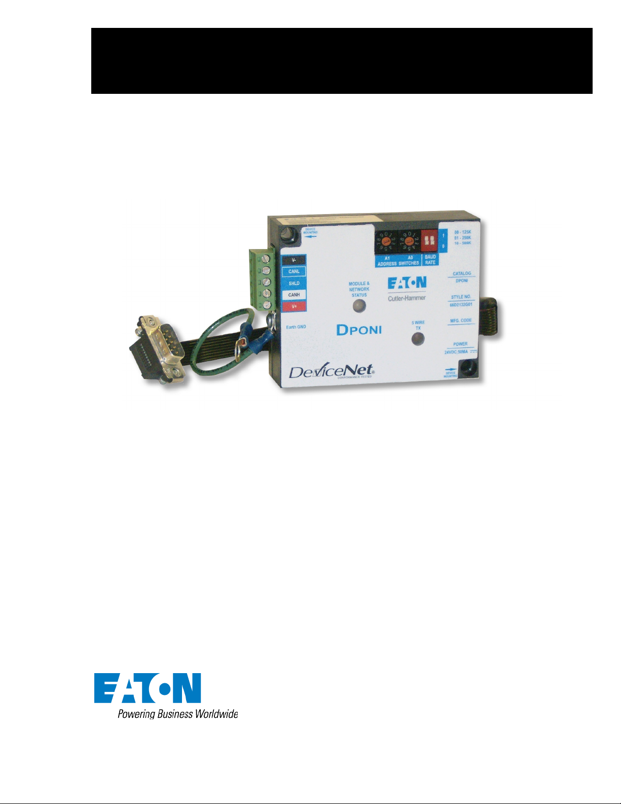
The DeviceNet® Product Operated Network Interface (DPONI)
enables communications between a DeviceNet network master
station and a host device in a master/slave format over a
DeviceNet network. The DPONI is compatible with the MP3000 and MP-4000. The DPONI is powered by the host product
to which it is attached as well as by the DeviceNet network. The
DPONI uses opto-couplers to isolate the two power systems.
The DPONI communicates at 125 Kbps or 250 Kbps, selected via
a front panel DIP switch. 500 Kbps is fully supported. All
products on the DeviceNet network must be set at the same
communications (baud) rate. A baud rate setting with both
switches set to the “up” or “1” position is illegal. If they are set
this way at startup, the DPONI will not operate.
The DPONI has a bicolor network/module status LED that
functions in accordance with the DeviceNet specification. An
additional monocolor LED flashes while the DPONI is receiving a
message from the host device.
Figure 1. The Eaton Cutler-Hammer DPONI.
DPONI DeviceNet Basics
The maximum number of DeviceNet nodes is limited to 64.
Therefore, the DeviceNet protocol limits addresses to a range of
0 to 63, with address 0 reserved for the DeviceNet master.
Setting the address switches to any value greater than 63 is
Illegal. If the address switches are set to values higher than 63 at
startup, the status LED will be solid red and the DPONI will not
operate. The DPONI supports explicit mode and polled I/O
connections. Volume 3 of the CIP Networks Library provides details
of these communications modes.
The DPONI must be reset following an address change via the
address switches by removing power from the DPONI host
connection. This can be accomplished by cycling power to the
host device.
The DPONI allows monitoring and control only. Changing
setpoints is not supported. The DPONI is a Group 2 DeviceNet
product. Group 4 functionality is not supported.
Installation
The DPONI is designed to be installed, operated, and maintained
by adequately trained personnel. These instructions do not cover
all details, variations, or combinations of the equipment, its
storage, delivery, installation, check-out, safe operation, or
maintenance.
The installer must comply with the National Electric Code and
local codes or regulations, as well as safety practices, for this
class of equipment.
The following instructions apply to installation.
1. Ensure that mounting screws for the DPONI have been
included.
Item Qty.
#8-32 X 1-1/8” Screw 2
2. Check the instruction leaflet mounting instructions for a
DPONI compatible host device. The following steps cover
the common examples of mounting instructions. In all
cases, the DPONI is to be mounted in a horizontal manner.
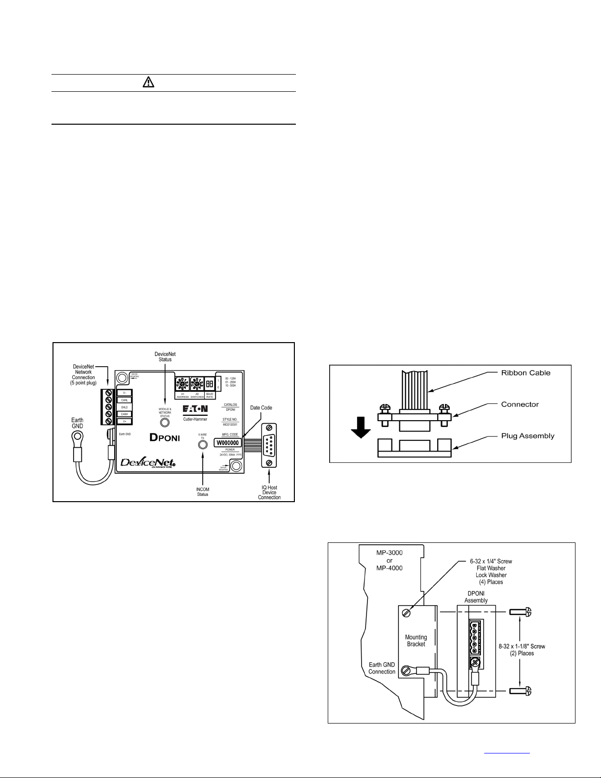
3. Disconnect power to the host device. Mount the DPONI to
the threaded head stacking screws of the power module
with the screws included with the DPONI. Mount the
DPONI with the LEDs on top and the ribbon cable on the
right. Connect the ribbon cable from the DPONI to the
receptacle of the host device (see Figure 2). Screw the plug
lock assembly tight.
Figure 2. Attaching the Ribbon Cable to the Host Device’s
Plug Lock Assembly.
4. Plug the DeviceNet into the device using the 5-point terminal
block. Repower the host device. The DPONI earth ground
(GND) wire must be mounted to the host device chassis, as
shown in Figure 3.
Figure 3. Mounting of DPONI Device.
EATON CORPORATION www.eaton.com
3
Instruction Leaflet IL17559 Rev. D Instructions for the DeviceNet
Effective August 2009 Operated Network Interface (DPONI)
®
Product
CAUTION
1. DO NOT INSTALL THE DPONI IN LOCATIONS WHERE THE
TEMPERATURE AT THE UNIT FALLS OUTSIDE THE RANGE OF –
20 C TO 70 C (-4 F TO 158 F). COOLING EQUIPMENT, SUCH AS
A FAN, SHOULD BE USED TO LOWER THE TEMPERATURE IF
THE 70 C (158 F) LIMIT IS EXCEEDED. HEATING EQUIPMENT
SHOULD BE PROVIDED IF THE –20 C (-4 F) LIMIT IS
EXCEEDED.
2. DO NOT INSTALL THE UNIT WHERE THE RELATIVE HUMIDITY
EXCEEDS 90% OR WHERE CONDENSATION FORMS DUE TO
RAPID TEMPERATURE CHANGES. A HEATER SHOULD BE
PROVIDED TO PREVENT THE FORMATION OF CONDENSATION.
3. DO NOT INSTALL THE UNIT WHERE DUST, SALT, OR IRON
PARTICLE DENSITIES ARE HIGH.
4. DO NOT INSTALL THE UNIT WHERE IT MAY BE SUBJECTED TO
DIRECT IMPACT OR VIBRATION.
Networking
Master Device
The control station for the DeviceNet network must be a unit,
such as a PC or PLC, which acts as a DeviceNet master.
EDS files for the MP-4000 (MP-4000.EDS) and MP-3000
(MP3000.EDS) are on the disc shipped with the DPONI. The
latest version of each of these files is also available on the Eaton
Corporation Website (www.eaton.com).
Slave Device
A DPONI must be used as a slave device with a DeviceNet
network to provide communications with the MP-3000 or MP-
4000.
Simplified Wiring Rules
For complete wiring rules, refer to the DeviceNet Specification.
The DeviceNet configuration must comply with the rules for
trunk and drop cable configuration and length. The following list
provides the basic wiring rules.
• Terminating resistors are required on each end of the trunk
line.
• The trunk must be configured as a linear bus.
• Drop lines may be as long as 6 m (20 ft) and may contain
branches. The cumulative drop length for thin or thick cable
is limited to 156 m (512 ft) for 125 Kbps, 78 m (256 ft) for
250 Kbps, and 39 m (128 ft) for 500Kbps.
• The maximum total cable distance at all baud rates is 100 m
(328 ft) for thin trunk cable.
• The maximum total cable distance at 125 Kbps is 500 m
(1640 ft) for thick trunk cable.
• The maximum total cable distance at 250 Kbps is 250 m
(820 ft) for thick trunk cable.
• The maximum total cable distance at 500 Kbps is 100 m
(328 ft) for thick trunk cable.
• The maximum length of mixed cables may be found by
solving the following equation:
L
+ 5*L
Thick
L
must not exceed 156 m (511 ft).
Thin
= 500 m (1640 ft).
Thin
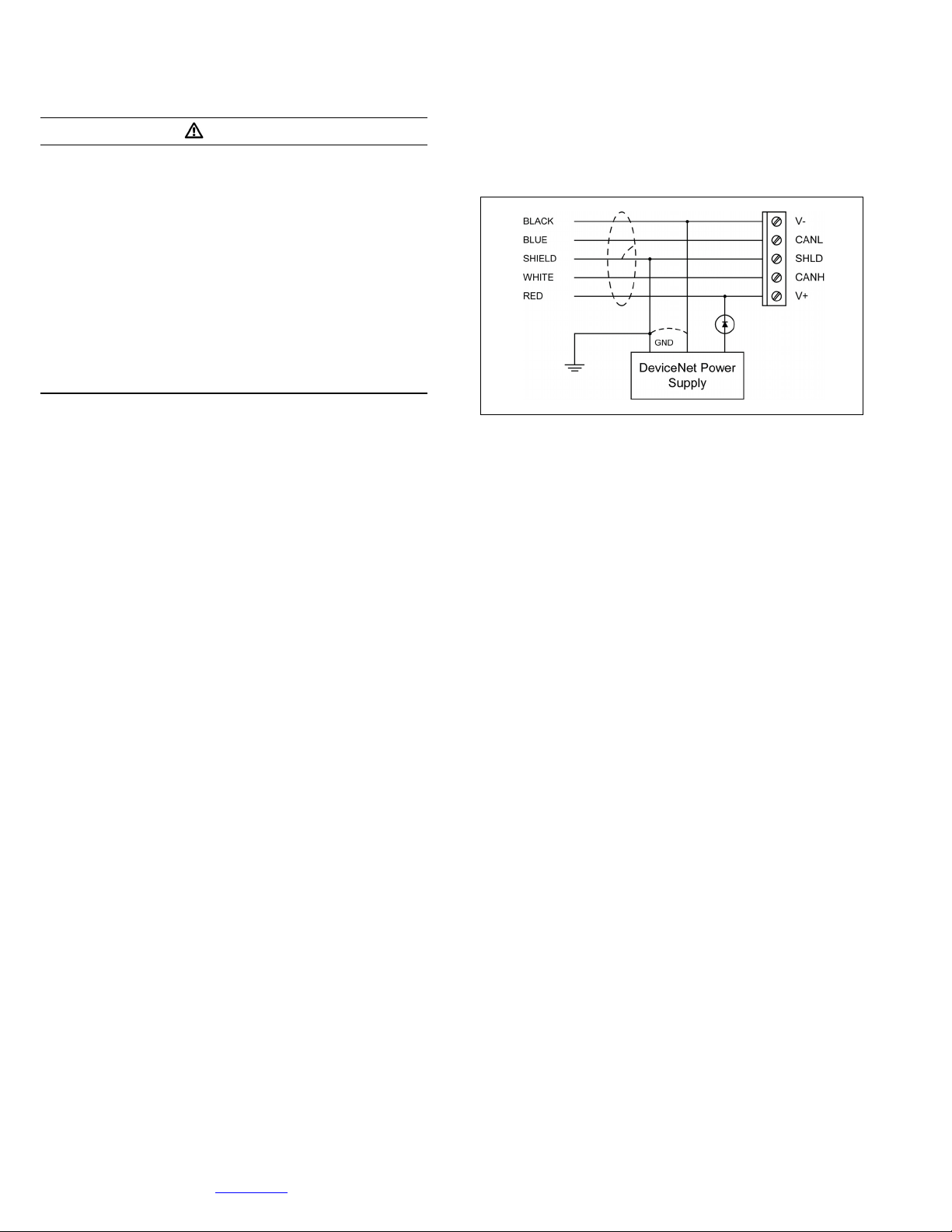
The most common power configuration is shown in Figure 4.
The 5-point plug connector should be wired with cable approved
for DeviceNet applications. The colors of the wires should be
matched to the DPONI label.
Figure 4. Typical DeviceNet Power Configuration.
The DeviceNet cable insulation should be stripped back
approximately 1 in. (25.4 mm) from the end. Each of the wires
should be stripped approximately ¼ in. (6.5 mm). The terminals
of the DeviceNet connector should be tightened to 5 to 7 in-lbs
(0.57 to 0.79 N-m). The drop cable can be daisy chained by
terminating two wires under one screw.
Operational Check
After the DeviceNet system has been installed, check the
operation of the DPONI by applying power to the host device and
to the DeviceNet network. When under power from both
sources, the bicolor LED should:
• Turn green for approximately 0.25 second;
• Turn red for approximately 0.25 second; then
• Turn off.
Note that a minimum of two nodes (a master and a slave) must
be under power for the Duplicate MAC ID check to complete
successfully.
The DPONI does not support network-settable addressing. The
DPONI address is entirely switch- dependent. Each DPONI is
shipped with its address switches set to 63.
The DPONI’s bicolor combined network/status LED functions as
defined in the DeviceNet Specification. In brief, after DPONI
initialization, the status LEDs perform as described in the
following section of this instruction leaflet.
LED Definitions and Diagnostics
During the power-up initialization sequence, all three bicolor LEDs
should blink green, then red, then off. This indicates that all three
LEDs are functioning correctly. After initialization, these LEDs
function according to the following descriptions.
Combined Module/Network Status (NS) LED
The Combined Module/Network Status (NS) LED provides an
indication of the status of the DeviceNet Network as listed in
Table 1.
4
EATON CORPORATION www.eaton.com

Instructions for the DeviceNet® Product Instruction Leaflet IL17559 Rev. D
Operated Network Interface (DPONI) Effective August 2009
Table 1. Combined Module/Network Status (NS) LED
For This State: LED Is: To Indicate:
DPONI Not Powered/
Not Online
DPONI Operational AND
Online, Connected
Off The DPONI is not online.
Green The DPONI is operating in a
normal condition and is online
with connections in the
established state.
5 WIRE TX
The 5 WIRE TX is a monocolor LED that flashes whenever the
DPONI is receiving communications from the attached host
device.
Troubleshooting
In the unlikely event the LEDs do not function as previously
described, the following items should be checked.
1. If all LEDs remain off, check to make sure that the
DeviceNet terminal plug is connected and that the
DeviceNet network is under power.
2. If the combined Module/Network status LED blinks red
and/or green, check to make sure that all the DeviceNet
devices on the network are communicating at the same rate
(125, 250, or 500 Kbps).
3. If the combined Module/Network status LED blinks green,
then red, and then turns solid red, check to make sure that
there is a master node on the DeviceNet network and that
appropriate application software has been installed and is
functioning correctly on that master node. Then, check to
ensure that this DPONI node has a unique MAC ID.
4. If the 5-WIRE LED remains off, check the function of the
host device on which the DPONI is mounted. If it is
connected, powered, and showing correct readings on the
faceplate, remove the DPONI’s ribbon cable from the unit
and reattach it.
5. Check the DeviceNet network wiring for loose connections,
shorted wires, etc.
6. If suggestions 1 through 5 do not remedy the problem, the
DPONI may need to be replaced.
CAUTION
DO NOT ATTEMPT TO SERVICE THIS EQUIPMENT. OTHERWISE,
SERIOUS INJURY OR DEATH AND/OR EQUIPMENT DAMAGE MAY
RESULT.
Specifications
Table 2. DeviceNet Connector Ratings.
Connector Rating
V+ 11 Vdc to 27 Vdc; inrush = 300 mA; steady state = 40 mA;
V- DeviceNet common
CANH Reverse wiring protected to +/- 27 Vdc
CANL Reverse wiring protected to +/- 27 Vdc
DRAIN Shield tie point
maximum 3 VA
Table 3. System Ratings.
Item Rating
Operating Temperature
Storage Temperature
Altitude 3,048 m (10,000 ft)
Operating Humidity 5% to 90% maximum noncondensing
Environment Indoor use only
Transient Overvoltage Category 1
Pollution Degree 2
Communications Rate 125, 250, or 500 Kbps
-20 C to 70 C (-4 F to 158 F)
-20 C to 75 C (-4 F to 167 F)
DeviceNet Cable Specifications
For complete specifications, refer to the DeviceNet Specification.
“Thick” cable refers to DeviceNet trunk cable. “Thin” cable
refers to DeviceNet drop cable. “Both” refers to both trunk and
drop cable.
Table 4. Cable Characteristics and Specifications.
Cable
Type
Both Impedance 120 ohms
Both Propagation Delay 1.36 nsec/ft maximum
Both Capacitance between conductors 12 pf/ft
Both Capacitance between a conductor and
Thick Capacitive Unbalance 370 pf/1,000 ft (304.8 m)
Thin Capacitive Unbalance 620 pf/1,000 ft (304.8 m)
Thick Attenuation at 125KHz 0.13 db/100 ft (30.5 m)
Thin Attenuation at 125KHz 0.29 db/100 ft (30.5 m)
Electrical Characteristics Specification at 1MHz
24 pf/ft
the shield
Maintenance and Care
The DPONI is designed to be a self-contained and maintenancefree unit. The printed circuit board is calibrated and conformally
coated at the factory. The DPONI is intended to be serviced by
factory-trained personnel only. NEVER clean the DPONI with
host or DeviceNet power on. Clean the DPONI using only a
clean, dry cloth. Do not use water or solvents of any kind.
EATON CORPORATION www.eaton.com
5

Instruction Leaflet IL17559 Rev. D Instructions for the DeviceNet
®
Product
Effective August 2009 Operated Network Interface (DPONI)
Appendix A: Parameter Object Instances for MP-3000
Table A-1. Parameter Object Instances for MP-3000.
Inst # Name Units Type Byte Access Min Max Scaling
Divisor
1 Reserved - - - - - - - 2 Reserved - - - - - - - 3 ConsumedIoAssy UINT 2 Set/Get 100 104 1 0 4 ConsumedIoSize UINT 2 Get 2 2 1 0 5 ProducedIoAssy UINT 2 Set/Get 150 164 1 0 6 ProducedIoSize UINT 2 Get 4 54 1 0 7 Reserved - - - - - - - 8 Reserved - - - - - - - -
9 Reserved - - - - - - - 10 Reserved - - - - - - - 11 Reserved - - - - - - - 12 Reserved - - - - - - - 13 Reserved - - - - - - - 14 Reserved - - - - - - - 15 Reserved - - - - - - - 16 Reserved - - - - - - - 17 Reserved - - - - - - - 18 Reserved - - - - - - - 19 Reserved - - - - - - - 20 Reserved - - - - - - - 21 Reserved - - - - - - - 22 Reserved - - - - - - - 23 Reserved - - - - - - - 24 Reserved - - - - - - - 25 Reserved - - - - - - - 26 Reserved - - - - - - - 27 Reserved - - - - - - - 28 Reserved - - - - - - - 29 Reserved - - - - - - - 30 Reserved - - - - - - - 31 Reserved - - - - - - - 32 Status UINT 2 Get 0 7 1 0 (300)
33 StatusByte WORD 2 Get 0 255 1 0 (300)
34 ProductId UINT 2 Get 0 63 1 0 (300)
35 DivisionCode UINT 2 Get 0 63 1 0 (300)
36 CommVersion UINT 2 Get 0 15 1 0 (300)
37 FlagsStatus UINT 2 Get 0 6 1 0 (3C8)
38 FlagsReason UINT 2 Get 0 40 1 0 (3C8)
39 SlaveActions WORD 2 Set/Get 0 65535 1 0 (3D0)
40 WindingTemp1 DegC INT 2 Get -1 255 1 0 (30F, N=1)
41 WindingTemp2 DegC INT 2 Get -1 255 1 0 (30F, N=1)
42 WindingTemp3 DegC INT 2 Get -1 255 1 0 (30F, N=1)
43 WindingTemp4 DegC INT 2 Get -1 255 1 0 (30F, N=1)
44 WindingTemp5 DegC INT 2 Get -1 255 1 0 (30F, N=1)
45 WindingTemp6 DegC INT 2 Get -1 255 1 0 (30F, N=1)
46 MotorBrngTemp1 DegC INT 2 Get -1 255 1 0 (30F, N=1)
47 MotorBrngTemp2 DegC INT 2 Get -1 255 1 0 (30F, N=1)
48 LoadBrngTemp1 DegC INT 2 Get -1 255 1 0 (30F, N=1)
49 LoadBrngTemp2 DegC INT 2 Get -1 255 1 0 (30F, N=1)
50 AuxiliaryTemp DegC INT 2 Get -1 255 1 0 (30F, N=1)
51 CurrentPhA A UINT 2 Get 0 65535 1 0 (30F, N=3)
52 CurrentPhB A UINT 2 Get 0 65535 1 0 (30F, N=3)
53 CurrentPhC A UINT 2 Get 0 65535 1 0 (30F, N=3)
54 CurrentGnd A UINT 2 Get 0 65535 1 0 (30F, N=3)
55 CurrentAvg3Ph A UINT 2 Get 0 65535 1 0 (30F, N=3)
56 CurrentPhAPcntFl % UINT 2 Get 0 9999 100 1 (30F, N=28)
57 CurrentPhBPcntFl % UINT 2 Get 0 9999 100 1 (30F, N=28)
58 CurrentPhCPcntFl % UINT 2 Get 0 9999 100 1 (30F, N=28)
59 PcntPhaseUnbal % INT 2 Get -9999 9999 100 1 (30F, N=28)
60 PcntThermCapcty % UINT 2 Get 0 9999 100 1 (30F, N=28)
Scaling
Offset
Buffer
Accessed
6
EATON CORPORATION www.eaton.com

Instructions for the DeviceNet® Product Instruction Leaflet IL17559 Rev. D
Operated Network Interface (DPONI) Effective August 2009
Table A-1. Parameter Object Instances for MP-3000 (cont.).
Inst # Name Units Type Byte Access Min Max Scaling
Divisor
61 TimeToNextStart Min UINT 2 Get 0 255 1 1 (30F, N=28)
62 RemainStartsCnt UINT 2 Get 0 255 1 1 (30F, N=28)
63 TimeOldestStart Min UINT 2 Get 0 255 1 1 (30F, N=28)
64 MaxStartCurrent A UINT 2 Get 0 65535 1 0 (30F, N=25)
65 MaxRunCurrent A UINT 2 Get 0 65535 1 0 (30F, N=25)
66 MaxPhaseUnbal A UINT 2 Get 0 65535 1 0 (30F, N=25)
67 MaxWindingTemp DegC INT 2 Get -1 255 1 0 (30F, N=25)
68 MaxMotBrngTemp DegC INT 2 Get -1 255 1 0 (30F, N=25)
69 MaxLoadBrngTemp DegC INT 2 Get -1 255 1 0 (30F, N=25)
70 MxLastResetDateM Mnth UINT 2 Get 1 12 1 0 (30F, N=25)
71 MxLastResetDateD Day UINT 2 Get 1 31 1 0 (30F, N=25)
72 MxLastResetDateY Year UINT 2 Get 2001 2099 1 0 (30F, N=25)
73 MxLastResetTimeH Hour UINT 2 Get 0 23 1 0 (30F, N=25)
74 MxLastResetTimeM Min UINT 2 Get 0 59 1 0 (30F, N=25)
75 MxLastResetTimeS Sec UINT 2 Get 0 59 1 0 (30F, N=25)
76 MotorStartsCnt UINT 2 Get 0 65535 1 0 (30F, N=25)
77 MotorRunTime Hour UINT 2 Get 0 65535 1 0 (30F, N=25)
78 MotorEmrgOvrdCnt UINT 2 Get 0 65535 1 0 (30F, N=25)
79 MoLastResetDateM Mnth UINT 2 Get 1 12 1 0 (30F, N=25)
80 MoLastResetDateD Day UINT 2 Get 1 31 1 0 (30F, N=25)
81 MoLastResetDateY Year UINT 2 Get 2001 2099 1 0 (30F, N=25)
82 MoLastResetTimeH Hour UINT 2 Get 0 23 1 0 (30F, N=25)
83 MoLastResetTimeM Min UINT 2 Get 0 59 1 0 (30F, N=25)
84 MoLastResetTimeS Sec UINT 2 Get 0 59 1 0 (30F, N=25)
85 TotalStartsCnt UINT 2 Get 0 65535 1 0 (30F, N=25)
86 TotalRunTime Hour UINT 2 Get 0 65535 1 0 (30F, N=25)
87 TotalTripsCnt UINT 2 Get 0 65535 1 0 (30F, N=25)
88 GndFaultTripsCnt UINT 2 Get 0 255 1 0 (30F, N=26)
89 I2TtripsCnt UINT 2 Get 0 255 1 0 (30F, N=26)
90 InstOCurTripsCnt UINT 2 Get 0 255 1 0 (30F, N=26)
91 JamTripsCnt UINT 2 Get 0 255 1 0 (30F, N=26)
92 UndrLdTripsCnt UINT 2 Get 0 255 1 0 (30F, N=26)
93 PhsUnbalTripsCnt UINT 2 Get 0 255 1 0 (30F, N=26)
94 WindTempTripsCnt UINT 2 Get 0 255 1 0 (30F, N=26)
95 MotrBrngTripsCnt UINT 2 Get 0 255 1 0 (30F, N=26)
96 LoadBrngTripsCnt UINT 2 Get 0 255 1 0 (30F, N=26)
97 AuxTempTripsCnt UINT 2 Get 0 255 1 0 (30F, N=26)
98 PhsRvrsTripsCnt UINT 2 Get 0 255 1 0 (30F, N=26)
99 IncmSeqTripsCnt UINT 2 Get 0 255 1 0 (30F, N=26)
100 RemoteTripsCnt UINT 2 Get 0 255 1 0 (30F, N=26)
101 DiffrntlTripsCnt UINT 2 Get 0 255 1 0 (30F, N=26)
102 StrtPerTTripsCnt UINT 2 Get 0 255 1 0 (30F, N=26)
103 TBtnStrtTripsCnt UINT 2 Get 0 255 1 0 (30F, N=26)
104 XsitionTripsCnt UINT 2 Get 0 255 1 0 (30F, N=26)
105 TripBypsTripsCnt UINT 2 Get 0 255 1 0 (30F, N=26)
106 ZeroSpdSTripsCnt UINT 2 Get 0 255 1 0 (30F, N=26)
107 TcLastResetDateM Mnth UINT 2 Get 1 12 1 0 (30F, N=26)
108 TcLastResetDateD Day UINT 2 Get 1 31 1 0 (30F, N=26)
109 TcLastResetDateY Year UINT 2 Get 2001 2099 1 0 (30F, N=26)
110 TcLastResetTimeH Hour UINT 2 Get 0 23 1 0 (30F, N=26)
111 TcLastResetTimeM Min UINT 2 Get 0 59 1 0 (30F, N=26)
112 TcLastResetTimeS Sec UINT 2 Get 0 59 1 0 (30F, N=26)
113 GndFaultAlrmsCnt UINT 2 Get 0 255 1 0 (30F, N=27)
114 I2TAlrmsCnt UINT 2 Get 0 255 1 0 (30F, N=27)
115 JamAlrmsCnt UINT 2 Get 0 255 1 0 (30F, N=27)
116 UndrLdAlrmsCnt UINT 2 Get 0 255 1 0 (30F, N=27)
117 PhsUnbalAlrmsCnt UINT 2 Get 0 255 1 0 (30F, N=27)
118 WindTempAlrmsCnt UINT 2 Get 0 255 1 0 (30F, N=27)
119 MotrBrngAlrmsCnt UINT 2 Get 0 255 1 0 (30F, N=27)
120 LoadBrngAlrmsCnt UINT 2 Get 0 255 1 0 (30F, N=27)
Scaling
Offset
Buffer
Accessed
EATON CORPORATION www.eaton.com
7

Instruction Leaflet IL17559 Rev. D Instructions for the DeviceNet
®
Product
Effective August 2009 Operated Network Interface (DPONI)
Table A-1. Parameter Object Instances for MP-3000 (cont.).
Inst # Name Units Type Byte Access Min Max Scaling
Divisor
121 AuxTempAlrmsCnt UINT 2 Get 0 255 1 0 (30F, N=27)
122 StrtPerTAlrmsCnt UINT 2 Get 0 255 1 0 (30F, N=27)
123 RtdFailAlrmsCnt UINT 2 Get 0 255 1 0 (30F, N=27)
124 URtdFailAlrmsCnt UINT 2 Get 0 255 1 0 (30F, N=27)
125 AcLastResetDateM Mnth UINT 2 Get 1 12 1 0 (30F, N=27)
126 AcLastResetDateD Day UINT 2 Get 1 31 1 0 (30F, N=27)
127 AcLastResetDateY Year UINT 2 Get 2001 2099 1 0 (30F, N=27)
128 AcLastResetTimeH Hour UINT 2 Get 0 23 1 0 (30F, N=27)
129 AcLastResetTimeM Min UINT 2 Get 0 59 1 0 (30F, N=27)
130 AcLastResetTimeS Sec UINT 2 Get 0 59 1 0 (30F, N=27)
131 FlagsBitsB15B00 WORD 2 Get 0 65535 1 0 (3C8)
132 FlagsBitsB31B16 WORD 2 Get 0 65535 1 0 (3C8)
133 FlagsBitsB47B32 WORD 2 Get 0 65535 1 0 (3C8)
134 FlagsBitsB63B48 WORD 2 Get 0 65535 1 0 (3C8)
135 DiscreteInputs WORD 2 Get 0 3 1 0 (3C8)
136
137
138
139
140
141
142
143
144
145
146
147
148
149
150
151
152
153
154
155
156
157
158
159
160
161
162
163
164
165
166
167
168
169
170
171
172
173
174
175
176
177
178
179
180
Scaling
Offset
Buffer
Accessed
8
EATON CORPORATION www.eaton.com
 Loading...