

Eaton DeviceNet E50DNA, DeviceNet E50DNAC Installation Instructions Manual
Installation Instructions for
DeviceNet™ E50 Limit Switches
MODELS COVERED BY THIS MANUAL
Catalog Number Description
E50DNA Solid State Switch Body
with 2-meter cable
E50DNAC Solid State Switch Body
with 5-pin DeviceNet
micro-connector
111032 Rev --Cutler-Hammer
DESCRIPTION
General Information
• Network Media - DeviceNet
• Protocol - DeviceNet Rel 2.0
• Type - Group 2 Only Slave Device using Predefined
Master Slave Connection Set
• Bandwidth - 125, 250, 500 Kbaud
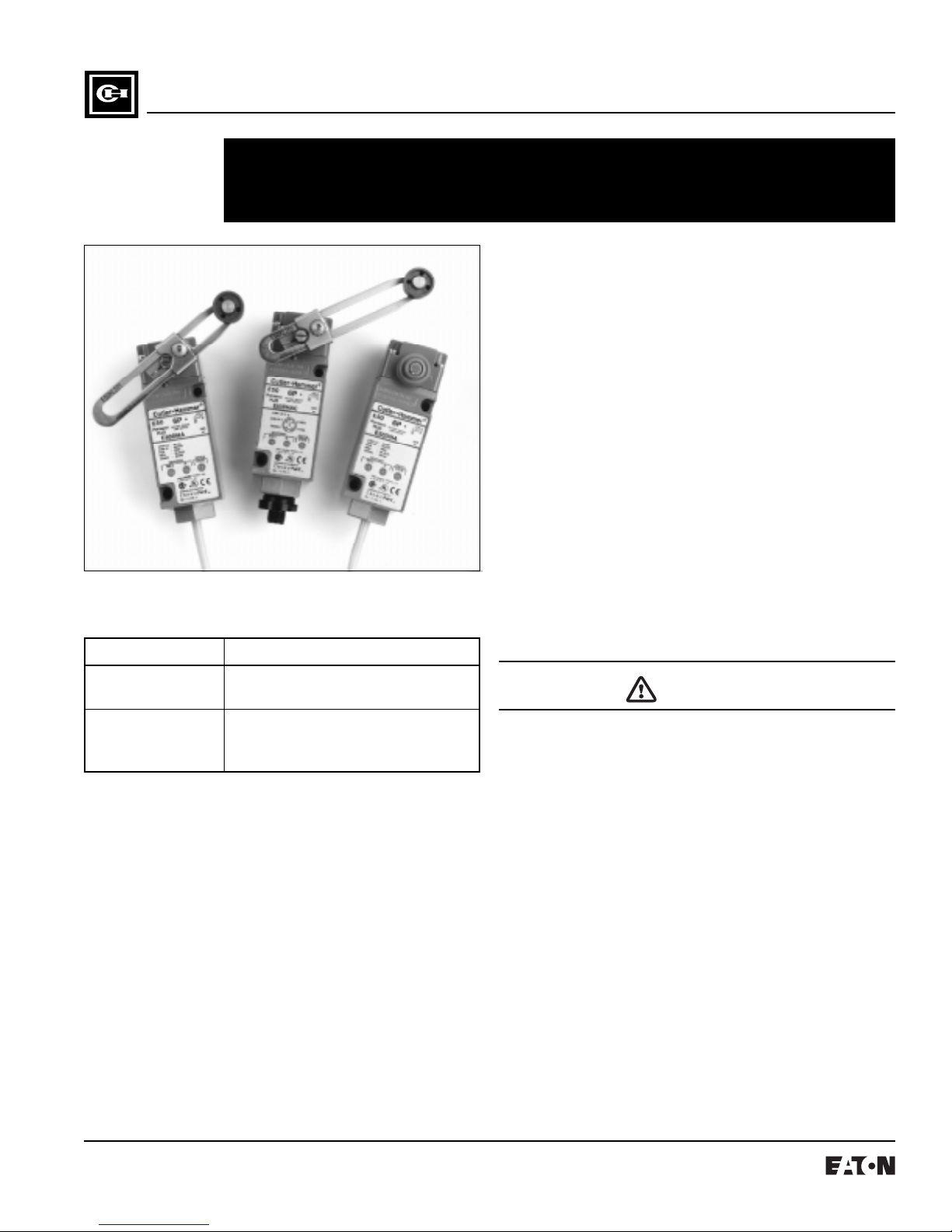
All E50 Limit Switches consist of two modular, interchangeable plug-in components: operating head and a solid state
switch body. Operating heads (side rotary, top and side
push, and wobble stick) are mounted on top of the switch
body in any of four positions. All assembled limit switches are
rated NEMA 3, 3S, 4, 4X, 6, 6P and 13. Obtain renewal parts by
ordering the catalog number labeled on each of the two limit
switch components.
NEMA ICS 2-225 describes preferred installation recommendations which ensure greatest reliability and longest life expectancy for Industrial Limit Switches.
INSTALLATION
WARNING
DO NOT INSTALL OR PERFORM MAINTENANCE ON THIS
DEVICE WHILE THE CONTROLLER IS ENERGIZED. DEATH OR
SEVERE PERSONAL INJURY CAN RESULT FROM CONTACT
WITH ENERGIZED EQUIPMENT. VERIFY THAT NO VOLTAGE IS
PRESENT BEFORE PROCEEDING WITH INSTALLATION OR
MAINTENANCE. Only qualified persons, as defined in the
National Electric Code, who are familiar with the installation,
maintenance and operation of this device and the equipment
onto which is to be installed, as well as applicable local, state
and national regulations and industry standards and
accepted practices regarding safety of personnel and the
equipment safety should be permitted to install, maintain or
operate this device. These instructions are provided only as
a general guide to such qualified persons and are not allinclusive. They do not cover every application or circumstances which may arise in the installation, maintenance or
operation of this equipment. Users are advised to comply
with all local, state and national regulations and industry
standards and accepted practices regarding safety of
personnel and the equipment safety.
111032 Rev --Page 2
TORQUE REQUIREMENTS FOR LIMIT SWITCH ASSEMBLY
Tighten the operating head screws to a torque value within the
following ranges to ensure and maintain the Enclosure Type
Ratings for the assembled limit switch.
Operating Head Screws — Tighten to ensure contact of head
to switch body: 14 - 18 lb. in.
OPERATING HEAD POSITIONING
Heads can be mounted on the switch body in any of four
directions, 90° apart. Torque screws according to requirements on page 1.
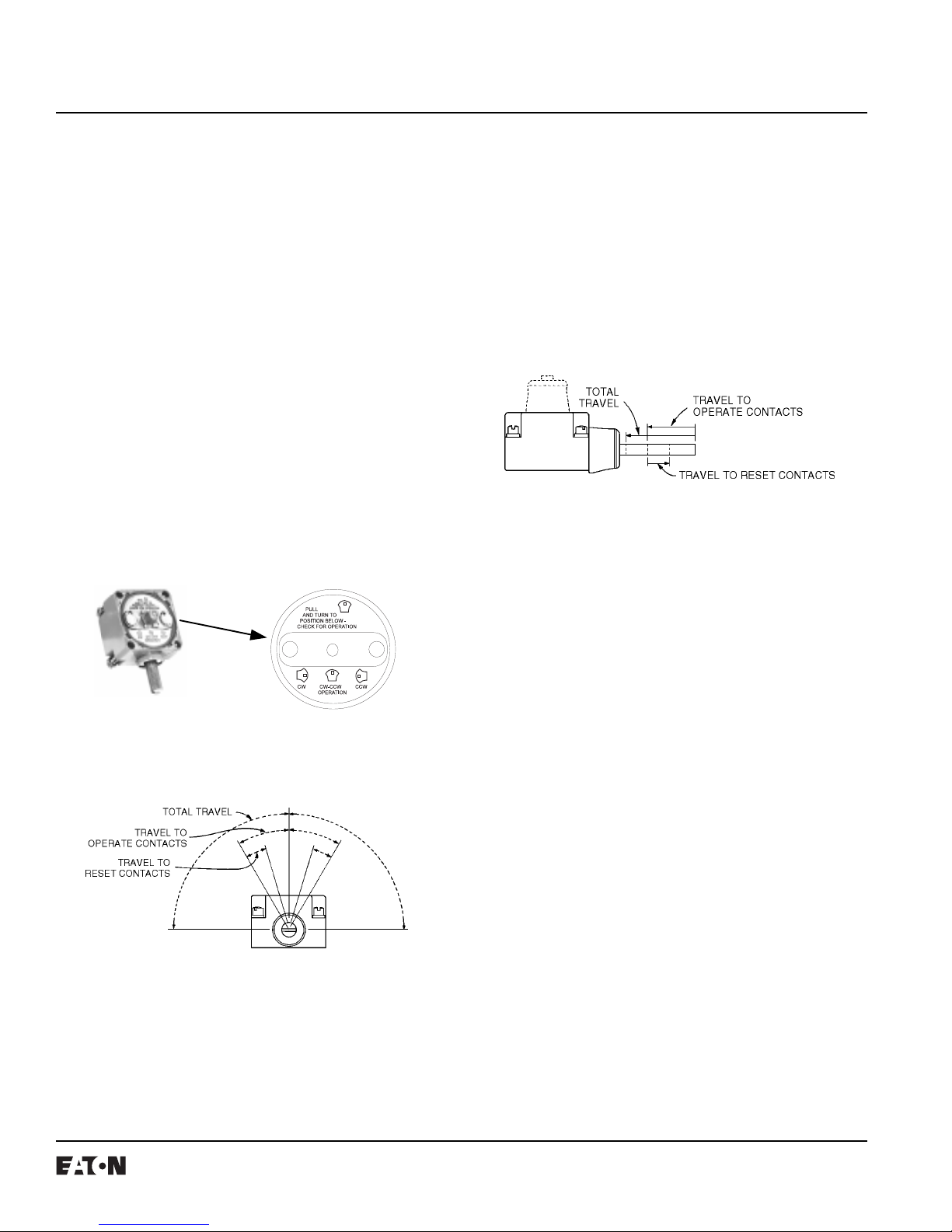
OPERATING HEADS — SIDE ROTARY
The operating mode (CW, CCW or CW and CCW) of these
spring return operating heads is easily changed without
tools as shown in the illustration. Remove the head from
switch body. Pull out the plunger and turn until its position
matches that shown on the diagram for the desired operation mode. Levers are adjustable to any angle (360°). The
operating shaft screwdriver slot can be used to maintain
shaft position during lever installation.
OPERATING HEADS — PUSH OPERATED
These spring return top push or side push operating heads
are available in pushbutton and roller styles.
The push roller style can be converted from vertical to
horizontal operation or vice versa. Pull roller out of the head
until it can be rotated 90° to the desired orientation. When
released, it will snap into the set position.
The Maintained Contact head has the reset pushbutton
located opposite of the actuator pushbutton.
Push Operational Head
OPERATING HEADS — WOBBLE STICK
These spring return, top operated heads use different rodtype operators to detect motion in any direction perpendicular to the operator. The operator screws onto the threaded
head stub.
Set Operating Head Mode
Before Assembly
Side Rotary Operational Head
Bottom View of Side Operated
Rotary Head (Note Mode Change
Instructions in Head)
Effective 9/97
111032 Rev -- Page 3
REPEAT ACCURACY
The type of operating head used on an assembled limit
switch determines repeat accuracy for the switch assembly.
Assembled limit switches, without rollers used on operating
heads or levers, have a repeat accuracy as listed in Table 1
only.
Assembled limit switches with rollers used on operating
heads or levers have a repeat accuracy determined as
follows: add the repeat accuracy tolerance of Table 1 for the
type of operating head used to the concentricity tolerance of
Table 2 for the type of roller used on the lever or operator.
The combination of these two tolerances is the limit switch
repeat accuracy.
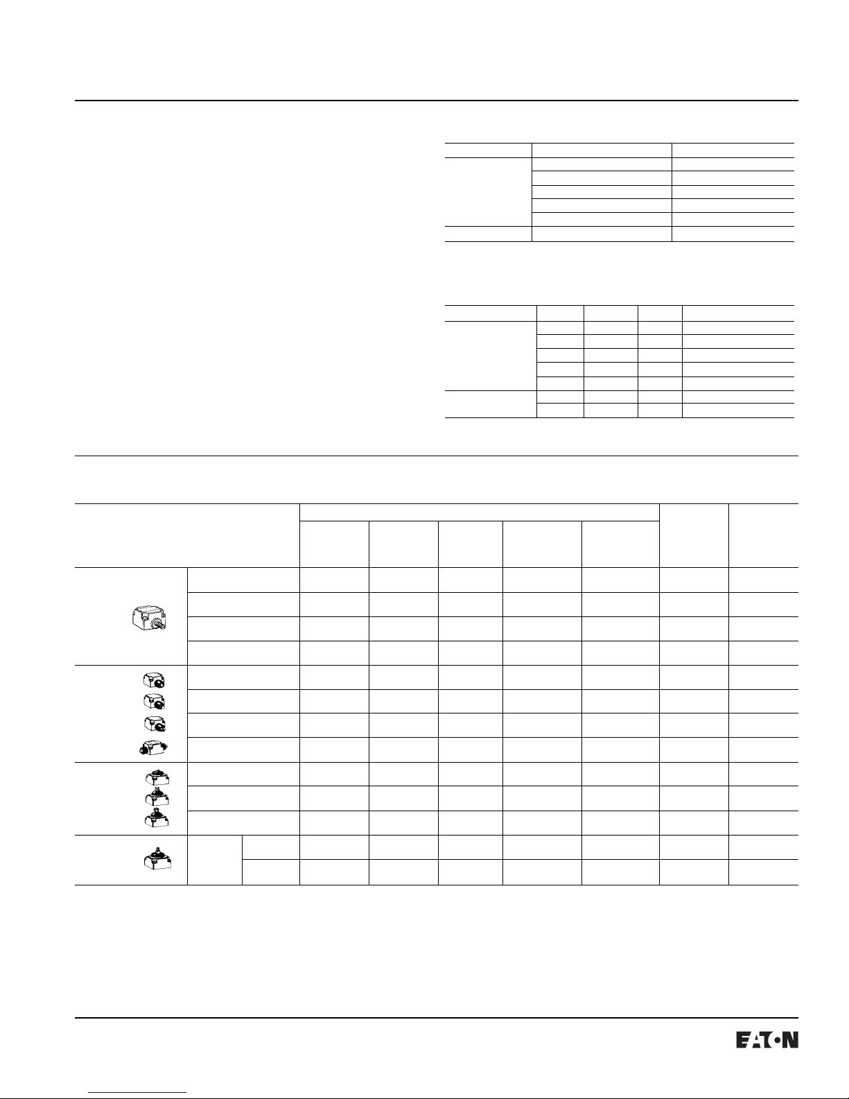
OPERATING HEAD DATA
Operating Data —Nominal Operating
Travel To Travel To Force To Minimum Temp.
Operate Reset
Contacts Contacts
5° 2 ° 90 ° 3 in.-lbs. 4.5 in.-oz. A E50DR1
5° 2 ° 90 ° 3 in.-lbs. 4.5 in.-oz. D E50DR19
15 ° 6° 90 ° 1.5 in.-lbs. 2.5 in.-oz. A E50DL1
50 ° 50 ° 90 ° 3 in.-lbs. — B E50DM1
0.065 in. 0.030 in. 0.290 in. 4 lbs. 8 oz. B E50DS1
0.065 in. 0.030 in. 0.290 in. 4 lbs. 8 oz. B E50DS2
0.065 in. 0.030 in. 0.290 in. 4 lbs. 8 oz. B E50DS3
0.200 in. 0.130 in. 0.320 in. 5 lbs. 5 lbs. B E50DH1
0.040 in. 0.020 in. 0.280 in. 4 lbs. 8 oz. C E50DT1
0.040 in. 0.020 in. 0.280 in. 4 lbs. 8 oz. C E50DT2
0.040 in. 0.020 in. 0.280 in. 4 lbs. 8 oz. C E50DT3
10 ° 6° 15 ° 2 in.-lbs. 2.4 in.-oz. C E50DW1
10 ° 6° 15 ° 2 in.-lbs. 2.4 in.-oz. C E50DW2
Side Rotary
Side Push
Top Push
Wobble Head
Description
Operating Heads
Standard
Spring Return
Low Temperature
Spring Return
Low Force
Spring Return
Maintained
Two position
Pushbutton
Spring Return
Pushbutton Adjustable
Spring Return
Push Roller
Spring Return
Pushbutton
Maintained
Pushbutton
Spring Return
Pushbutton Adjustable
Spring Return
Push Roller
Spring Return
Standard
Spring Duty
Return Heavy
Duty
TABLE 1
Side Operated Standard Construction within 0.0012”
Top Operated Top Push within 0.002”
1
Measured along arc for 1-1/2” lever or measured along push operator axis.
TABLE 2
Lever Roller Type Nylon 3/4” 5/16” +/-0.002”
Push Roller Type Metal 7/16” 5/32” +/-0.002”
Total
Travel
Contacts Force (See Table)
Operating Head Repeat Accuracy
Low Operating Force within 0.0024”
Two-Step within 0.006”
Neutral Position within 0.006”
Side Push within 0.003”
Type Diameter Width Concentricity Tolerance
Metal 3/4” 5/16” +/-0.001”
Nylon 3/4” 1” +/-0.005”
Ball Brg. 11/16” 1/4” +/-0.002”
Nylon 1-1/2” 9/32 +/-0.005”
Metal 3/4” 5/32” +/-0.005”
Operate Return Range
Catalog
No.
1
Effective 9/97
 Loading...