

Eaton DeviceNet User Manual
DeviceNet Option Board for 9000X Drive
User Manual
New Information
March 2004
MN04003005E
For more information visit: www.eatonelectrical.com

March 2004
Important Notice – Please Read
The product discussed in this literature is subject to terms and conditions outlined in Eaton
Electrical Inc. selling policies. The sole source governing the rights and remedies of any
purchaser of this equipment is the relevant Eaton Electrical Inc. selling policy.
NO WARRANTIES, EXPRESS OR IMPLIED, INCLUDING WARRANTIES OF FITNESS FOR A
PARTICULAR PURPOSE OR MERCHANTABILITY, OR WARRANTIES ARISING FROM COURSE
OF DEALING OR USAGE OF TRADE, ARE MADE REGARDING THE INFORMATION,
RECOMMENDATIONS AND DESCRIPTIONS CONTAINED HEREIN. In no event will Eaton
Electrical Inc. be responsible to the purchaser or user in contract, in tort (including
negligence), strict liability or otherwise for any special, indirect, incidental or consequential
damage or loss whatsoever, including but not limited to damage or loss of use of equipment,
plant or power system, cost of capital, loss of power, additional expenses in the use of
existing power facilities, or claims against the purchaser or user by its customers resulting
from the use of the information, recommendations and descriptions contained herein.
The information contained in this manual is subject to change without notice.
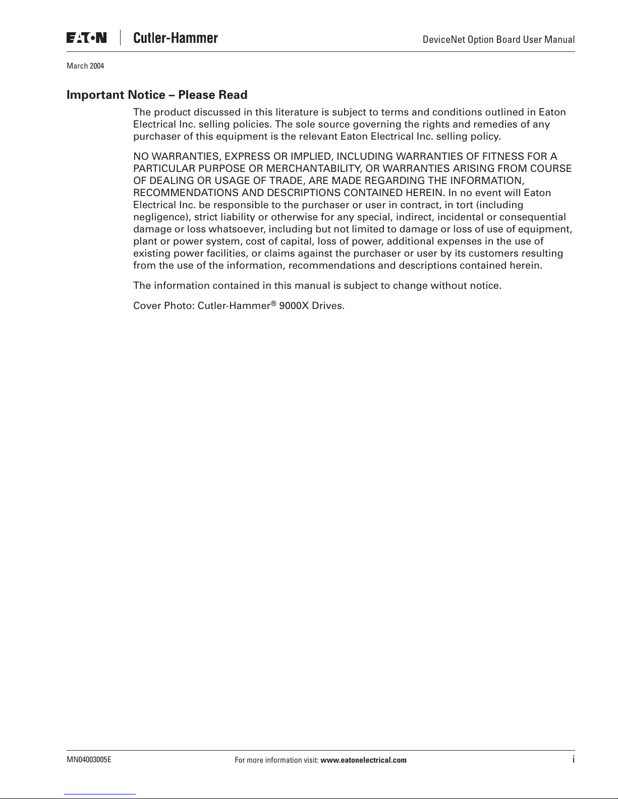
Cover Photo: Cutler-Hammer
®
9000X Drives.
DeviceNet Option Board User Manual
MN04003005E
For more information visit:
www.eatonelectrical.com
i

DeviceNet Option Board User Manual
Table of Contents
March 2004
LIST OF FIGURES
LIST OF TABLES
SAFETY
. . . . . . . . . . . . . . . . . . . . . . . . . . . . . . . . . . . . . . . . . . . . . . . . . . . . . . . . . . . . . . . . . v
. . . . . . . . . . . . . . . . . . . . . . . . . . . . . . . . . . . . . . . . . . . . . . . . . . . . . . . . . iii
. . . . . . . . . . . . . . . . . . . . . . . . . . . . . . . . . . . . . . . . . . . . . . . . . . . . . . . . . . iii
Definitions and Symbols . . . . . . . . . . . . . . . . . . . . . . . . . . . . . . . . . . . . . . . . . . . . . . . v
Hazardous High Voltage . . . . . . . . . . . . . . . . . . . . . . . . . . . . . . . . . . . . . . . . . . . . . . . v
Warnings, Cautions and Notices. . . . . . . . . . . . . . . . . . . . . . . . . . . . . . . . . . . . . . . . . vi
CHAPTER 1 — GENERAL
CHAPTER 2 — DEVICENET OPTION BOARD TECHNICAL DATA
. . . . . . . . . . . . . . . . . . . . . . . . . . . . . . . . . . . . . . . . . . . . . . . . . . . 1-1
. . . . . . . . . . . . . . . . . . . 2-1
General . . . . . . . . . . . . . . . . . . . . . . . . . . . . . . . . . . . . . . . . . . . . . . . . . . . . . . . . . . . . . 2-1
DeviceNet Features and Functionality . . . . . . . . . . . . . . . . . . . . . . . . . . . . . . . . . . . . 2-2
CHAPTER 3 — DEVICENET
. . . . . . . . . . . . . . . . . . . . . . . . . . . . . . . . . . . . . . . . . . . . . . . . . 3-1
Introduction . . . . . . . . . . . . . . . . . . . . . . . . . . . . . . . . . . . . . . . . . . . . . . . . . . . . . . . . . 3-1
DeviceNet Physical Layer and Media . . . . . . . . . . . . . . . . . . . . . . . . . . . . . . . . . . . . . 3-1
CHAPTER 4 — DEVICENET OPTION BOARD LAYOUT AND CONNECTIONS
. . . . . . . . 4-1
DeviceNet Option Board . . . . . . . . . . . . . . . . . . . . . . . . . . . . . . . . . . . . . . . . . . . . . . . 4-1
LED Indications. . . . . . . . . . . . . . . . . . . . . . . . . . . . . . . . . . . . . . . . . . . . . . . . . . . . . . . 4-2
Connection of DeviceNet Drop-Line Cable. . . . . . . . . . . . . . . . . . . . . . . . . . . . . . . . . 4-3
CHAPTER 5 — INSTALLATION OF DEVICENET OPTION BOARD
. . . . . . . . . . . . . . . . . . 5-1
Board Information Sticker . . . . . . . . . . . . . . . . . . . . . . . . . . . . . . . . . . . . . . . . . . . . . . 5-3
CHAPTER 6 — COMMISSIONING
. . . . . . . . . . . . . . . . . . . . . . . . . . . . . . . . . . . . . . . . . . . . 6-1
DeviceNet Configuration Tool . . . . . . . . . . . . . . . . . . . . . . . . . . . . . . . . . . . . . . . . . . . 6-1
Setting DeviceNet Parameters with the Control Keypad . . . . . . . . . . . . . . . . . . . . . 6-2
CHAPTER 7 — DEVICENET INTERFACE
. . . . . . . . . . . . . . . . . . . . . . . . . . . . . . . . . . . . . . . 7-1
I/O Messaging. . . . . . . . . . . . . . . . . . . . . . . . . . . . . . . . . . . . . . . . . . . . . . . . . . . . . . . . 7-1
Input and Output Assemblies . . . . . . . . . . . . . . . . . . . . . . . . . . . . . . . . . . . . . . . . . . . 7-2
Explicit Messaging . . . . . . . . . . . . . . . . . . . . . . . . . . . . . . . . . . . . . . . . . . . . . . . . . . . . 7-6
CHAPTER 8 — FAULT TRACKING
APPENDIX A — DEVICENET INTERFACE ERRORS
APPENDIX B — OPTC7 COMMUNICATION INTERFACE OBJECT PROFILES
. . . . . . . . . . . . . . . . . . . . . . . . . . . . . . . . . . . . . . . . . . . . 8-1
. . . . . . . . . . . . . . . . . . . . . . . . . . . . . . A-1
. . . . . . . . . B-1
Identity Object . . . . . . . . . . . . . . . . . . . . . . . . . . . . . . . . . . . . . . . . . . . . . . . . . . . . . . . B-1
Message Router Object . . . . . . . . . . . . . . . . . . . . . . . . . . . . . . . . . . . . . . . . . . . . . . . . B-3
DeviceNet Object . . . . . . . . . . . . . . . . . . . . . . . . . . . . . . . . . . . . . . . . . . . . . . . . . . . . . B-4
Assembly Object . . . . . . . . . . . . . . . . . . . . . . . . . . . . . . . . . . . . . . . . . . . . . . . . . . . . . B-6
DeviceNet Connection Object . . . . . . . . . . . . . . . . . . . . . . . . . . . . . . . . . . . . . . . . . . . B-9
Motor Data Object . . . . . . . . . . . . . . . . . . . . . . . . . . . . . . . . . . . . . . . . . . . . . . . . . . . . B-12
Control Supervisor Object . . . . . . . . . . . . . . . . . . . . . . . . . . . . . . . . . . . . . . . . . . . . . . B-14
AC/DC Drive Object . . . . . . . . . . . . . . . . . . . . . . . . . . . . . . . . . . . . . . . . . . . . . . . . . . . B-17
Parameter Object . . . . . . . . . . . . . . . . . . . . . . . . . . . . . . . . . . . . . . . . . . . . . . . . . . . . . B-19
Monitoring Data Object . . . . . . . . . . . . . . . . . . . . . . . . . . . . . . . . . . . . . . . . . . . . . . . . B-20
ii
For more information visit:
www.eatonelectrical.com
MN04003005E
March 2004
List of Figures
Figure 3-1: Trunk Lines or Drop Lines . . . . . . . . . . . . . . . . . . . . . . . . . . . . . . . . . . . . . . . . . 3-2
Figure 4-1: DeviceNet Option Board OPTC7 . . . . . . . . . . . . . . . . . . . . . . . . . . . . . . . . . . . . 4-1
Figure 4-2: LED Indications on the DeviceNet Board . . . . . . . . . . . . . . . . . . . . . . . . . . . . . 4-2
Figure 5-1: Identification Sticker . . . . . . . . . . . . . . . . . . . . . . . . . . . . . . . . . . . . . . . . . . . . . 5-3
Figure 6-1: Changing the DeviceNet Board Parameter Values . . . . . . . . . . . . . . . . . . . . . 6-3
Figure 6-2: DeviceNet Status . . . . . . . . . . . . . . . . . . . . . . . . . . . . . . . . . . . . . . . . . . . . . . . . 6-4
Figure 7-1: DeviceNet I/O Messaging . . . . . . . . . . . . . . . . . . . . . . . . . . . . . . . . . . . . . . . . . 7-1
Figure 7-2: Control Supervisor State Transition Diagram . . . . . . . . . . . . . . . . . . . . . . . . . 7-4
List of Tables
Table 2-1: DeviceNet Technical Data. . . . . . . . . . . . . . . . . . . . . . . . . . . . . . . . . . . . . . . . . . . 2-1
Table 2-2: DeviceNet Features and Functionality . . . . . . . . . . . . . . . . . . . . . . . . . . . . . . . . 2-2
Table 4-1: OPTC7 Bus Connector Signals . . . . . . . . . . . . . . . . . . . . . . . . . . . . . . . . . . . . . . 4-1
Table 4-2: Network Status LED (N) . . . . . . . . . . . . . . . . . . . . . . . . . . . . . . . . . . . . . . . . . . . . 4-2
Table 4-3: Module Status LED (M) . . . . . . . . . . . . . . . . . . . . . . . . . . . . . . . . . . . . . . . . . . . . 4-2
Table 4-4: Connection and Power-Up . . . . . . . . . . . . . . . . . . . . . . . . . . . . . . . . . . . . . . . . . . 4-3
Table 5-1: Installation of DeviceNet Option Board . . . . . . . . . . . . . . . . . . . . . . . . . . . . . . . 5-1
Table 6-1: Monitoring Data Class — Instance Attributes . . . . . . . . . . . . . . . . . . . . . . . . . . 6-1
Table 6-2: DeviceNet Parameters . . . . . . . . . . . . . . . . . . . . . . . . . . . . . . . . . . . . . . . . . . . . . 6-3
Table 6-3: DeviceNet Status Indications . . . . . . . . . . . . . . . . . . . . . . . . . . . . . . . . . . . . . . . . 6-4
Table 7-1: Output 20 . . . . . . . . . . . . . . . . . . . . . . . . . . . . . . . . . . . . . . . . . . . . . . . . . . . . . . . . 7-2
Table 7-2: Output 21 (Default) . . . . . . . . . . . . . . . . . . . . . . . . . . . . . . . . . . . . . . . . . . . . . . . . 7-2
Table 7-3: Output 23 . . . . . . . . . . . . . . . . . . . . . . . . . . . . . . . . . . . . . . . . . . . . . . . . . . . . . . . . 7-2
Table 7-4: Output 25 . . . . . . . . . . . . . . . . . . . . . . . . . . . . . . . . . . . . . . . . . . . . . . . . . . . . . . . . 7-2
Table 7-5: Input 70 . . . . . . . . . . . . . . . . . . . . . . . . . . . . . . . . . . . . . . . . . . . . . . . . . . . . . . . . . 7-2
Table 7-6: Input 71 (Default) . . . . . . . . . . . . . . . . . . . . . . . . . . . . . . . . . . . . . . . . . . . . . . . . . 7-3
Table 7-7: Input 73 . . . . . . . . . . . . . . . . . . . . . . . . . . . . . . . . . . . . . . . . . . . . . . . . . . . . . . . . . 7-3
Table 7-8: Input 75 . . . . . . . . . . . . . . . . . . . . . . . . . . . . . . . . . . . . . . . . . . . . . . . . . . . . . . . . . 7-3
Table 7-9: Explanation of the Control Supervisor State Transition Diagram . . . . . . . . . . 7-5
Table 7-10: Object Classes . . . . . . . . . . . . . . . . . . . . . . . . . . . . . . . . . . . . . . . . . . . . . . . . . . . 7-6
Table 7-11: Supported Services . . . . . . . . . . . . . . . . . . . . . . . . . . . . . . . . . . . . . . . . . . . . . . 7-7
Table 7-12: Elementary Data Types . . . . . . . . . . . . . . . . . . . . . . . . . . . . . . . . . . . . . . . . . . . 7-8
Table 7-13: Constructed Data Types . . . . . . . . . . . . . . . . . . . . . . . . . . . . . . . . . . . . . . . . . . . 7-8
Table 7-14: Inverter Configuration . . . . . . . . . . . . . . . . . . . . . . . . . . . . . . . . . . . . . . . . . . . . 7-9
Table 8-1: DeviceNet Option Board Faults . . . . . . . . . . . . . . . . . . . . . . . . . . . . . . . . . . . . . . 8-1
Table 8-2: Drive Responses to Faults . . . . . . . . . . . . . . . . . . . . . . . . . . . . . . . . . . . . . . . . . . 8-1
Table A-1: Event List. . . . . . . . . . . . . . . . . . . . . . . . . . . . . . . . . . . . . . . . . . . . . . . . . . . . . . . . A-1
Table B-1: Identity Class (1) — Class Attributes (0) . . . . . . . . . . . . . . . . . . . . . . . . . . . . . . . B-1
Table B-2: Identity Class (1) — Instance Attributes (1) . . . . . . . . . . . . . . . . . . . . . . . . . . . . B-2
Table B-3: Message Router Class (2) — Class Attributes (0). . . . . . . . . . . . . . . . . . . . . . . . B-3
Table B-4: Message Router Class (2) — Instance Attributes (1) . . . . . . . . . . . . . . . . . . . . . B-4
Table B-5: DeviceNet Class (3) — Class Attributes (0). . . . . . . . . . . . . . . . . . . . . . . . . . . . . B-4
Table B-6: DeviceNet Class (3) — Instance Attributes (1) . . . . . . . . . . . . . . . . . . . . . . . . . . B-5
Table B-7: Assembly Class (4) — Class Attributes (0) . . . . . . . . . . . . . . . . . . . . . . . . . . . . . B-6
Table B-8: Assembly Class (4) — Basic Control (20) . . . . . . . . . . . . . . . . . . . . . . . . . . . . . . B-7
Table B-9: Assembly Class (4) — Speed Control (21) . . . . . . . . . . . . . . . . . . . . . . . . . . . . . B-7
DeviceNet Option Board User Manual
MN04003005E
For more information visit:
www.eatonelectrical.com
iii
DeviceNet Option Board User Manual
List of Tables, continued
Table B-10: Assembly Class (4) — Torque Control (23) . . . . . . . . . . . . . . . . . . . . . . . . . . . B-7
Table B-11: Assembly Class (4) — Extended Process Control (25) . . . . . . . . . . . . . . . . . . B-7
Table B-12: Assembly Class (4) — Basic Status (70) . . . . . . . . . . . . . . . . . . . . . . . . . . . . . B-7
Table B-13: Assembly Class (4) — Speed Status (71) . . . . . . . . . . . . . . . . . . . . . . . . . . . . B-8
Table B-14: Assembly Class (4) — Torque Status (73) . . . . . . . . . . . . . . . . . . . . . . . . . . . . B-8
Table B-15: Assembly Class (4) — Extended Process Control (75) . . . . . . . . . . . . . . . . . . B-8
Table B-16: DeviceNet Connection Class (5) — Class Attributes (0) . . . . . . . . . . . . . . . . . B-9
Table B-17: DeviceNet Connection Class (5) — Explicit Connection Instance (1) . . . . . . B-10
Table B-18: DeviceNet Connection Class (5) — I/O Connection Instance (1) . . . . . . . . . . B-11
Table B-19: Motor Data Object Class (40) — Class Attributes (0) . . . . . . . . . . . . . . . . . . . B-12
Table B-20: Motor Data Object Class (40) — Instance Attributes (1). . . . . . . . . . . . . . . . . B-13
Table B-21: Control Supervisor Object Class (41) — Class Attributes (0). . . . . . . . . . . . . B-14
Table B-22: Control Supervisor Object Class (41) — Instance Attributes (1) . . . . . . . . . . B-15
Table B-23: AC/DC Drive Object Class (42) — Class Attributes (0) . . . . . . . . . . . . . . . . . . B-17
Table B-24: AC/DC Drive Object Class (42) — Instance Attributes (1). . . . . . . . . . . . . . . . B-18
Table B-25: Parameter Class (160) — Class Attributes (0) . . . . . . . . . . . . . . . . . . . . . . . . . B-19
Table B-26: Parameter Class (160) — Class Attributes (1) . . . . . . . . . . . . . . . . . . . . . . . . . B-20
Table B-27: Monitoring Data Class (170) — Class Attributes (0) . . . . . . . . . . . . . . . . . . . . B-20
Table B-28: Monitoring Data Class (170) — Instance Attributes (1) . . . . . . . . . . . . . . . . . B-21
March 2004
iv
For more information visit:
www.eatonelectrical.com
MN04003005E
March 2004
Safety
Definitions and Symbols
This symbol indicates high voltage. It calls your attention to items
or operations that could be dangerous to you and other persons
operating this equipment. Read the message and follow the
instructions carefully.
This symbol is the “Safety Alert Symbol.” It occurs with either of
two signal words: CAUTION or WARNING, as described below.
Indicates a potentially hazardous situation which, if not avoided,
can result in serious injury or death.
DeviceNet Option Board User Manual
WARNING
WARNING
Indicates a potentially hazardous situation which, if not avoided,
can result in minor to moderate injury, or serious damage to the
product. The situation described in the CAUTION may, if not
avoided, lead to serious results. Important safety measures are
described in CAUTION (as well as WARNING).
Hazardous High Voltage
Motor control equipment and electronic controllers are connected
to hazardous line voltages. When servicing drives and electronic
controllers, there may be exposed components with housings or
protrusions at or above line potential. Extreme care should be taken
to protect against shock.
Stand on an insulating pad and make it a habit to use only one
hand when checking components. Always work with another
person in case an emergency occurs. Disconnect power before
checking controllers or performing maintenance. Be sure
equipment is properly grounded. Wear safety glasses whenever
working on electronic controllers or rotating machinery.
CAUTION
WARNING
MN04003005E
For more information visit:
www.eatonelectrical.com
v
DeviceNet Option Board User Manual
Warnings, Cautions and Notices
Internal components and circuit boards are at high potential when
the drive is connected to the power source. This voltage is
extremely dangerous and may cause death or severe injury if you
come into contact with it.
Make sure that the drive
fieldbus board is changed or added.
Before taking any commissioning actions, carefully read the safety
instructions in the
WARNING
CAUTION
IS SWITCHED OFF
IMPORTANT
!
9000X User’s Manual
March 2004
before an option or
.
vi
For more information visit:
www.eatonelectrical.com
MN04003005E
March 2004
Chapter 1 — General
Instead of sending and receiving information to and from adjustable frequency drives
through I/O, you can connect them to a fieldbus.
Cutler-Hammer® 9000X drives from Eaton Electrical® can be connected to the DeviceNet
using a fieldbus board. The drive can then be controlled, monitored and programmed from
the Host system.
If you purchase your DeviceNet Option Board separately, please note that the it shall be
installed in
Slot E
Internal components and circuit boards are at high potential when
the drive is connected to the power source. This voltage is
extremely dangerous and may cause death or severe injury if you
come into contact with it.
DeviceNet Option Board User Manual
on the control board of the drive.
WARNING
MN04003005E
For more information visit:
www.eatonelectrical.com
1-1

DeviceNet Option Board User Manual
March 2004
1-2
For more information visit:
www.eatonelectrical.com
MN04003005E
March 2004
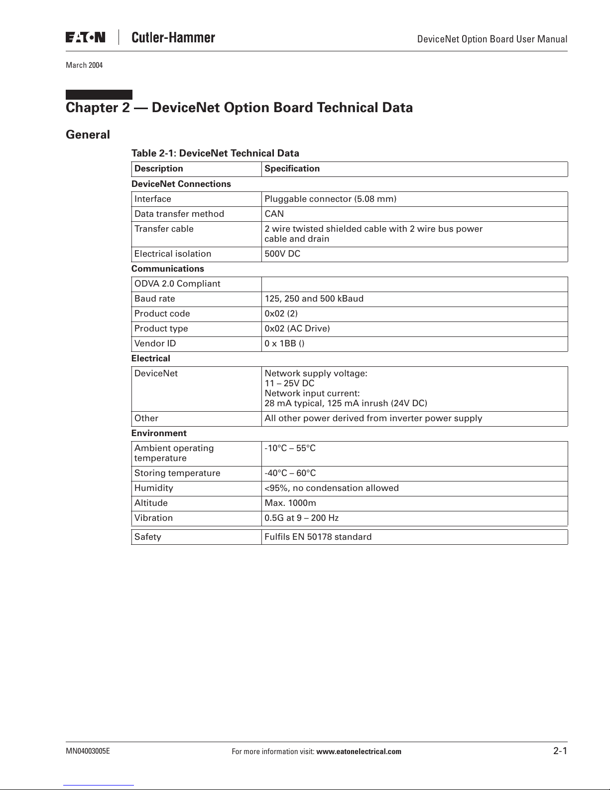
Chapter 2 — DeviceNet Option Board Technical Data
General
Table 2-1: DeviceNet Technical Data
Description Specification
DeviceNet Connections
Interface Pluggable connector (5.08 mm)
Data transfer method CAN
Transfer cable 2 wire twisted shielded cable with 2 wire bus power
Electrical isolation 500V DC
Communications
ODVA 2.0 Compliant
Baud rate 125, 250 and 500 kBaud
Product code 0x02 (2)
Product type 0x02 (AC Drive)
Vendor ID 0 x 1BB ()
Electrical
DeviceNet Network supply voltage:
Other All other power derived from inverter power supply
Environment
Ambient operating
temperature
Storing temperature -40°C – 60°C
Humidity <95%, no condensation allowed
Altitude Max. 1000m
Vibration 0.5G at 9 – 200 Hz
cable and drain
11 – 25V DC
Network input current:
28 mA typical, 125 mA inrush (24V DC)
-10°C – 55°C
DeviceNet Option Board User Manual
Safety Fulfils EN 50178 standard
MN04003005E
For more information visit:
www.eatonelectrical.com
2-1
DeviceNet Option Board User Manual
DeviceNet Features and Functionality
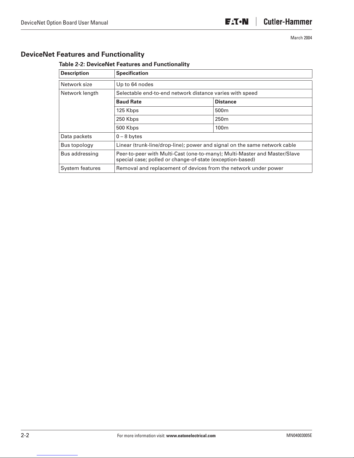
Table 2-2: DeviceNet Features and Functionality
Description Specification
Network size Up to 64 nodes
Network length Selectable end-to-end network distance varies with speed
Baud Rate Distance
125 Kbps 500m
250 Kbps 250m
500 Kbps 100m
Data packets 0 – 8 bytes
Bus topology Linear (trunk-line/drop-line); power and signal on the same network cable
Bus addressing Peer-to-peer with Multi-Cast (one-to-many); Multi-Master and Master/Slave
special case; polled or change-of-state (exception-based)
System features Removal and replacement of devices from the network under power
March 2004
2-2
For more information visit:
www.eatonelectrical.com
MN04003005E
March 2004
Chapter 3 — DeviceNet
Introduction
DeviceNet is an open network based on CAN that is designed to connect low cost industrial
control devices (such as limit switches, photoelectric sensors, motor starters, process
sensors, adjustable frequency drives, panel displays and operator interfaces) to a network
and eliminate expensive hardwiring.
The direct connectivity provides improved communication between devices as well as
important device-level diagnostics not easily accessible or available through hardwired
I/O interfaces.
The DeviceNet Model is application independent; it provides the communication services
needed by various types of applications.
Many of today’s lower level industrial control devices must retain their low cost/low resource
characteristics even when directly connected to a network. DeviceNet takes this into
consideration by defining a specific instance of the Model for communications typically
seen in a Master/Slave application. This is referred to as the Predefined Master/Slave
Connection Set.
DeviceNet Option Board User Manual
DeviceNet allows the interchangeability of simple devices while making interconnectivity for
more complex devices possible. In addition to reading the state of discrete devices,
DeviceNet provides the capability to report temperatures, to read the load current in a motor
starter, to change the deceleration rate of drives, or to count the number of packages that
have passed on a conveyor in the previous hour.
DeviceNet Physical Layer and Media
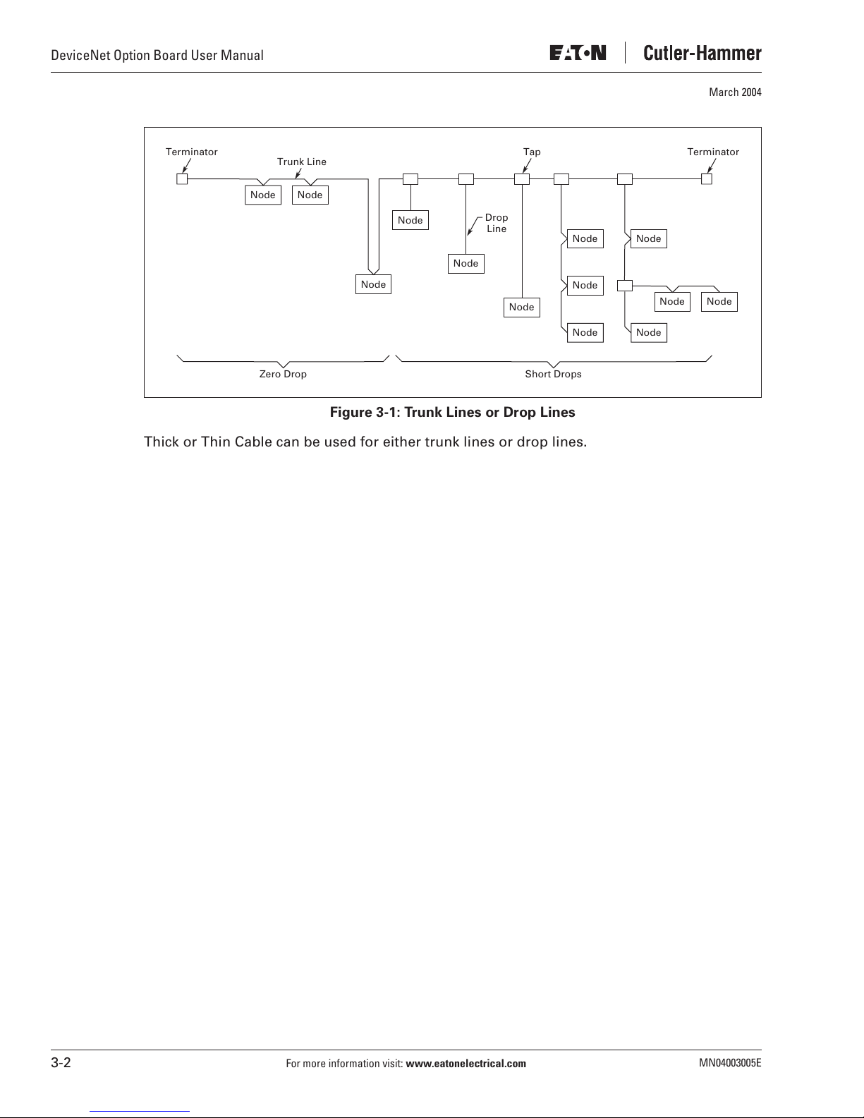
The basic trunk-line/drop-line topology provides separate twisted pair busses for both signal
and power distribution. Thick or thin cable can be used for either trunk lines or drop lines.
End-to-end network distance varies with data rate and cable size.
Devices can be powered directly from the bus and communicate with each other using the
same cable.
network
Power taps can be added at any point in the network which makes redundant power supplies
possible. The trunk-line current rating is 8 amps. An opto-isolated design option allows
externally powered devices (e.g. AC drives, starters and solenoid valves) to share the same
bus cable. Other CAN-based networks allow only a single power supply (if at all) for the
entire network.
Nodes can be removed or inserted from the network without powering down the
.
MN04003005E
For more information visit:
www.eatonelectrical.com
3-1
DeviceNet Option Board User Manual
March 2004
Terminator Tap Terminator
Trunk Line
Node Node
Node
Node
Node
Drop
Line
Node
Node
Node
Node
Short DropsZero Drop
Node
Node Node
Node
Figure 3-1: Trunk Lines or Drop Lines
Thick or Thin Cable can be used for either trunk lines or drop lines.
3-2
For more information visit:
www.eatonelectrical.com
MN04003005E
DeviceNet Option Board User Manual
March 2004
Chapter 4 — DeviceNet Option Board Layout and Connections
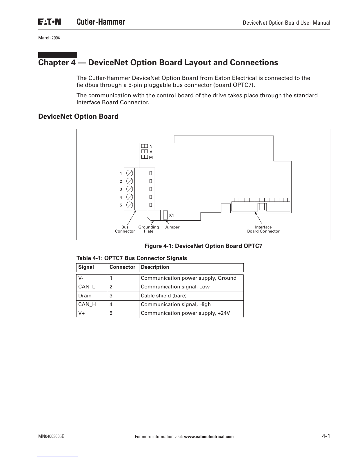
The Cutler-Hammer DeviceNet Option Board from Eaton Electrical is connected to the
fieldbus through a 5-pin pluggable bus connector (board OPTC7).
The communication with the control board of the drive takes place through the standard
Interface Board Connector.
DeviceNet Option Board
N
A
M
1
2
3
4
5
X1
Bus
Connector
Grounding
Plate
Jumper
Figure 4-1: DeviceNet Option Board OPTC7
Table 4-1: OPTC7 Bus Connector Signals
Signal Connector Description
V- 1 Communication power supply, Ground
CAN_L 2 Communication signal, Low
Drain 3 Cable shield (bare)
CAN_H 4 Communication signal, High
V+ 5 Communication power supply, +24V
Interface
Board Connector
MN04003005E
For more information visit:
www.eatonelectrical.com
4-1
DeviceNet Option Board User Manual
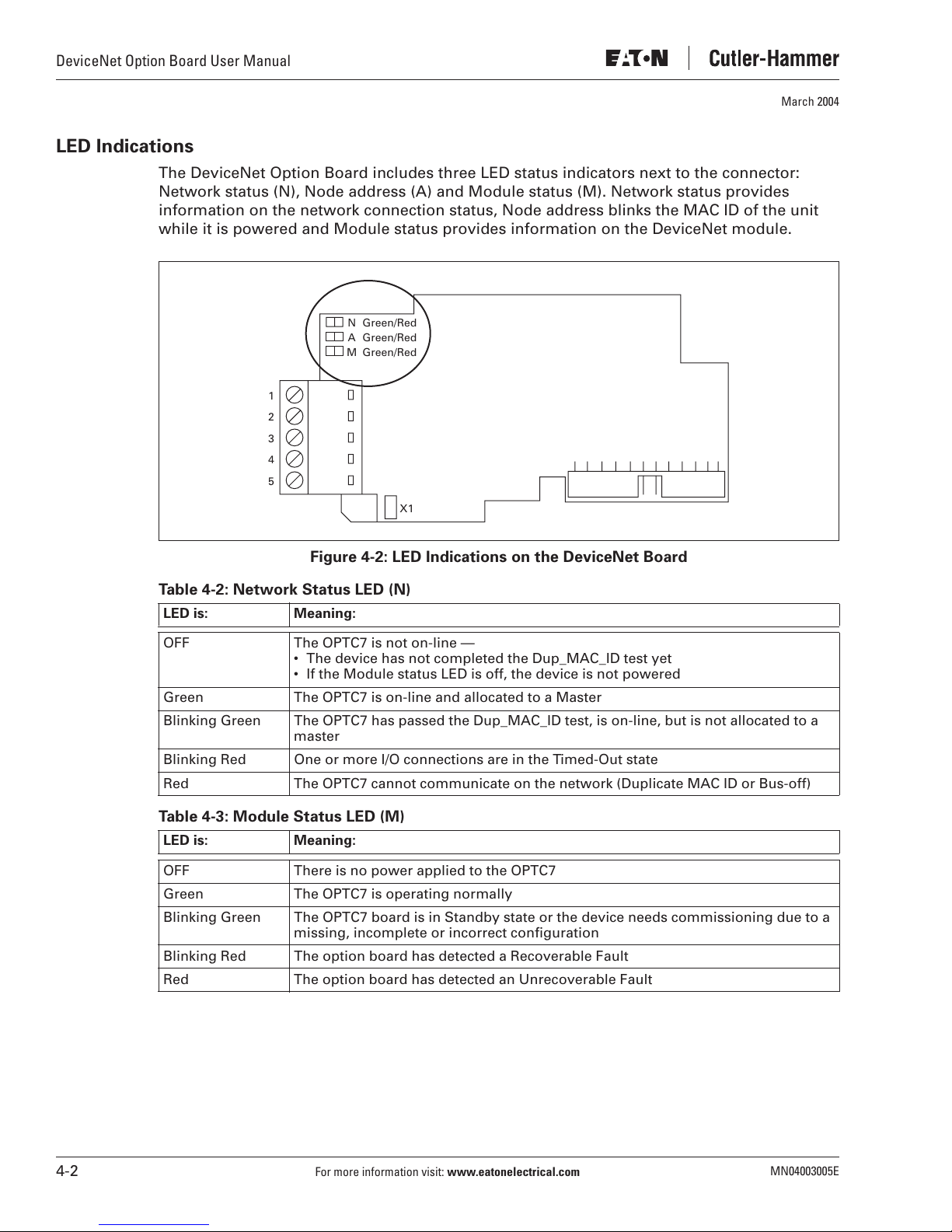
LED Indications
The DeviceNet Option Board includes three LED status indicators next to the connector:
Network status (N), Node address (A) and Module status (M). Network status provides
information on the network connection status, Node address blinks the MAC ID of the unit
while it is powered and Module status provides information on the DeviceNet module.
1
2
3
4
5
NGreen/Red
Green/Red
A
Green/Red
M
March 2004
X1
Figure 4-2: LED Indications on the DeviceNet Board
Table 4-2: Network Status LED (N)
LED is: Meaning:
OFF The OPTC7 is not on-line —
• The device has not completed the Dup_MAC_ID test yet
• If the Module status LED is off, the device is not powered
Green The OPTC7 is on-line and allocated to a Master
Blinking Green The OPTC7 has passed the Dup_MAC_ID test, is on-line, but is not allocated to a
master
Blinking Red One or more I/O connections are in the Timed-Out state
Red The OPTC7 cannot communicate on the network (Duplicate MAC ID or Bus-off)
Table 4-3: Module Status LED (M)
LED is: Meaning:
OFF There is no power applied to the OPTC7
Green The OPTC7 is operating normally
Blinking Green The OPTC7 board is in Standby state or the device needs commissioning due to a
missing, incomplete or incorrect configuration
Blinking Red The option board has detected a Recoverable Fault
Red The option board has detected an Unrecoverable Fault
4-2
For more information visit:
www.eatonelectrical.com
MN04003005E

March 2004
Node Address LED (A)
This LED blinks the MAC ID of the unit while it is powered. The tens are displayed with red
blinks and the ones with green blinks. The unit plays the tens, then the ones and finally
delays about 2 seconds before repeating the sequence.
LED Test
An LED test is performed at power-up. The following sequence is performed:
1. All LEDs OFF
2. All LEDs Green (0.25 s)
3. All LEDs Red (0.25 s)
4. All LEDs OFF
5. Start of Normal Operation
Connection of DeviceNet Drop-Line Cable
The following instructions lead you through the connection of the OPTC7 to the DeviceNet
system and show you the power-up and grounding of the board.
DeviceNet Option Board User Manual
Table 4-4: Connection and Power-Up
Step Procedure
A
Lead the DeviceNet drop-line cable through
the right gridded hole on the bottom of the
drive. Make a sufficiently wide opening for
the cable by cutting the grid as wide as
necessary (see Step E on
Page 5-2
)
MN04003005E
For more information visit:
www.eatonelectrical.com
4-3
DeviceNet Option Board User Manual
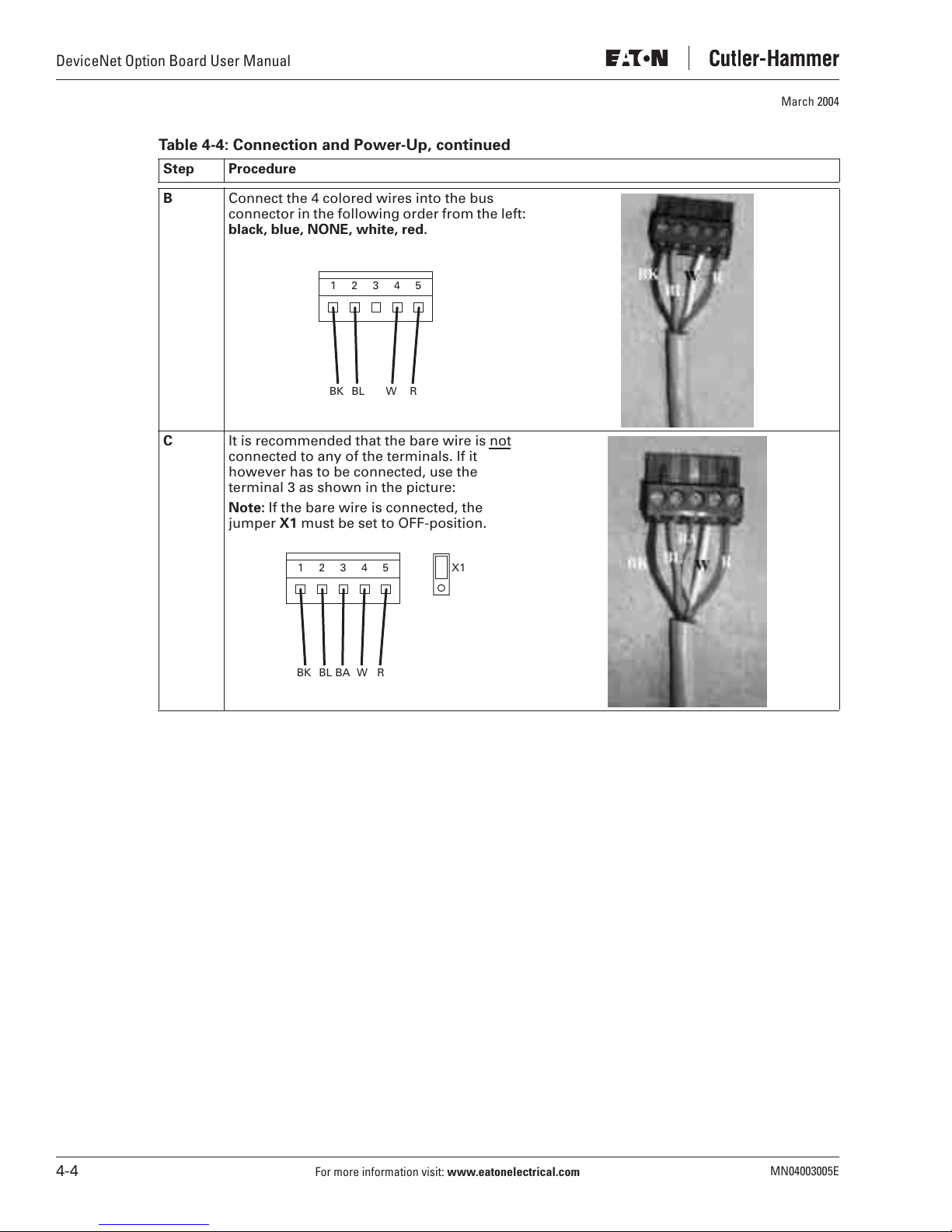
Table 4-4: Connection and Power-Up, continued
Step Procedure
March 2004
B
Connect the 4 colored wires into the bus
connector in the following order from the left:
black, blue, NONE, white, red.
12345
BK BL W
C
It is recommended that the bare wire is not
R
connected to any of the terminals. If it
however has to be connected, use the
terminal 3 as shown in the picture:
Note:
If the bare wire is connected, the
jumper X1 must be set to OFF-position.
12345
X1
BK BL WBA
R
4-4
For more information visit:
www.eatonelectrical.com
MN04003005E
March 2004
Chapter 5 — Installation of DeviceNet Option Board
Note:
These instructions apply only to field installations. Otherwise, the board has already
been installed for you at the factory.
CAUTION
Make sure that the drive
fieldbus board is changed or added.
Before taking any commissioning actions, carefully read the safety
instructions in the
9000X User’s Manual
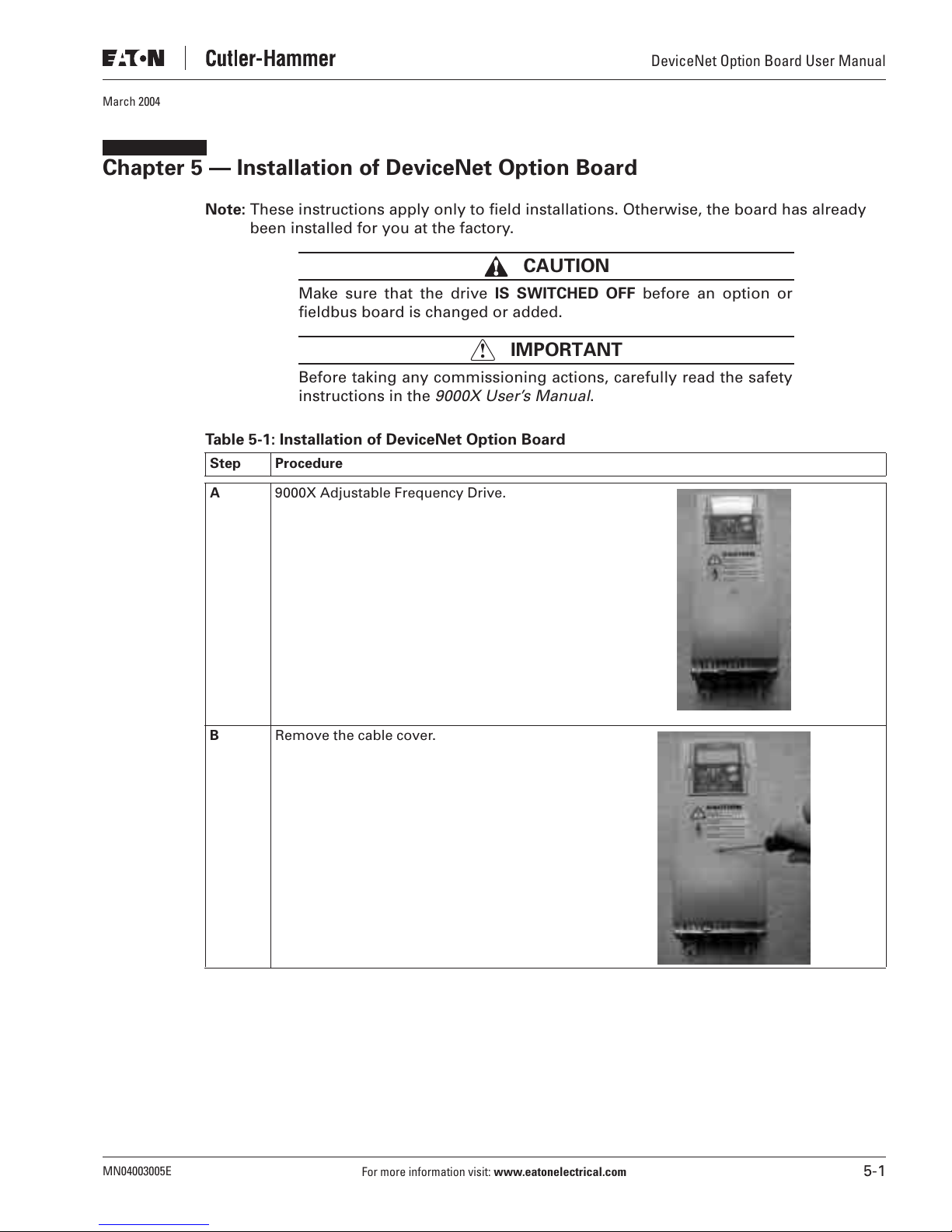
Table 5-1: Installation of DeviceNet Option Board
Step Procedure
IS SWITCHED OFF
IMPORTANT
!
.
DeviceNet Option Board User Manual
before an option or
A
B
9000X Adjustable Frequency Drive.
Remove the cable cover.
MN04003005E
For more information visit:
www.eatonelectrical.com
5-1
DeviceNet Option Board User Manual
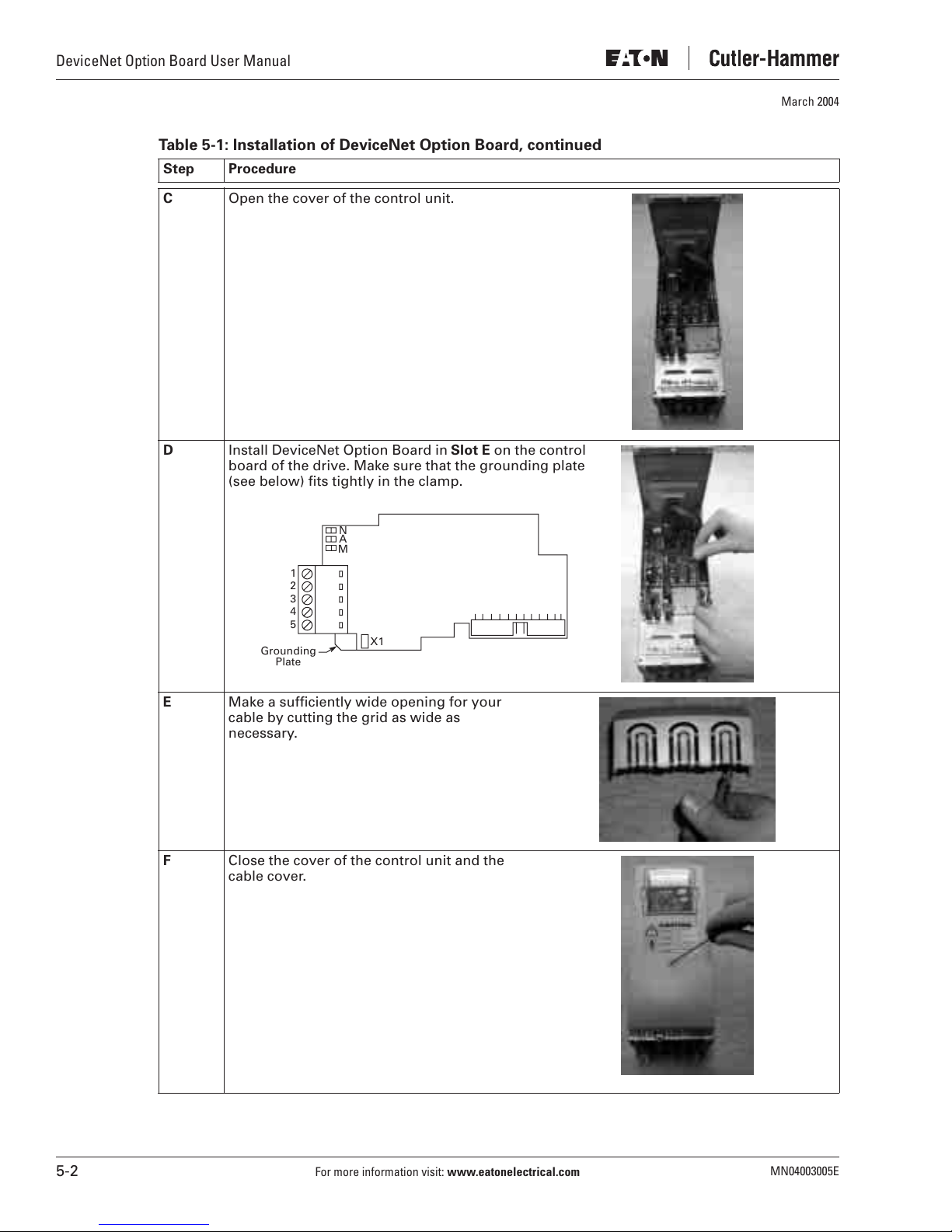
Table 5-1: Installation of DeviceNet Option Board, continued
Step Procedure
C Open the cover of the control unit.
D Install DeviceNet Option Board in Slot E on the control
board of the drive. Make sure that the grounding plate
(see below) fits tightly in the clamp.
March 2004
N
A
M
1
2
3
4
5
Grounding
Plate
X1
E Make a sufficiently wide opening for your
cable by cutting the grid as wide as
necessary.
F Close the cover of the control unit and the
cable cover.
5-2
For more information visit:
www.eatonelectrical.com
MN04003005E
 Loading...